Running 1/16 flux core wire at the wrong settings is the fastest way to burn a day’s worth of plate, clog your contact tip, and still walk away with a bead you would not show anyone. The short version: for self-shielded 1/16″ (1.6 mm) wire, start around 150–250 ipm at 20–24 volts with a 1 inch stick-out on DCEN polarity; for gas-shielded 1/16″ wire, start around 140–280 ipm at 23–27 volts on DCEP with 75/25 argon-CO2. Everything below explains why those numbers move, and how to find the exact window for your machine, your position, and your plate.
Dave had been stick welding for twenty years before he bought his first wire feeder. The project was simple enough: a pair of 1/2-inch plate brackets for a hay barn frame, eight fillet welds, nothing exotic. He loaded a spool of 0.035-inch flux core wire, set the machine where the door chart suggested, and struck an arc. The wire stubbed, popped, and burned back into the contact tip. He turned the wire speed up. Now the arc sounded like frying bacon and spatter peppered his sleeves. He turned the voltage up. The bead went flat and wide, washed at the toes, and still did not tie into the corner.
What Dave was really fighting was a diameter problem wearing a settings disguise. He was trying to push enough metal through a straw. The job needed 1/16-inch wire — 1.6 millimeters of tubular steel with flux packed down its core — feeding at the higher currents that wire is designed for. Within twenty minutes of switching spools and dialing in a real starting point, his beads were stacked, quiet, and tied in at both toes.
That is the whole game with 1/16 flux core wire settings: get the diameter right, get the polarity right, then tune three variables — wire feed speed, voltage, and stick-out — in the right order. This guide walks through every one of them, with published starting numbers from manufacturer operating charts, position-by-position adjustments, a troubleshooting table for the defects you are actually seeing, and answers to the questions welders ask once they spool up the heavy wire for the first time.
What 1/16 Flux Core Wire Actually Is
1/16 flux core wire measures 0.0625 inches, or 1.6 millimeters, in diameter. Like every flux-cored electrode, it is not a solid rod. It is a low-carbon steel sheath rolled into a tube and filled with a powdered flux of iron ores, deoxidizers, arc stabilizers, and gas formers. When the arc melts the wire, that core does three jobs at once: it creates a shielding gas around the puddle (or supplements the external gas, depending on the wire), it leaves a slag layer that protects the cooling bead, and it adds alloying elements that determine the weld metal’s strength and toughness.
The 1/16 size sits at the heavy end of what manual wire feeders commonly handle. Most hardware-store flux core spools are 0.030 or 0.035 inches. Industrial shops step up to 0.045, and 1/16 is where heavy fabrication, structural work, and high-deposition applications live. The practical differences show up in three places:
- More current, more penetration. Bigger wire carries more amperage before it melts off. Published operating data from Lincoln Electric shows 1/16 self-shielded wire running from roughly 170 amps at 150 ipm up to about 300 amps at 350 ipm. A 0.035 spool rarely sees 160 amps in manual work.
- Higher deposition rates. The same Lincoln operating chart lists melt-off rates climbing from about 5.4 lb/hr to 12 lb/hr as wire feed speed moves from 150 to 350 ipm. Stick electrodes like a 7018 deposit around 2 to 4 lb/hr in the hands of most welders. That gap is why structural shops moved from stick to flux core for out-of-position and heavy fillet work.
- A wider, more forgiving bead on thick plate. At matched travel speeds, the larger wire lays a fuller bead with fewer passes on 3/8-inch-and-up material — but it also stores more heat, which makes it the wrong tool for sheet metal. That trade-off is the first thing to accept: 1/16 wire is a plate wire.
One clarification that saves confusion at the supply counter: “flux core wire” covers two different processes with different chemistry and different polarity requirements. Self-shielded flux core (FCAW-S, sometimes called “gasless” flux core) carries everything it needs inside the wire. Gas-shielded or “dual shield” flux core (FCAW-G) uses a flux core plus an external cylinder of CO2 or argon/CO2. The same 1/16 diameter is sold for both, but they are not interchangeable in setup — polarity, stick-out, and voltage windows all differ. You cannot tell them apart by looking at a bare spool; you read the classification stamped on the label, and that classification tells you everything.
Before You Touch a Dial: Three Setup Checks That Matter More Than Settings
Experienced welders know that most “bad settings” are actually bad setups wearing a disguise. Spend five minutes on these three checks and half your troubleshooting disappears before you strike an arc.
1. Polarity: the single most common mistake
Flux core wire is picky about which way the current runs, and getting it backwards produces a weld that looks almost passable but performs poorly — heavy spatter, shallow penetration, and a slag that fights you. The rule is written into the wire classification:
| Wire type |
Classification examples |
Correct polarity |
Shielding |
| Self-shielded (FCAW-S) |
E71T-8, E71T-11, E71T-GS |
DCEN (electrode negative, “straight”) |
Flux only — no gas |
| Gas-shielded (FCAW-G) |
E71T-1C, E71T-1M, E70T-1 |
DCEP (electrode positive, “reverse”) |
100% CO2 or 75% Ar / 25% CO2 |
| Solid MIG wire (for contrast) |
ER70S-6 |
DCEP |
Gas required |
Notice the trap: self-shielded flux core runs on DCEN, the opposite of solid MIG wire and gas-shielded flux core. If you ran MIG yesterday and spool up flux core today without swapping your gun polarity leads, you will chase settings all afternoon. As Hobart Brothers puts it in its technical guidance on self-shielded wire, “using the incorrect polarity can result in poor welding performance, including increased spatter levels.”
There is real science behind why self-shielded wire wants DCEN. Educational material from Portland Community College’s welding program explains that E71T-8 and E71T-11 electrodes need the wire itself heated before it reaches the arc, so the flux ingredients can decompose and release their shielding gas high above the puddle. DCEN pushes more heat into the electrode, and the long stick-out these wires require adds resistance heating on top of it — a toasting effect that preps the flux. Run them on DCEP and you starve that reaction: less gas, more atmospheric contamination, weaker mechanical properties.
2. Can your machine actually push 1/16 wire?
1/16 flux core wire wants real power. The published operating windows for this diameter run from about 170 to 300+ amps, which means a 140-amp hobby MIG machine is out of its depth — not because it cannot melt the wire, but because it cannot deliver the current with any duty cycle left. Before committing to the diameter, check three things:
- Output rating. Look for a welder rated at least 200 amps at 30% duty cycle, preferably 250–300 amps. Machines in the 180–250 A multiprocess class are the natural home for 1/16 wire.
- Drive roll capacity. Your rolls must be knurled or V-groove sized for 1/16 (some ships ship 0.030/0.035 V-rolls only). Tubular wire is soft — knurled rolls grip it without crushing the sheath. Roll pressure should be “just enough” that the wire cannot slip; overtightening deforms the tube and causes feeding problems downstream.
- Liner and contact tip size. A .035 liner running 1/16 wire creates friction and erratic feed. Swap to the correct liner diameter, and use the matching contact tip — usually 1/16 with a 0.052 or 1/16 bore. A mismatched tip is a silent cause of arc instability that looks like a settings problem.
3. Read the classification, not the marketing label
The spool label is your specification sheet. The AWS classification (E71T-8, E71T-11, E71T-1C, and so on) tells you shielding type, tensile strength, position capability, and toughness requirements. Quick decoder:
- E71T-11 — self-shielded, all-position, general purpose, DCEN. The common “gasless” wire. Wide parameter tolerance, moderate penetration, good for farm and repair work.
- E71T-8 — self-shielded, all-position, DCEN, designed for higher toughness and low-temperature impact requirements; frequently accepted for structural work under codes like AWS D1.1 when the procedure qualifies. Longer stick-out than T-11, and notably, its smallest available diameter is typically 1/16 — this is where the big self-shielded wire lives.
- E71T-1C / E71T-1M — gas-shielded (dual shield) with CO2 or argon/CO2 respectively, DCEP, all-position, deep penetration, low spatter. The production workhorse for structural steel.
- E70T-1 — similar to 71T-1 but 70 ksi tensile class, common on heavier plate and multipass work.
A warning worth repeating because it causes real damage: never run a self-shielded wire (T-8, T-11, T-GS) with an external shielding gas. The Portland Community College material is blunt about it — those wires contain roughly 15% aluminum as a deoxidizer and denitrifier, sized to react with the nitrogen and oxygen in open air. Add argon and that aluminum instead forms brittle intermetallic compounds in the weld metal, wrecking its mechanical properties. Gas on a gasless wire does not improve it; it contaminates it.
The Three Variables That Define Every 1/16 Flux Core Setting
Every settings chart you will ever read — the one inside your machine door, the wire data sheet, the tables later in this article — is describing the same three knobs plus one habit. Understanding what each one actually controls prevents the circular tuning spiral where you turn two things at once and never learn anything.
Wire feed speed: your amperage dial
On a constant-voltage wire feeder, you do not set amperage directly. You set how fast wire arrives, and the arc physics decide the current. More feed speed means more wire must melt per second, which pulls more amps. This is why every FCAW chart is really an amperage chart in disguise: wire feed speed is the input, current is the outcome, and the two move together with a ratio of roughly 0.85 to 1.15 amps per ipm for 1/16 wire depending on stick-out and voltage.
Practical consequence: wire feed speed is how you match the weld to material thickness. Thicker plate needs more current, so feed speed climbs with thickness. If your weld looks cold — sitting on top of the plate, convex, with sharp edges and no tie-in — the wire speed is too low for the job (or the voltage is too high, which we get to next).
Voltage: your arc length and bead shape dial
Voltage controls how long the arc burns and how wide the bead spreads. Too little voltage and the arc is short, harsh, and stubbing — the wire hits the plate faster than it can melt, and you hear popping. Too much voltage and the arc lengthens, the bead flattens and widens, spatter increases, and on self-shielded wire you begin to burn off the alloying elements that were supposed to protect the puddle.
The tuning sequence matters. Set feed speed for the thickness first, then adjust voltage until the bead profile is right: a smooth, slightly convex bead about 1.5 to 2 times the wire diameter wide, with clean edges that wet into the toes. The classic adjustment step for flux core is half a volt at a time — flux core has a narrower voltage sweet spot than solid MIG wire, and 0.5 V is a visible difference.
Stick-out: the variable most welders ignore
Stick-out — properly called contact-tip-to-work distance, or CTWD — is the length of wire between the contact tip and the plate. It matters far more in flux core than in MIG because that protruding wire carries current and heats up resistively before it ever reaches the arc. Longer stick-out means more resistance, more preheating, more flux activation, and lower welding current.
Published data from an industry FCAW procedure guide illustrates the sensitivity. Holding every other setting constant:
| Electrode extension (ESO) |
8 mm (5/16″) |
12 mm (1/2″) |
16 mm (5/8″) |
20 mm (3/4″) |
24 mm (1″) |
| Resulting current |
202 A |
187 A |
172 A |
162 A |
154 A |
| Arc voltage |
27.0 V |
27.8 V |
28.1 V |
28.4 V |
28.6 V |
That is nearly 50 amps of swing from a quarter-inch-plus change in gun distance, with voltage drifting up as a side effect. Industry guidance from Welders Supply rounds it to a practical rule of thumb: 20 to 25 amps per quarter inch of stick-out change on a typical setup. Either way, the conclusion is the same — consistent gun distance is a settings variable, and a welder who moves in and out while traveling is changing their amperage mid-bead without touching a dial.
For 1/16 wire, the recommended windows are longer than you might expect: about 3/4 to 1-1/4 inches for self-shielded wire (1 inch to 1-1/4 inches for E71T-8 specifically), and about 3/4 to 1 inch for gas-shielded wire. Miller Electric’s flux core guidance puts the general figure at roughly 3/4 inch — about twice what solid MIG wire wants — and stresses holding it steady.
1/16 Flux Core Wire Settings Chart: Self-Shielded (FCAW-S)
These starting points are built from published manufacturer operating procedures for 1/16 (1.6 mm) self-shielded wire, plus general ranges reported for E71T-8 and E71T-11 classifications. Remember they assume DCEN polarity, no shielding gas, flat position, and the stick-out listed in the final column. Treat them as a proven first dial-in, then tune on scrap of the same thickness you are about to weld.
| Material thickness |
Wire feed speed (ipm) |
Voltage (V) |
Approx. amps (A) |
Stick-out |
| 3/16″ (4.8 mm) |
130–170 |
18–20 |
130–170 |
3/4″–1″ |
| 1/4″ (6.4 mm) |
150–200 |
19–21 |
150–200 |
3/4″–1″ |
| 3/8″ (9.5 mm) |
190–250 |
20–22 |
180–240 |
1″–1-1/4″ |
| 1/2″ (12.7 mm) |
230–300 |
21–23 |
210–280 |
1″–1-1/4″ |
| 5/8″ and heavier (multi-pass) |
260–330 |
22–24 |
240–310 |
1″–1-1/4″ |
For reference against a fully published chart: Lincoln Electric’s operating data for Lincore self-shielded wire lists 1/16 inch on DC+ at a 1-1/4 inch electrode extension running 150 ipm at 22 V and 170 A, climbing to 250 ipm at 24 V and 250 A, and topping out at 350 ipm at 26 V and 300 A. Hobart Brothers describes the E71T-8 window more broadly as 18–23 volts and 200–275 amps for all-position work across its available diameters, with E71T-11 covering 17–22 volts and 50–275 amps depending on diameter. Your machine’s door chart remains the final authority for your specific model — but if your numbers fall far outside these ranges, something in the setup is off.
1/16 Flux Core Wire Settings Chart: Gas-Shielded / Dual Shield (FCAW-G)
Gas-shielded 1/16 wire flips the polarity to DCEP, adds a gas cylinder (75% argon / 25% CO2 is the smooth-running default; 100% CO2 buys deeper penetration at the cost of more spatter and roughly 1–2 extra volts), and trades some of the weather tolerance of self-shielded wire for a calmer arc and better penetration. Gas flow for this process typically runs 35–45 CFH — enough to cover the puddle without creating turbulence that actually pulls air in. Outdoors or in a draft, crank flow slightly or screen the area; industry guidance notes that once wind exceeds about 5 miles per hour, gas shielding starts breaking down, and above 8 mph you should switch to self-shielded wire entirely.
| Material thickness |
Wire feed speed (ipm) |
Voltage (V) |
Approx. amps (A) |
Gas flow |
| 1/4″ (6.4 mm) |
140–180 |
23–25 |
165–200 |
35–40 CFH |
| 3/8″ (9.5 mm) |
170–220 |
24–26 |
195–240 |
35–40 CFH |
| 1/2″ (12.7 mm) |
200–250 |
25–27 |
220–270 |
40–45 CFH |
| 3/4″ (19 mm) |
230–280 |
26–28 |
250–300 |
40–45 CFH |
| 1″ (25.4 mm) |
250–320 |
27–29 |
270–330 |
45 CFH |
Lincoln Electric’s published operating procedures for 1/16 inch gas-shielded wire on 75/25 at a 1-inch contact-tip-to-work distance give a concrete anchor: 140 ipm at 24–26 V produces about 170 amps; 195 ipm at 24–26 V about 200 amps; 280 ipm at 25–27 V about 220 amps — and the data sheet notes to add 2 volts when running 100% CO2. If you are welding heavier sections where the amp range starts to exceed your machine’s output, that is your sign that multipass welding — not more dial — is the answer.
Practical note on gas choice: 100% CO2 penetrates deeper and costs less per cylinder, but it runs hotter and rougher on thin edges. 75/25 argon/CO2 gives a quieter arc, less spatter, and a nicer bead profile for out-of-position work. If you dial in settings on one gas, expect to shift a volt or two when you switch — a chart tuned for 75/25 will feel cold on CO2.
Adjusting 1/16 Settings for Welding Position
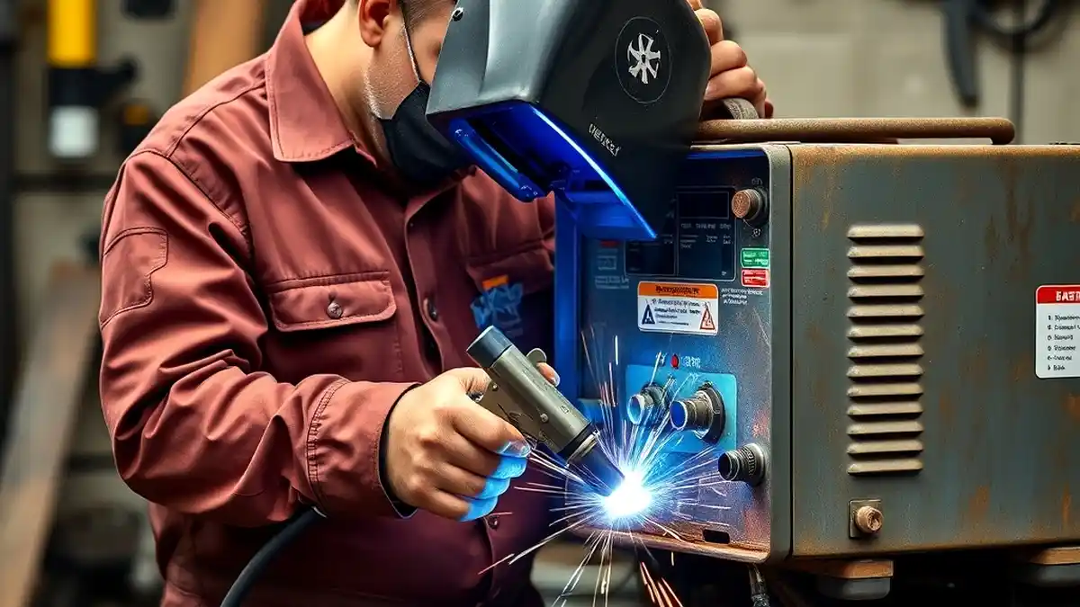
The charts above assume flat, downhand welding — the easiest position and the one where gravity works for you. The moment you move out of position, the puddle wants to sag, so you have to stiffen it by cooling the arc. Every reputable source agrees on the magnitude of the correction; only the decimals move slightly.
| Position |
Wire feed speed adjustment |
Voltage adjustment |
Technique notes |
| Flat (1F/1G) |
Chart baseline |
Chart baseline |
Drag technique, 5–15° travel angle |
| Horizontal (2F/2G) |
Reduce 5–10% |
Stay at lower end of range |
Work angle tilted 0–15° upward; slight downward gun angle fights sag |
| Vertical up (3F/3G) |
Reduce 10–15% |
Drop 1–2 V |
Short arc, tight weave or straight stringer, pause at toes |
| Vertical down (thin material) |
Reduce 10–15% |
Drop 1–2 V |
Wire kept on leading edge of puddle; fast travel; root passes on light plate |
| Overhead (4F/4G) |
Reduce 15–20% |
Drop 1–2 V |
Tightest stick-out, minimum weave, steady fast travel; smallest practical wire |
Miller Electric’s guidance for out-of-position flux core work puts overhead in the starkest terms: lower your parameters by 15 to 20 percent, minimize weaving, and move fast — and even then, overhead remains the hardest weld in the book. The vertical-up reduction of 10 to 15 percent appears across manufacturer charts because the puddle in an uphill fillet sits on itself; excess heat makes it sag out of the joint before it can solidify.
A subtle point that separates competent out-of-position work from great work: when you reduce settings for position, reduce wire feed speed first and voltage second. Dropping voltage too far on a vertical fillet shortens the arc until the wire stubs into the joint, which creates the exact porosity you were trying to avoid. Keep a functional arc length and take the heat out with feed rate and travel speed.
Stick-Out Deep Dive: The Hidden Settings Knob
We covered why stick-out moves amperage; here is how to use it deliberately. Three practical rules cover most situations:
- Match the stick-out to the wire type. Self-shielded E71T-8 wants the longest — 1 inch to 1-1/4 inches — because that resistance heat is what activates its flux. E71T-11 and general self-shielded wire run 3/4 inch to 1 inch. Gas-shielded wire wants shorter, around 3/4 inch to 1 inch, since its gas shield does not depend on flux activation happening far above the puddle.
- Do not go shorter than about 1/2 inch with 1/16 wire. Cramped stick-out means the arc sits near the contact tip, the tip overheats, spatter builds inside the nozzle, and you get tip-to-work shorts. Industry guidance flags extensions below 12 mm (about 1/2 inch) as a contact tip damage risk, and above 30 mm (1-1/4 inches) as a lack-of-penetration risk — the arc never reaches the root because too much of the current is spent heating wire instead of base metal.
- Hold it constant. The most common operator error in flux core is a drifting gun distance. If your bead profile changes halfway through a pass, your stick-out changed, not your settings. Some welders tape a mark on the nozzle as a visual gauge until the distance becomes muscle memory.
There is a legitimate reason to lengthen stick-out on self-shielded wire beyond habit: shielding. The gas-forming ingredients in FCAW-S wires are designed to release protection high above the puddle so droplets pass through a protective envelope before landing. Shorten that distance and you are effectively welding with an incomplete shield — the result is porosity, often internal, that only shows up when you cut or bend the weld.
Technique: Travel Speed, Gun Angle, and the Drag Rule
Settings get you an arc; technique gets you a weld. Four habits matter most with 1/16 wire.
Drag, do not push
Flux core generates slag, and slag must be shielded from the atmosphere while the puddle is molten. That means the gun points back at the finished weld and pulls away from it — the classic mnemonic is “if there’s slag, you drag.” Pushing directs the arc and gas ahead of the puddle and leaves the molten metal exposed behind it, which invites porosity and trapped slag. Industry procedure guidance recommends a backhand technique with the gun 60–70° from horizontal for downhand work; the practical translation for most welders is a 5 to 15 degree drag angle from vertical, which is also the range Miller recommends for general flux core travel angle. Angles beyond 20–25 degrees start to cost penetration and add spatter.
Travel speed: the fill-versus-fusion balance
Because flux core deposits metal roughly twice as fast as stick welding at the same current, travel speed has to rise proportionately to keep the puddle controllable. Move too slowly and you get excessive buildup, a convex rope of a bead, poor profile, and — on a fillet — lack of corner fusion as the arc outruns the deposition. Move too fast and the bead narrows, cold-lobs onto the plate, and leaves undercut at the toes. The target is a bead that ties into both toes with edges that feather out rather than stand up, laid at whatever speed your specific combination of feed speed and voltage demands. There is no universal inches-per-minute number worth quoting; there is a profile you are looking for. On a 3/8-inch fillet with 1/16 dual-shield wire, expect to travel somewhere in the 8 to 15 ipm range — fast enough that the puddle stays behind the arc, slow enough that both toes wet in.
Weave width and dwell
With a wire this size, a stringer bead covers a lot of joint. For fillets up to about 1/4-inch leg, straight stringers beat weaving every time — less heat, less risk of trapped slag, better grain structure. When a wider joint or a cover pass does call for a weave, keep the width to about 2.5 times the wire diameter and dwell at the toes long enough to let the puddle wash in. Pause too briefly at the sides and you leave undercut; dwell too long and the center builds high. On vertical-up, the weave is a small side-to-side manipulation with the arc held mostly at the leading edge; heavy zigzag patterns on an uphill fillet are how welders get sagging, lumpy beads no matter what the machine says.
Cleanliness and starts
Flux core is more forgiving of mill scale than MIG, but it is not indifferent to oil, paint, heavy rust, and moisture. Wire-brush the joint, wipe off cutting fluids, and dry wet plate. Trim the wire tip before every start — a wire with a flux bead welded to its end will pop and sputter on arc strike instead of establishing cleanly. And keep slag fully removed between multipass runs; a wire brush and chipping hammer between passes takes thirty seconds and prevents the single most common structural defect in multipass flux core work: slag inclusions that show up as a failure during inspection long after the job looked finished.
A Step-by-Step Dial-In Procedure for Your First Spool
Theory is fine, but the first time you load 1/16 wire you want a checklist you can follow in order. This is the sequence that works, and it deliberately front-loads the free checks before you waste any plate.
- Confirm the wire and the classification. Read the spool label: diameter, E-classification, and required polarity. If it says gas-shielded, get the cylinder out; if it says self-shielded, make sure no gas is connected.
- Set polarity at the machine. Swap the internal gun and work-lead connections to match step 1. If your machine has a polarity switch or quick-connects, this takes thirty seconds. Skip it and every later step is meaningless.
- Install matched hardware. Correct-size liner, 1/16 contact tip, drive rolls sized for 1/16 (knurled preferred for tubular wire), roll pressure set so the wire cannot slip but the sheath does not deform. Feed a couple of feet of wire through with the gas off and check that it exits smoothly with no start-stop hesitation.
- Set stick-out before voltage. Clip the wire so exactly 1 inch (self-shielded) or 3/4 inch (gas-shielded) extends from the tip, then strike up holding that distance. This is your reference position for everything that follows.
- Dial wire feed speed for your thickness. Start at the middle of the range for your plate from the charts above — or your machine’s door chart if it lists 1/16 wire for that thickness.
- Set voltage to build the right profile. Run a 3-inch bead. If it stubs and pops, raise voltage 0.5 V. If it is flat, wide, and washed out, drop 0.5 V. Iterate until the bead is slightly convex, appropriately wide, and quiet.
- Check the back side. On scrap of matched thickness, look for consistent penetration. A cold center line means more feed speed; excessive reinforcement with no back-side penetration means the joint needs beveling, not just more heat.
- Verify position adjustments. If you are about to weld out of position, apply the percentage reductions from the position table now, not in the middle of the joint.
- Write it down. Wire brand and classification, diameter, polarity, feed speed, voltage, stick-out, gas and flow, thickness, position. Your own verified numbers become the most useful chart you own — one that is calibrated to your machine instead of a generic one.
The whole procedure takes about fifteen minutes the first time. The second time, because you wrote everything down, it takes five. Most welders who abandon 1/16 wire in frustration do so because they skipped steps two and three — polarity and feed hardware — and spent the afternoon compensating for a setup problem with dial adjustments.
Heat Input: Doing the Math When the Joint Demands It
For general fabrication, bead appearance and penetration tell you enough. For work governed by a procedure — structural members, pressure-adjacent components, anything an inspector will examine — heat input becomes a number you have to stay under, and 1/16 wire makes it easy to exceed limits without noticing because it deposits so fast.
The standard formula, used across welding engineering references:
Heat Input (kJ/in) = (60 × Amps × Volts × Efficiency) ÷ (1000 × Travel Speed in ipm)
Efficiency for flux core arc welding is conventionally taken as about 0.8, reflecting how much arc energy actually reaches the work. Worked example: a vertical fillet at 220 amps, 25 volts, traveling 10 ipm.
(60 × 220 × 25 × 0.8) ÷ (1000 × 10) = 26.4 kJ/in, roughly 1.04 kJ/mm.
Why does that matter? Many structural procedures cap heat input around 50 kJ/in for carbon steel to control grain growth in the heat-affected zone, while some fine-grain or quenched-and-templated steels run much tighter limits — and preheat and interpass temperature requirements usually ride alongside those caps. The practical translation for a welder with a 1/16 spool: if you are covering ground quickly, you are also delivering energy quickly, so slow down only as much as you must, keep passes reasonable, and let the plate cool between passes rather than stacking heat. When a specification governs the joint, the numbers come from the qualified welding procedure specification — your job is to hold amps, volts, and travel speed inside what it states, and the formula above is how you prove you did.
Multipass Welding with 1/16 Wire
One advantage of stepping up to 1/16 wire is that it shrinks pass counts on thick material — but “fewer passes” does not mean “one pass on everything.” Plate beyond roughly 1/2 inch with a beveled joint, most structural groove welds, and anything requiring full penetration will still be built up in multiple layers. Each layer wants slightly different settings.
| Pass |
Settings position |
Why |
| Root pass |
Low end of chart range; reduce feed speed 5–10% |
Cooler puddle resists burn-through and gives the first bead control in an open joint |
| Fill passes |
Chart midpoint or slightly above |
Heat builds in a preheated joint; full settings are safe and deposition rate matters most here |
| Cap pass |
Upper end of voltage range, feed speed unchanged |
Extra half-volt to a volt flattens and widens the bead for a smoother finished profile |
Watch your interpass temperature. For most carbon steel work, industry practice keeps the temperature between passes below about 500°F (260°C) — cool enough to avoid degrading the heat-affected zone’s properties, warm enough that you are not laying hot metal onto cold plate. If the plate is too hot to touch comfortably with a gloved hand near the weld, take a break. On low-alloy and higher-strength steels, the interpass ceiling and preheat requirements come from the applicable welding procedure — AWS D1.1, the filler metal data sheet, or the engineer’s specification — not from habit.
Reading the Bead: Troubleshooting 1/16 Flux Core Welds
The arc tells you what is wrong if you know what to listen for. This table matches the symptoms you actually see on the plate with the settings behind them. Work down the list in order — check polarity before anything else, because wrong polarity mimics about five different settings problems at once.
| Symptom |
Most likely cause |
Fix |
| Wire stubs into the plate, popping arc |
Feed speed too high for voltage, or voltage too low |
Raise voltage 0.5 V at a time, or drop feed speed 10–20 ipm |
| Wire burns back into the contact tip |
Voltage too high, feed too slow, or stick-out too short |
Increase feed speed; reduce voltage; lengthen stick-out to spec |
| Heavy spatter everywhere |
Wrong polarity (check first), voltage/feed mismatch, contaminated wire or plate |
Confirm DCEN or DCEP per label; re-center voltage; clean joint |
| Bead sits on top, convex, sharp edges |
Cold joint: not enough heat |
Increase feed speed 15–25 ipm, then trim voltage to restore profile |
| Bead flat, wide, thin, washed-out toes |
Too hot or travel too slow |
Lower voltage 0.5–1 V, speed up travel |
| Undercut at the toes |
Travel too fast, voltage too high, or weave dwell too short |
Slow slightly, dwell at toes, or drop voltage half a volt |
| Porosity inside the bead |
Stick-out too long (FCAW-S), wind on gas-shielded wire, dirty plate, or trapped slag |
Shorten stick-out, screen the gas, clean the joint, remove all slag |
| Worm tracks / gas marks |
Excessive voltage, long arc, moisture in flux, contamination |
Reduce voltage, hold stick-out, store wire dry, clean base metal |
| Erratic arc, wandering bead profile |
Changing stick-out, bad liner/tip, kinked gun, worn drive rolls |
Check feed hardware first; then hold distance steady |
| Slag will not break free |
Travel too slow, bead too convex, wrong polarity |
Match chart settings; ensure flat/slightly convex profile |
| Burn-through on thinner plate |
Too much heat for thickness, gap too wide, travel too slow |
Reduce feed speed, stitch the weld, tighten fit-up |
One diagnostic trick worth the effort: run three test beads on scrap matching your job — one at your starting settings, one with half a volt more, one with half a volt less. Compare spatter, profile, and penetration on the back side. Fifteen minutes of this teaches your eye more than a week of guessing on the actual workpiece, and it works regardless of what any generic chart says about your machine.
The Seven Most Common 1/16 Flux Core Mistakes
Across forum threads, shop floors, and the questions welders send to technical departments, the same errors keep appearing. Avoid these and you will be ahead of most first-time users of heavy flux core wire.
- Wrong polarity, checked last instead of first. Self-shielded wire on DCEP produces an arc that almost works — enough to convince you your settings are the problem. Verify polarity before you change a single dial.
- Using a chart for a different wire diameter. A 0.035 chart on 1/16 wire gives you wildly wrong starting points. Match chart to diameter to classification to gas — all four.
- Ignoring stick-out. Dialing in perfect voltage while your gun distance wanders by half an inch means your amperage wanders by 40 amps. The settings are only as stable as your hand.
- Running self-shielded wire with gas. It will not improve shielding; it degrades the weld metallurgically. No gas on T-8, T-11, or T-GS wires — ever.
- Chasing settings instead of fixing feeding problems. A kinked gun liner, mismatched drive rolls, or a crushed spool edge causes arc instability that no dial can fix. When the arc is erratic, check the feed path before the front panel.
- Too much heat because the wire “should” handle it. 1/16 wire melts a lot of metal, but heat input is amps × volts × time. On 1/4-inch plate, running 300 amps to “get it done” burns through, warps the part, and produces a coarse heat-affected zone. Match the current to the thickness, not to your impatience.
- Skip-welding without a plan. Alternating ends to control warping is smart; jumping around randomly so the plate cooks unevenly is not. Work a sequence, let sections cool, and monitor interpass temperature.
Machine, Power, and Duty Cycle Requirements
1/16 flux core wire is not just a spool purchase — it is a systems decision. Three resource questions decide whether your setup will be pleasant or frustrating.
Amperage and duty cycle
Expect to weld this diameter in the 170–300+ amp range. Check your machine’s duty cycle rating at that output: the standard industrial convention is a 10-minute cycle, and a 60% duty cycle at 250 amps means six minutes of welding and four minutes of cooling. If you are doing continuous production welds at the upper end of the range on a machine rated 30% or 35% there, you will hit thermal overload repeatedly — which looks like an equipment failure but is really a spec mismatch. Step up to a larger machine, schedule cooling breaks, or drop to a smaller diameter for the light passes.
Circuit requirements
A welder pulling 250–300 amps input-side is a serious electrical load. Many 200–250 A class machines run on 240 V single-phase circuits with a 40–50 A breaker; the larger three-phase units common in shops need properly sized three-phase service. Two practical checks: confirm the outlet and breaker match the manufacturer’s spec (the nameplate is not decorative), and note that converting a three-phase welder for single-phase shop use is sometimes possible on specific models but always costs output and duty cycle — the machine’s documentation, not a forum post, decides that question.
Running off a generator
Portable work often means generator power, and 1/16 wire draws enough current that generator sizing matters. The rule of thumb that keeps people out of trouble: match the generator’s welder-rated output (sometimes called “welding amps @ 30% duty”) to what the job needs, not its surge rating. A machine rated for 200 amps of welding output at 30% duty cycle is a different spec from a 7,000-watt generator that lists 20,000 starting watts. For a welder in the 140–200 A class, manufacturers commonly point to generators in the 7,000–10,000 watt class with 240 V output; larger 250–300 A machines push you toward 10,000+ watts or dedicated welder-generator units. Clean power helps too — modern inverter welders tolerate dirty generator power better than old transformer machines, but voltage instability still shows up as an erratic arc.
1/16 vs. 0.045 vs. 0.035: When to Step Up or Down
Diameter is a settings decision before it is a purchase decision. Choosing wrong puts you in a fight no dial can win — which is exactly what happened to Dave in the opening story. Here is the honest comparison.
| Diameter |
Natural thickness band |
Typical current window |
Trade-offs |
| 0.030″ / 0.035″ |
20 ga – 3/16″ |
60–170 A |
Best control on thin material; runs out of deposition rate on plate; common hobby size |
| 0.045″ (1.1–1.2 mm) |
1/8″ – 3/8″ |
120–260 A |
The all-round fabrication size; wide availability; good balance of control and output |
| 1/16″ (1.6 mm) |
3/16″ – 1″+ |
170–330 A |
Highest deposition and penetration; requires a more capable machine; wrong for sheet |
Step up to 1/16 when you are consistently welding 3/8 inch and heavier, when pass counts on groove welds are eating your day, when your 0.045 setup is running at the top of its chart and still feels slow, or when the procedure or drawing specifies a larger electrode for deposition or toughness reasons. The productivity gain is real: Lincoln’s published melt-off rates for 1/16 wire run from roughly 5 to 12 lb/hr depending on feed speed, which is double or triple what smaller diameters deliver — that is fewer passes, faster fill, and less time in the booth.
Step back down when the plate is under about 3/16 inch, when you are doing cosmetic or thin-sheet work, when your power source cannot hold the required current without tripping thermal overload, or when out-of-position welding demands a puddle small enough to control — overhead in particular favors smaller wire and lower parameters. And a third option worth remembering: keep the 1/16 spool for the heavy passes and switch to 0.045 for root passes and hot passes where control matters more than fill rate. Two diameters on one job is common practice in production shops, not an admission of indecision.
The one rule that overrides all of this is the machine: the correct wire diameter for your welder is the largest one it can run at the top of its published range with usable duty cycle. A welder that cannot sustain the current the wire wants will produce cold, inconsistent welds no matter how good the chart is — and no chart can fix an undersized power source.
Choosing the Right 1/16 Wire for the Job
The diameter is settled; the classification still needs a decision. Here is how the three realistic options compare for 1/16-inch wire.
E71T-8: the tough self-shielded option
Built for outdoor structural work where impact toughness matters. It runs DCEN with a long stick-out (1 inch to 1-1/4 inches), accepts wind better than any gas-shielded process, and is often the self-shielded wire of choice for code-qualified procedures under AWS D1.1. Its trade-offs: less penetration than dual-shield wire, tighter parameter sensitivity — manufacturer recommendations must be followed closely because the flux chemistry is balanced to precise settings — and because it has a high powder fill, 1/16 is usually its smallest manufactured size.
E71T-11: the general-purpose self-shielded option
The most widely available gasless wire, all-position, DCEN, with a broad operating window (roughly 17–22 V depending on diameter). Excellent for repair, farm work, trailers, and anything welded outside. It typically comes in smaller diameters than T-8, so where 1/16 is available it shines on heavier plate that wants more deposition. Typical stick-out 1/2 inch to 3/4 inch, drag angle 10–20 degrees. It is generally a single-pass-to-moderate-thickness wire depending on the exact product — check the data sheet’s published thickness limit rather than assuming.
E71T-1C / E71T-1M: the gas-shielded production option
Dual shield — flux core plus gas — running DCEP. This combination gives you the deepest penetration of the three, low spatter, high deposition, and a bead profile that inspection crews like. E71T-1C pairs with 100% CO2 for maximum penetration and lowest gas cost; E71T-1M pairs with 75/25 argon/CO2 for a smoother, more controllable arc. The limitation is environmental: it needs gas, so wind and outdoor work cut into it. For shop fabrication of structural steel, it is usually the default; for the field, self-shielded usually wins.
| Factor |
E71T-8 |
E71T-11 |
E71T-1C/-1M |
| Shielding |
Self |
Self |
Gas + flux |
| Polarity |
DCEN |
DCEN |
DCEP |
| Stick-out |
1″–1-1/4″ |
1/2″–3/4″ |
3/4″–1″ |
| Wind tolerance |
Excellent |
Excellent |
Poor beyond ~5 mph |
| Penetration |
Moderate |
Moderate |
Deep |
| Spatter/cleanup |
Moderate |
Moderate |
Low |
| Best setting |
Outdoor structural, toughness specs |
General repair, farm, field |
Shop fabrication, code work |
Safety: Fume, Light, and the Stuff Nobody Enthusiastically Talks About
Flux core welding produces more fume than MIG welding — the flux itself is generating gas and particulate as it burns — which makes ventilation non-negotiable. The governing reference in the United States is ANSI Z49.1, Safety in Welding, Cutting and Allied Processes, published by the American Welding Society, which sets out ventilation, equipment grounding, and protective equipment requirements for welding operations. OSHA’s welding standards (29 CFR 1910.252 and related construction standards) enforce the practical side of the same requirements.
- Respiratory protection. Weld fume contains metal oxides — iron oxide from the steel itself, plus alloying elements and flux reaction products. Outdoors or in a large shop with cross-ventilation, exposure may stay low; in a booth, a confined space, or overhead positions where fume rises into your breathing zone, use appropriate respiratory protection and follow the program your employer or the product safety data sheets require. Never weld galvanized or coated steel in an unventilated space without protection.
- Eye and face protection. An auto-darkening helmet rated for the process — with a shade appropriate for currents in the 170–300 A range, typically shade 10 to 12 depending on lens and current — plus safety glasses underneath. The ultraviolet and infrared from a 250-amp arc will sunburn skin and damage eyes in minutes; the flash burns called “arc eye” are an injury, not a rite of passage.
- Skin and clothing. Flame-resistant jacket and gloves sized for the work. Flux core spatter is hot, voluminous, and travels — cotton or leather, never synthetic fabrics that melt onto skin.
- Hearing and ergonomics. Long sessions in a resonant shop add up; ear protection costs a dollar and preserves something you do not get back. Position work so you are not breathing directly above the arc, and take breaks — postural fatigue is what makes welders rush the last half of a bead.
One environmental note specific to flux core: store spools dry. The flux is chemical, and moisture pickup on a self-shielded wire shows up as increased spatter and porosity you will misdiagnose as a settings problem. Keep opened spools in a sealed bag or bin.
Frequently Asked Questions
What voltage should I use for 1/16 flux core wire?
It depends on shielding and thickness, but the windows are fairly narrow. Self-shielded 1/16 typically runs 18–24 volts across its thickness range, with flat-position plate work landing at 20–23 V. Gas-shielded 1/16 runs higher — about 23–29 volts for 1/4-inch through 1-inch plate on 75/25, adding roughly 2 volts if you switch to 100% CO2. If the bead is convex and sharp, add half a volt; if it is flat and washed out, subtract half a volt. Adjust one variable at a time.
What wire feed speed for 1/16 flux core?
For self-shielded wire, expect roughly 130–330 ipm depending on plate thickness — about 150 ipm for 3/16-inch plate up to 300+ ipm for half-inch and heavier. Gas-shielded 1/16 runs about 140–320 ipm from quarter-inch to one-inch plate. Those ranges map to approximately 130–330 amps. Always begin at your machine’s door chart if it lists your wire, then fine-tune against the manufacturer data sheet numbers cited in the charts above.
Can I use 1/16 flux core wire outdoors?
With self-shielded wire, yes — that is the whole point of FCAW-S. It tolerates wind that would destroy a gas shield; industry guidance suggests self-shielded wire becomes the right choice once wind exceeds roughly 8 mph, and the flux’s own gas envelope keeps protecting the puddle in conditions where MIG would porosity immediately. With gas-shielded (dual shield) wire, wind above about 5 mph starts breaking the shield — screen the area, raise flow modestly, or switch to self-shielded.
Do I need shielding gas for 1/16 flux core wire?
Only if the wire says so. E71T-8, E71T-11, and E71T-GS are self-shielded — no gas, DCEN. E71T-1C and E71T-1M are gas-shielded — CO2 or argon/CO2 required, DCEP. The classification on the spool label decides, and the two must never be cross-used: gas on self-shielded wire contaminates the weld, and self-shielded wire with no gas when it needs one porosities immediately.
Why is my 1/16 flux core wire burning back into the tip?
Almost always one of three things: voltage is too high relative to feed speed (the arc climbs toward the tip), stick-out is too short (no room for the wire to melt off progressively), or the tip/l liner combination is wrong or contaminated. Check stick-out first — it is free to fix — then drop voltage half a volt at a time or add 15–20 ipm of feed speed. If it continues, inspect the liner for kinks and the tip for a worn bore.
Is 1/16 wire too much for sheet metal?
Yes, for anything under about 14 gauge. The deposition rate and heat that make 1/16 excellent on plate make it a blunt instrument on thin sheet: burn-through, warping, and distortion arrive quickly. For sheet work, drop to 0.030 or 0.035 wire — and honestly, gas MIG will give cleaner cosmetic results on thin material. Save the 1/16 spool for plate starting around 3/16 inch, where it begins to earn its keep.
How do I know when my settings are actually right?
Four signals, in order of reliability. First, sound: a good flux core arc is a steady, crisp frying sound — not popping, not humming. Second, profile: slightly convex, roughly 1.5 to 2 wire diameters wide, edges feathered into the toes with no lips. Third, spatter: fine and sparse, easily brushed off — not chunks requiring a grinder. Fourth, the back side: on a test coupon of matched thickness, you should see consistent penetration along the root, not a cold line down the middle or blowout. If all four check out, your settings are right for that joint — write them down with the wire, thickness, and position, because your own verified notes beat any generic chart.
Does 1/16 flux core wire work on stainless steel or galvanized steel?
It works on both, with caveats. Stainless needs a stainless-classified flux core wire — an E308L-T1 type rather than the carbon steel E71T classifications — plus matching gas and a cleaned joint, since carbon steel wire will not give you corrosion-resistant weld metal. Galvanized steel is more forgiving: the zinc coating burns off as white fume, so ventilation and respiratory protection matter more than the settings do, and running slightly cooler with a slightly faster travel speed helps limit porosity that the zinc encourages. In both cases the settings process is the same as this guide describes — polarity, stick-out, feed speed for thickness, voltage for profile — only the spool changes.
Final Word
1/16 flux core wire rewards welders who treat settings as a system rather than a lucky combination of dial positions. Polarity comes first, because it defines what the wire was built to do. Machine capability comes second, because a wire that outruns your power source just creates frustration. Then the three variables — wire feed speed matched to thickness, voltage tuned to bead profile, stick-out held consistent — fall into place in that order, and position adjustments apply on top as a percentage rather than a new guess.
The numbers in this article come from published manufacturer operating procedures and industry procedure guides, which makes them trustworthy starting points — but they are starting points, because your machine’s calibration, your extension cord, your joint fit-up, and your hand all shift the final answer by a few volts and a few amps. Run test beads, read them honestly, and keep a log. The welders who look like they “just know” their settings are usually the ones who wrote them down last time.
Spool up, check your polarity, hold your distance, and go weld some plate.
Further Reading and Sources