Arc Welding for Dummies: The No-Nonsense Beginner’s Guide to Your First Weld
Arc welding for dummies made simple: processes, gear, safety, settings, first-weld steps, common mistakes and fixes. Start welding…
READ ARTICLE →Every garage welder knows the moment when the dream turns into a question mark: you drag the Lincoln AC-225 — the legendary “buzz box” your neighbor swore by — home, set it on the workbench, and then stand in front of the electrical panel with a sinking feeling. What size breaker does this thing actually need? Ten minutes on the internet gives you five different answers, three of them stated with total confidence, and none of them entirely compatible with the other two. A forum says 30 amps. A YouTube comment says 50. Your brother-in-law swears he has run his on 20 for years “and it’s fine.”
This guide exists to end that chaos for good. The answer matters twice: once for safety — a breaker is the one component between your shop and an electrical fire — and once for performance, because the wrong circuit will either trip every time you strike an arc at full output or silently starve the welder until it welds like a drained battery. We are going to work from the manufacturer’s published specifications, the National Electrical Code’s rules for this exact class of equipment, and the practical reality of how a 225-amp transformer-style welder actually draws current.
The standard recommendation is a 50-amp double-pole breaker on a dedicated 230/240-volt circuit, wired with 6-gauge copper. That is the specification Lincoln publishes for the AC-225 buzz box at its full rated output, and it is what the National Electrical Code expects for a welder with a 50-amp input rating at rated output.
The nuance that turns it into real life: the AC-225 is a tap-change transformer welder. It can run on a smaller circuit — down to a 30-amp breaker on 10-gauge wire — but only at reduced output, using the lower current taps and the welder’s duty-cycle limitations. What you absolutely cannot do is put a 225-amp welder on a 20-amp circuit and expect it to run at rated output, because the input current at full stick-rod output is roughly 50 amps. The circuit has to be sized to the load you actually plan to draw, plus margin.
The bottom line: install the dedicated 50-amp / 6-gauge circuit if you want the full capability of the machine and the safety margin that keeps the breaker as a protection device rather than a fuse you hit every day. If you genuinely only ever weld light steel at low settings, a properly wired 30-amp circuit can work — but read this entire guide before you decide, because the code rules, the voltage drop, and the wire termination all have to be right for it to be both safe and legal.
Before you size a breaker, you need to understand the machine at the end of the circuit, because the “buzz box” has electrical behavior that is different from the modern inverter welders most people are used to.
The AC-225 is a transformer-style AC stick welder. It steps the incoming 230-volt line power down to a low-voltage, high-current welding output through a heavy iron-core transformer, and the output current (40 to 225 amps across the range) is set by selecting taps on the transformer with a basic dial or plug arrangement. There is no electronics in the box — no inverter, no rectifier, no fine current control — which is exactly why it is nearly indestructible and why it has been a fixture in garages and farm shops for generations. It is also why the input current behaves the way it does.
Here are the specifications that actually matter for the breaker question:
| Specification | Value |
|---|---|
| Input voltage | 230 volts (240 V nominal supply) |
| Input current at rated output | 50 amps |
| Duty cycle | 20% at rated output (typical) — meaning 2 of every 10 minutes at full heat |
| Output range | 40–225 amps AC |
| Input connection | Dedicated 2-pole circuit, hardwired or via a power plug |
The single most important number is the 50-amp input current at rated output. That is the figure every electrician, every code section, and every manual is built around. It is the current the machine draws when you are running it at the top of its range with a heavy rod. Lower taps draw progressively less. Understanding that input current tracks output is the difference between a correctly sized circuit and a fire waiting for a heavy day.
The duty cycle deserves a second look because it quietly explains why “50-amp breaker, 6-gauge wire” is not overkill. At full output the machine’s duty cycle is only about 20% — you cannot sustain 225 amps for minutes on end because the welder itself will overheat and shut down. The input current peaks during those heavy bursts, which is precisely when the circuit must still hold its ground. Undersize the circuit and the breaker will trip exactly at the moment you are actually using the machine.
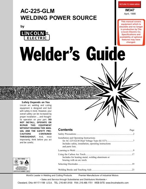
Breaker sizing is not a guessing game; it is a short, logical chain that starts with the welder’s input rating and finishes with the code rule that governs this class of equipment. Walk the chain once and the whole subject stops being mysterious.
The National Electrical Code (NFPA 70) handles welders under Article 630, and the relevant section (630.11) gives the sizing basis. For a transformer-type arc welder, the branch-circuit conductor and overcurrent protection are based on a percentage of the rated input current multiplied by the duty cycle — because the machine does not draw its full rated input continuously. The practical outcome of that code math for an AC-225 is a circuit that supports the 50-amp rated input comfortably.
The industry-standard simplification that most electricians and every sensible welding guide land on: a dedicated 50-amp double-pole breaker on a 230/240-volt circuit. The 50-amp rating covers the machine’s rated input current with room to spare, and because it is a dedicated circuit, there is no other load competing with the welder for that capacity.
The forum answer “you can run it on 30 amps” is not wrong — it is conditionally right, and the conditions are the whole story. Because the AC-225 is a tap-change welder, you can operate it at reduced output (staying on the lower current taps) within a duty cycle that keeps the average draw under what a 30-amp circuit can deliver. There are documented setups using a 30-amp breaker with 10-gauge wire feeding the machine, welding light materials at moderate settings. It works — until someone dials up the heat.
The risks of the undersized path:
The honest recommendation repeats itself: for a machine rated at 50 amps input, a 50-amp dedicated circuit is the safe, correct, code-compliant default, and the 30-amp path is a compromise to be chosen deliberately only by someone who understands the output reduction they are accepting.
A breaker is only one component of a circuit; a breaker alone protects nothing if the wire, the connections, and the receptacle are all sized wrong. This section is the complete circuit recipe for the AC-225, because a proper circuit is built as a system.
For a 50-amp, 230-volt circuit, the code-standard conductor is 6 AWG copper (for most residential and shop runs). The gauge exists to do one job: keep the current flowing without unacceptable voltage drop and without overheating. Undersize the wire and you get the exact failure modes from the previous section — sag, heat, and a shaky arc. The specific gauge can vary slightly with the run length (longer runs may require stepping up to 4 AWG to control voltage drop), which is why the correct phrase is always “6-gauge for typical runs, and check the distance.”
Because this is a 230/240-volt circuit, the breaker must be a two-pole unit — one pole per hot leg, mechanically linked so both open together. A single-pole breaker cannot serve this circuit, and this is one of those details that trips up careful people who are used to household 120-volt circuits.
| Component | Correct Choice | Why It Matters |
|---|---|---|
| Breaker | 2-pole, 50 A, in a panel rated for it | Protects the circuit at the welder’s input rating |
| Conductor | 6 AWG copper | Carries 50 A with acceptable drop and safe temperature |
| Receptacle | 50 A, 250 V rated (e.g., NEMA 6-50) | Matches a 50 A plug; the standard when using the plug-and-receptacle option |
| Circuit type | Dedicated | No other loads sharing the capacity |
| Ground | Properly bonded equipment ground | Protects against faults and is required by code |
Dedicated circuit — why it is non-negotiable: the whole sizing logic assumes the welder is the only load on this circuit. Plug a refrigerator or a bench grinder onto the same circuit and suddenly the 50-amp breaker is protecting 50 amps of welder plus whatever else is running, and the “ampacity” math the design is built on stops being true. A dedicated circuit is not preference; it is the condition the sizing depends on.
The plug-and-receptacle option: the AC-225 can be hardwired or run through a 50-amp, 250-volt receptacle (the common NEMA 6-50 pattern used for welders and some EV chargers). If you choose the plug route, the size of the flexible power feed cord matters too — it must be rated for the current, and the connectors properly torqued.

Installing a 50-amp circuit is real electrical work, and the correct approach starts with the same respect any 230-volt branch circuit deserves. If you are not confident working in an energized panel, the professional-electrician route is not an admission of weakness — it is the correct call. But whether you do it yourself or hire it out, you should know what a proper job looks like, because that knowledge is what lets you check the work.
The honest note: this is the sequence, but the sequence is not a substitute for competence. The code section that governs welders (Article 630), the local amendments, and the panel manufacturer’s instructions all combine to define “correct” in your specific case. When in doubt — and especially if this is your first panel work — the electrician’s advice quoted in the original article is the right one: a professional install is cheaper than the alternative.
Once the circuit is in, the job shifts from building to verifying — and then to the small, predictable issues that every shop circuit develops over years. This section is the practical companion to the installation: how to prove it works, and what to do when the welding stops right.
| Symptom | Most Likely Cause | The Fix |
|---|---|---|
| Breaker trips while welding | Overload (output too high for the circuit), genuine fault, or a worn/loose connection | Reduce tap, verify the circuit has no other load, inspect connections |
| Weak, sputtery arc | Voltage drop (undersized wire or long run) or poor ground/work connection | Verify wire gauge vs. run length; clean and tighten the work clamp |
| Machine hums but no arc | Input or output connection broken, or a tap/selector fault | Check switch, connections, and the stinger cable |
| Breaker runs warm | Undersized circuit for the draw, or tightness issue in terminations | Re-verify sizing; re-torque terminations |
| Weld quality fades mid-run | Duty cycle reached — the machine is overheating by design | Let it cool; that 20% duty cycle is real |
When to stop and call a pro: if a breaker trips repeatedly with no obvious cause, if anything on the circuit smells hot or is discolored, or if you are not certain about any step in the routing — stop. A nuisance trip is annoying; a recurring trip with heat is a fire-signal, and this is the one component in the shop you do not gamble with. The cost of the electrician is trivial next to the cost of the alternative.

Not every AC-225 owner has a shop panel to wire. A large share run the buzz box from a generator at jobsites and farm gates, and that setup has rules of its own — rules worth understanding before you buy a generator the size of a small car on the strength of a forum comment.
The math for generator sizing is straightforward but commonly overlooked. The welder’s input at rated output is 50 amps at 230 volts — that is approximately 11,500 volt-amps (kVA) at full output, before accounting for the machine’s inrush and the generator’s surge capacity. The practical floor for running an AC-225 at its rated range is therefore in the neighborhood of a 10,000–12,500-watt running generator, and for comfortable, repeatable top-end work, larger is better. The FAQ’s “at least 30 kVA” figure is the conservative end of the spectrum and is defensible for the constant, heavy-duty use case, but the everyday reality for most hobbyists and light fabricators sits between those two markers. The rule that beats every number: size the generator for the welder’s input, not the welder’s output, leave surge margin, and check the generator’s own ratings and outlets before connecting.
The pattern in this section repeats the whole article’s theme: the welder’s rated input is the number that builds every safe, undefeatable setup — breaker, wire, receptacle, or generator. Get comfortable reading that number off the manual and the nameplate, and every electrical decision around this machine becomes a calculation instead of a bet.
At rated output — the top of its range running a heavy rod — the AC-225 draws approximately 50 amps of input current at 230/240 volts. That is the number that sizes the breaker and wire. At lower taps, the draw falls well below 50 amps, which is why the machine can run on a smaller circuit at reduced output.
Conditionally. A 30-amp breaker on 10-gauge wire can feed the machine if you stay on the lower output taps and within the duty cycle, welding light materials at moderate settings. It is a compromise path — heavier welding will trip the breaker and the voltage drop will degrade the arc. For the machine’s full capability and clean, safe operation, the recommended setup remains the dedicated 50-amp breaker with 6-gauge wire.
It depends on the welder’s rated input current, and it ranges across the trade. Small 120-volt welders run on 15–20-amp circuits; mid-size 230-volt welders like the Lincoln AC-225 are correctly served by a 50-amp double-pole breaker; large industrial machines may need 60 amps or more. The rule is always the same: read the input amperage on the nameplate, size the circuit to it with margin, and use a dedicated circuit.
You need a generator sized for the welder’s input draw at the output you plan to run. The conservative end of the advice is around 30 kVA; the practical floor for comfortable top-end work on an AC-225 is roughly a 10,000–12,500-watt running generator. Size for the input, leave surge margin, and prefer a generator with clean, stable output for the best arc.
Because the nameplate and the manual describe the machine’s maximum capability, not your average use. The 50-amp input rating is the worst-case draw — the condition the electrical system must safely survive. Sizing the circuit to the rated input is what makes the whole setup safe when a heavy rod or a thick joint finally calls on the machine.
Yes. The entire breaker-and-wire sizing assumes the welder is the only load on the circuit. Sharing the circuit with other devices breaks the ampacity math and invites nuisance trips, voltage drop, and heat. A dedicated circuit is the condition the design depends on, not a convenience.
Yes — a properly rated hardwire connection with the same 6-gauge, correctly terminated conductors is a legitimate install. Many owners prefer the NEMA 6-50 plug-and-receptacle setup for convenience and portability. Either is fine as long as every component is rated for 50 amps and the work meets code.
A properly sized breaker should not trip during normal welding. If it does, the usual causes are: the machine is running beyond the circuit’s assumed duty-cycle profile, a loose or aged connection is causing heat, another load is sharing the circuit, or a genuine ground fault exists. Repeated tripping with warmth or odor is a stop-and-call-an-electrician signal, not a workaround-it signal.
The Lincoln AC-225 is one of the most dependable tools a shop can own, and the breaker question is the one part of owning it that most owners wish came with a friendlier manual. After everything above, here is the entire answer compressed into the form you will actually remember.
The standard, correct setup: a dedicated 50-amp double-pole breaker on a 230/240-volt circuit, 6-gauge copper wire, going to a 50-A 250-V receptacle (the common NEMA 6-50 pattern) or a properly rated hardwire termination, with the machine fed by a correctly rated power cord and a clean, tight ground. That single configuration covers the welder’s full rated output, runs cool under duty-cycle-legal use, and behaves exactly the way the code’s Article 630 math intends.
The reduced-output alternative: a 30-amp breaker with 10-gauge wire can run the machine at reduced taps for light work — but only if you understand the trade you are making: tripped breakers on heavy rods, a weaker arc from voltage sag, and a hotter circuit. It is a deliberate compromise, not a free pass.
The three rules that outrank every number in this guide:
And when the job feels above your comfort level — or the panel is unfamiliar, or the tripping will not stop — the correct answer has not changed since the original article: call in someone who does this for a living. The electrician’s fee is the cheapest insurance in the entire welding shop, and it is the difference between “the wiring is done right” and “the wiring is probably fine.”
Set up the right breaker, wire the circuit honestly, and the buzz box will do what it has always done best — run for decades, weld whatever you ask of it, and never once complain about the circuit that feeds it. That, more than any specification table, is the entire point.
The AC-225 holds a unique place in welding culture, and a quick tour of why helps explain why this article matters more than a generic “breaker size” FAQ. It is not the newest welder, the fanciest, or the most precise. It is the one that shows up in a thousand garage corners because it is indestructible, simple, and capable enough for the work most people actually do — and its electrical appetite is the direct consequence of that old-school design.
The buzz box gets its name from the loud, characteristic transformer hum it produces under load — the unmistakable “buzz” that welds in a small shop. It is a straight AC transformer machine: no inverter switching, no microprocessors, no digital menus. Your grandfather’s generation grew up on these machines, and they still outlive their modern replacements in durability terms by a wide margin. The trade-off for that simplicity is exactly what this article is about: because it is a plain iron-core transformer, it draws a straight, honest 50 amps from the line at rated output — there is no electronics to soften the peak, no fan-assisted efficiency hiding the real draw.
Why this matters for the breaker: modern inverter welders of the same output class often advertise smaller input requirements because their electronics make the current draw more efficient and controlled. The AC-225 makes no such promise. It pours real amperage into the line the moment you strike a heavy arc, and the circuit has to be built to take it without flinching. The person who installs a 30-amp circuit “because my inverter machine runs on 30” is copying a spec that does not apply to this machine.
Walk into any welding shop and you will hear the folklore. The guy who “ran one on 20 amps for years.” The guy whose breaker pops on every third rod. The guy who “upgraded to 60” because 50 “didn’t feel like enough.” Most of these stories are the same story wearing different clothes: someone discovered, the hard way, that the machine’s rated input current is the only trustworthy number. The 20-amp guy was welding tiny rods at the lowest tap his whole life; the 60-amp guy is paying for margin he does not need but has no cause to regret; the popping-breaker guy is the cautionary tale this guide exists to prevent.
The respectful reading: every one of those stories is a data point, and together they confirm the same conclusion. Install the circuit to the nameplate number with margin, and the machine runs; cheat the number, and the machine finds the limit for you. The buzz box has been welding the same way for decades, and the electrical math around it has not changed one bit.
The duty cycle is the most misunderstood number on a welder’s sticker, and it is the number that quietly explains the whole breaker-sizing debate. Understanding it properly turns the “50 or 30” question from opinion into arithmetic.
Duty cycle is the percentage of a 10-minute window the machine can weld at a given output before it overheats. An AC-225 rated at 20% duty cycle at rated output means: at full heat, you can weld for roughly 2 minutes out of every 10 before the machine needs to cool — operating arc-time, not wall-clock time. That does not mean the machine is “for half the work.” It means exactly what it sounds like: the transformer heats up as it delivers, and it needs rest to shed that heat at full output.
Here is where the breaker connection appears: the code’s welder circuit sizing (Article 630) explicitly uses the duty cycle in the conductor and overcurrent math, precisely because the machine does not draw its full input current continuously. The practical consequence is that a 50-amp-rated input machine can, under the code’s calculation, be served by a circuit with a nominal rating below 50 amps in some configurations — which is where the “30 amp” camp gets its ammunition. The same math is why the 50-amp recommendation is not overkill for the owner who uses the machine modestly.
Picture the circuit as a budget. The machine’s peak spend is 50 amps (a heavy rod at the top tap, exactly during the arc). Its average spend over a 10-minute window at 20% duty is much lower — 20% of 50 is 10 amps of average if you could average cleanly, though real welding is burstier than the math. The breaker has to hold the peaks (so it must not trip at 50 A, hence 50 A plus margin is the calm choice), and the wire has to carry the peaks without overheating (hence 6-gauge). A 30-amp circuit can survive if the operator never sustains the high-tap peaks — the budget stays under its limit. The moment a heavy rod at the top tap arrives, the 30-amp budget is blown and the breaker opens.
The decision rule that respects the duty cycle: if you will ever use the machine at the top of its range — and most owners eventually do, on a thick plate or a structural job — give it the 50-amp circuit and stop negotiating with yourself. If you are committed to light-tap welding only, the 30-amp path is defensible but must be enforced by your own discipline, which is exactly the kind of self-reliance that gets tired at hour six on a Friday.
Most breaker discussions — including the confident forum posts — stop at amperage. The second variable, the one that silently ruins real-world performance, is voltage drop, and it deserves a section of its own because it is the difference between a “great setup” on paper and a “weak arc” in the booth.
Every conductor has resistance, and resistance converts current flow into heat and voltage loss. As the current travels from the panel to the receptacle and through the power cord, a fraction is lost to that resistance — the longer the run and the thinner the wire, the bigger the loss. For a welder, the result is a machine that sees a lower line voltage than the panel delivers, and a welder that responds to low voltage exactly the way you would expect: weak arc, poor penetration, sputters, and a coarse feel that most people misdiagnose as a bad rod or a failing machine.
The numbers that matter: a properly sized 6-gauge run of moderate length keeps the drop in the single-digit-percent range, which is generally fine. Stretch that run to 100 feet, or drop to undersized wire, and the drop climbs into the range where the arc integrity suffers visibly. The rule of thumb used by electricians and welding-writers both: the longer the run, the heavier the wire needs to be — and a long run on “exactly the code minimum” may be short by one gauge.
The takeaway that unifies the whole article: correct breaker size and correct wire size are two halves of the same decision, and neither one works without the other. A 50-amp breaker on 12-gauge wire is a fire waiting in the panel; a 50-amp breaker on 6-gauge wire stretched across a long, saggy run delivers a lovely breaker and a miserable arc. Size the pair together, to the nameplate, with the actual run in mind — and the buzz box finally gets what it has been asking for all along.
Before and during any electrical work on a shop circuit, the difference between a pleasant afternoon and an incident is the tooling in your hand and the discipline behind it. This section is the toolkit and the verification habits that make the installation section work in practice.
The classic mistake in panel work is the confident assumption — “I flipped the main, it’s dead” — followed by a surprise. The habit that kills the mistake is cheap and non-negotiable:
None of this tooling makes a novice a professional. The genuinely wise position is the one the article’s original advice reaches: if the panel is unfamiliar, the code is ambiguous, or the installation involves more than a straight run — that is the moment to hire. The instruments are the difference between a safe DIY job and a dangerous one, but the judgment about whether to DIY at all is a separate skill, and the cheaper version of it is the electrician.
The whole toolkit philosophy wraps back to the theme of the article: respect the machine’s appetite, verify what you cannot see, and never let certainty outrun evidence. That is how you size a breaker — and how you sleep after the panel cover goes back on.
A properly installed circuit does not stay properly installed by magic. Circuitry drifts, connections loosen, panels age, and — the most predictable variable — the person using it forgets the rules. The long-haul section is the maintenance calendar and the mindset that keep a buzz box running for its full decades.
| Interval | Check | Why |
|---|---|---|
| Before each heavy weld session | Inspect plug, receptacle, cord, and ground clamp for damage | A nicked cord or loose clamp invites heat and shock |
| Monthly | Panel: flip the welder breaker manually to confirm it still operates; inspect for warmth or odor on high-use days | Mechanical breakers get lazy; heat is the early warning |
| Annually | Torque-check terminations; re-verify voltage at the receptacle; inspect the whole run for wear | Connections loosen with thermal cycling; catches the slow creep |
| After any trip or surge | Re-test the breaker, inspect connections touched by the event | A trip is a clue; the cause deserves a look |
The discipline that serves this area of welding better than any checklist is a simple mental habit: treat the electrical setup the way you treat the weld — inspect before use, question the unexpected, and fix the root cause rather than the symptom. A breaker that trips once and never again is a story to remember; a breaker that “always trips on that rod” is a system telling you the truth, and the truth is that the circuit, the tap, or the operator needs a change.
The other half of the long-haul mindset applies to the operator. The person who installed the 30-amp compromise for light work must remember the compromise when a neighbor asks to “weld up a quick trailer bracket” — because the neighbor will not know the circuit’s limits, and the trip-and-blame cycle will follow. Write the circuit rating on the panel, label the receptacle, and take thirty seconds to tell anyone who uses the machine where the honest limit lives. Machinery respects labels; surprise does not.
The final thought for the whole article: none of this — breaker size, wire gauge, voltage drop, duty cycle, inspection — is complicated separately. Each piece is one clear decision. What makes the buzz box’s electrical setup feel overwhelming is only the number of pieces arriving at once. Handle them one at a time, on the basis of the nameplate and the code, and you will have a shop circuit that serves the machine faithfully for the decades the AC-225 has left in it.
The reason every breaker question about this welder attracts so many confident, contradictory answers is that the machine has been made and discussed for decades, and the manual, the code, and the folklore each carry a slightly different emphasis. Settling the scores once and for all is the most useful thing this section can do.
Lincoln’s documentation for the AC-225 specifies a 230-volt input and defines the rated input current at 50 amps at rated output. It shows the machine connected to a properly rated circuit, and — like every responsible welder manual — it instructs the owner to install adequate input power and, where the work calls for it, to have a qualified electrician handle the connection. The manual is not in the business of hosting a debate about 30 versus 50; it publishes the rating and assumes a competent install to that rating. Anyone who tells you “the manual says 30 amps” is reading a number that is not in the manual.
Article 630 of the National Electrical Code is the actual legal authority the manual implies. Its welder-circuit sizing rules use the rated input current and the duty cycle to produce the conductor and overcurrent sizing — and it is that math, not a forum, that yields the “dedicated 50-amp circuit with 6-gauge wire” recommendation for the full-capability install. The code is the real referee, and the code’s answer for an owner who wants full rated output is unambiguous.
The forum is where the nuance lives — and where it detaches from the manual when misquoted. The legitimate forum point is real: a tap-change machine running at low taps can live on a smaller circuit, and plenty of shops do it every day. The same forums also host the person who ran a buzz box on a 20-amp circuit for a decade “without a problem,” because every weld they made was at the lightest end of the machine’s range. That survivorship story is true, and it is also not evidence that the machine is rated for 20 amps — it is evidence that the machine is forgiving enough to run below its catalog rating when the work is light.
The scores, settled:
The one-sentence resolution: everyone is describing the same machine from a different height — the manual from rated output, the code from engineering math, the forum from lived experience at the light end. Use the rated input as the anchor, take the forum’s nuance as texture, and let the code’s arithmetic cast the deciding vote on size.
All the electrical correctness in the world serves one purpose: letting you strike an arc and weld well. This section closes the loop by pairing the properly sized circuit with the technique that makes the AC-225 deliver its best — because a great circuit feeding sloppy technique still produces a poor weld, and the two skills belong together.
The difference between welding on a correctly sized circuit and on an undersized one is not subtle to the welder, even if both “produce” beads. On the right circuit, the arc stabilizes quickly, the rod burns predictably, the bead lays smooth, and the breaker sits quietly in the panel. On the wrong circuit, every weld is a negotiation — sputter, sag, a breaker that opens mid-bead on thick work, and a growing suspicion that the machine is “tired.” None of that is the buzz box. It is the circuit, and now it is fixed.
The closing technique note: the AC-225 rewards consistency. A stable heat, a steady travel speed, and a clean work clamp will produce welds that surprise people who expect the old machine to be “basic.” Set it up honestly — dedicated 50-amp circuit, correct wire, right rod for AC, clean ground — and the buzz box turns from a cliché into the reliable workhorse its reputation always promised.
Every recommendation so far has been grounded in specifications and code. But welding is a craft practiced by real humans in real buildings, and the way professional shops actually wire these machines carries its own lessons worth collecting. These are not authoritative overrides — they are the texture that connects the engineering to the floor.
The typical professional fab shop does not move its buzz box around. It builds the welder a permanent station: a dedicated 50-amp circuit from the panel, 6-gauge run to a fixed receptacle, a short heavy power cord, and a labeled circuit in the panel directory. The station gets the welder the best possible electrical life because the wiring was planned once, sized right, and never asked to bend.
The field crew runs the same machine from a generator, and their pattern is instructive: the generator is sized to the welder’s input draw, the leads are short and heavy, and the ground/bonding rules are handled deliberately — not improvised. Their experience confirms what the sizing section argued: generator-fed operation fails for exactly the same reasons a stolen 30-amp circuit fails, and it succeeds for the same reasons a dedicated station succeeds.
The most common real-world setup is the garage: a 30-amp dryer-style circuit (or a spare 240-volt run from the panel) feeding a machine that mostly welds rust repair, gates, and light plate. The garage owner who understands the machine runs it at the lower taps, keeps the run short, and lives with occasional trips on adventurous days. The garage owner who does not understand it blames the machine, overspends on a “better welder,” and repeats the cycle with the new one. The lesson is worth the admission: the machine is almost never the weak link in an undersized circuit — the sizing was.
Three habits separate the shops that never think about their buzz box’s electrical life from the ones that fight it weekly:
The real-world summary: there is no mystery in professional wiring. There is only the same decision made well: a circuit sized to the rated input, kept dedicated, kept clean, and labeled for the person who inherits it. Build that pattern and the buzz box — this one or the next — never becomes an electrical topic again.
Correct breaker sizing protects the circuit. The welder’s protection — and the shop’s — extends beyond the panel, and the final section of the practical guide closes the loop with the electrical safety that belongs in every buzz box owner’s head.
Every layer of this guide — the 50-amp breaker, the 6-gauge wire, the dedicated circuit, the voltage-drop check, the labeled panel, the tested setup — exists for one reason: so that the welder’s arc is the only thing in the room that runs hot. The circuit silently does its job, the breaker stands guard without being asked, and the person at the booth concentrates on the weld. That is the entire and correct goal of electrical setup.
The last paragraph, saved for the simplest truth: the Lincoln AC-225 has earned its reputation over generations by being simple, tough, and endlessly repairable. It asks one thing in return — a power supply honest to its rating. Give it the dedicated 50-amp circuit it was designed for, wire it clean, and treat the panel work with the same respect you treat the weld, and the buzz box will spend the next decades the exact way it spent the last ones: running, humming, and welding whatever you put in front of it. That is the deal, and it has never changed.
A final quick-reference card to pin beside the panel: Lincoln AC-225 — 230 V input, 50 A input at rated output, 20% duty cycle at full heat, dedicated 2-pole 50 A breaker, 6 AWG copper, 50 A 250 V receptacle (NEMA 6-50), reduced-output operation possible on 30 A/10 AWG at low taps only, generator sized to input draw (10–12.5 kW running for comfortable top-end work). Check the manual, label the circuit, keep the connections tight, and call the electrician the moment reality no longer matches the label.