Arc Welding for Dummies: The No-Nonsense Beginner’s Guide to Your First Weld
Arc welding for dummies made simple: processes, gear, safety, settings, first-weld steps, common mistakes and fixes. Start welding…
READ ARTICLE →Derek bought a used transformer welder at an estate sale, got it home, and read the number that was staring at him from the front panel: 225 amps. That, he decided, was the answer to the question he had not asked yet. He drove to the hardware store, bought a 100-amp double-pole breaker because it was bigger than 225… no, because it was the biggest one that worried him the least, and he bolted it into his panel. The welder ran great — for about an hour, until the wire feeding the new breaker got so hot the insulation softened, and a section of it slumped against the metal panel below the terminals. He was lucky it shorted to ground instead of through his hands. When I saw the setup, the confusion was easy to explain: he had sized the breaker to output amperage, 225 amps, instead of to input amperage, which for that machine is roughly a third of that number. It is the most common electrical mistake in all of home welding, and it starts with a perfectly understandable reading error.
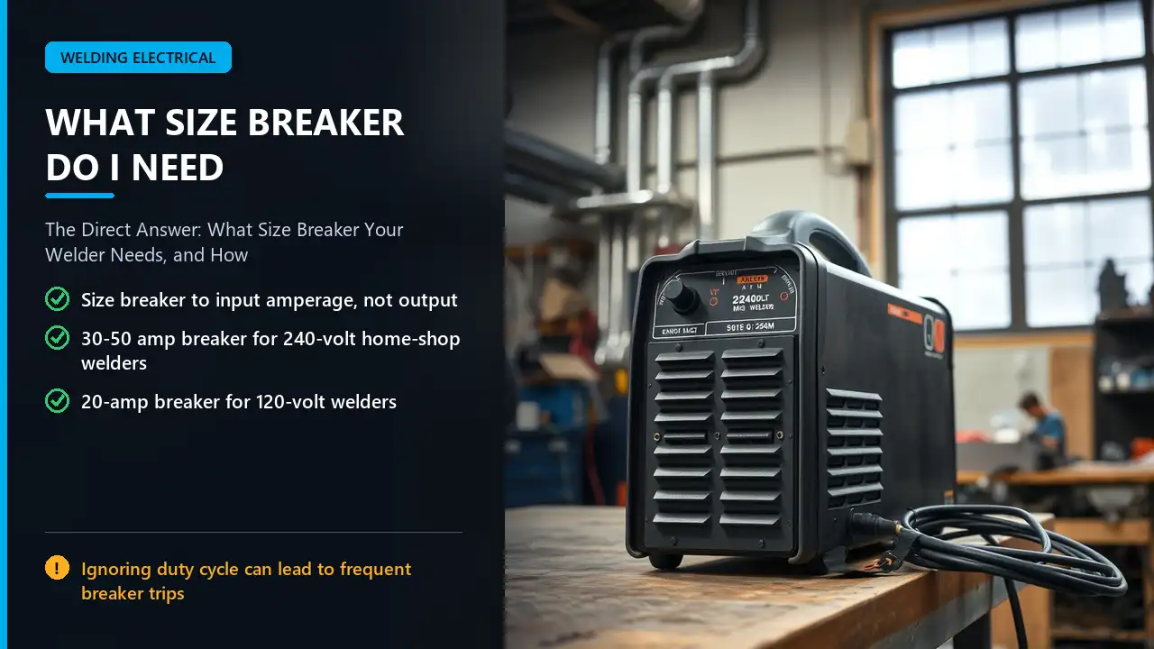
Here is the answer, stated plainly so nothing buries it: size the breaker to the welder’s nameplate input amperage — never to the output amperage stamped on the front of the machine. For most 240-volt home-shop welders that lands on a 30, 40, or 50-amp double-pole breaker. For 120-volt welders it lands on a standard 20-amp breaker. Duty cycle, wire gauge, and what else shares the circuit nudge that number up or down, and the National Electrical Code sets the floor.
What follows is the full picture: how to find input amperage when it is printed and when it is not, why each welder type tends to land where it does, how duty cycle changes the math, what the code requires by number, the wire that has to ride behind the breaker, and the mistakes that trip people up when they stop reading and start installing. Derek’s story has a good ending — we pulled the 100-amp breaker, matched the machine to a correctly sized double-pole breaker and proper wire, and the welder has run hot for years since without a single trip. He tells the story on himself now. Your version should start with the right number instead.
Quick Note: When a breaker keeps tripping, the reflex is to install a bigger breaker “to give it room.” That is the wrong move nearly every time, and it is exactly how wire ends up carrying current it was never rated for. The cause comes first. The breaker size is a solution, not a habit.
Match your machine to the nearest row, then confirm with the nameplate before buying anything.
| Welder type | Typical output range | Typical input at 240V | Recommended breaker | Common receptacle |
|---|---|---|---|---|
| Small 120V MIG / flux-core | 90–140A | 12–18A at 120V | 20A, single-pole | 5-20R |
| Dual-voltage MIG, 180A class | 30–180A | 22–24A at 240V | 30A, double-pole | 6-30R / 6-50R |
| 240V MIG, 200–210A class | 30–210A | 28–32A | 40A, double-pole | 6-50R |
| 240V TIG with AC/DC | 5–250A | 30–42A | 40–50A, double-pole | 6-50R |
| Stick / transformer “buzz box” | 225–250A AC | 32–48A | 50–60A, double-pole | 6-50R or hardwired |
Read the nameplate before you read the front panel. The sticker on the back or side of the machine states input voltage, input amperage at rated output, and often the recommended overcurrent protection directly. When the manufacturer prints a suggested breaker size, the argument ends — that is the number. Our guide to the right outlet for your welder pairs with this one, because the outlet, the wire, and the breaker are one matched system and none of them works correctly without the other two.
Pro Tip: Take the whole nameplate photograph, not a note. The numbers get transcribed wrong in a hurry when you are writing on a sweatshirt sleeve with a grease pencil.
The amperage that makes people pick breakers — 140, 180, 225, 250 — describes what the machine delivers to the electrode, not what the machine pulls from the building. Those two numbers speak in different currencies. Welding happens at low voltage and high current; roughly 20 to 40 volts at the arc, sometimes less. The building supplies high voltage and comparatively low current: 120 or 240 volts. The welder’s transformer or inverter converts the first into the second, and in the bargain the current changes sides.
An example makes the gap concrete. A welder rated 200 amps of output at, say, 20 arc volts is delivering about 4,000 watts to the weld pool. Add inefficiency — transformer losses, fan motor, control circuits — and the machine may need roughly 5,000 watts from the wall. On a 240-volt circuit that is about 21 amps of input. So a 200-amp welder’s input sits around 20 to 30 amps, nowhere close to its output rating. That is why a machine stamped “200A” belongs on a 40-amp breaker at most, and a “225A” buzz box lands closer to 50. The same machine on 120 volts would need double the input current, which is exactly why big welders run on 240 volts and not from a wall socket.
The topic gets a full treatment in our breakdown of how many watts a welder uses, because the same input-versus-output confusion drives the generator sizing questions people ask constantly. The short version for breaker work: the input current on the nameplate is the only current a breaker can see, and therefore the only current it is sized for.
Short Note: Inverter machines are slightly more power-efficient than transformer machines at the same output, drawing a bit less input current. The difference is real but modest; the nameplate still overrides any rule of thumb.

The information is hiding in plain sight. The nameplate is the first stop — the same sticker that carries model and serial numbers. On many machines it lists “input volts” and “input amps” or “primary current” side by side, sometimes for multiple voltage settings. The owner’s manual repeats it in the specifications chapter. New inverter machines often print a small chart showing input amperage at different output settings. If none of that exists because you bought the welder off the back of a trailer, calculate it from watts the way the generator crowd does: divide input power in watts by input voltage. 6,000 watts on 240 volts is 25 amps. On 120 volts it is 50 — a reminder why the voltage side of the equation matters as much as the machine itself.
Pro Tip: Match the input current at the machine’s rated output, not its maximum momentary setting. The rated figure is what the code and the manual assume, and it is usually printed in bold because it is the number the building cares about.
MIG, TIG, and stick machines draw different current for the same model name, because the processes work differently at the arc and the electronics differ behind the faceplate. Understanding the profile of your process keeps the breaker choice from feeling like guesswork.
MIG machines are the most common home-shop fixture and the best-behaved from a circuit standpoint. A MIG arc is steady, the wire-feed motor adds a modest load, and duty cycles at hobby output are gentle. A 120-volt MIG in the 140-amp output class typically draws 12 to 18 amps and wants a 20-amp dedicated breaker. Dual-voltage 180s run happily on 30 amps of 240-volt infrastructure. The 200-amp-plus units — the ones that can actually weld a quarter-inch plate all day — push input into the low 30s and land on 40-amp breakers. If you are choosing a machine with electrical constraints in mind, our guide to the best MIG welders for beginners lists input requirements next to each pick.
TIG machines look similar on paper and behave differently in the wall. An AC/DC TIG unit carries the high-frequency generator, the gas solenoid, and a control board that draws power continuously even when you are not welding. Their output ratings run to 200 or 250 amps for aluminum work, which pushes input current into the low 40s at the top end of the range — squarely on a 50-amp breaker. A pure DC TIG used only for steel sits lower, but for an AC/DC aluminum-capable machine, plan the circuit generously; the high-frequency start and the compressor surges of the arc have a way of punishing a circuit sized at the very edge of the machine’s rating. Our best TIG welders for aluminum roundup describes the power side of each unit.
Stick machines are the reason this article exists. They are current-hungry, and the arc is the least forgiving in welding — a stick welder dipping and shorting spends part of every pass creating momentary current spikes. Old transformer buzz boxes, like the beloved Lincoln 225 arc welder and its relatives, pull 30 to 48 amps on 240 volts at full output, which lands them on 50-amp breakers, sometimes 60 for genuinely hungry units. Their high duty cycles at moderate settings mean they sustain that draw on long runs of rod. Handing a big transformer machine a breaker sized by “whatever the welder on TV said” is a one-way ticket back to the panel with a melted terminal — which is why our buzz-box welding article spends as much time on the power question as on the beads.
Quick Note: Stick welding’s current spikes are why a stick machine benefits from headroom on the breaker more than any other type. If the nameplate says 40 amps and you are between breaker sizes, the 50 is the friendlier choice — provided the wire is sized for it.
For 120-volt welders the answer is nearly always the same: 20 amps, single-pole, dedicated, with the wire sized to match. Machines in the hobby class — flux-core units around 90 to 130 amps, small MIG/TIG combos — draw well under 20 amps and run with room to spare on a 20-amp circuit. The breaker is effectively protecting the wire (12 AWG on a 20-amp circuit) against faults, not riding along at the machine’s continuous draw.
Can a 15-amp breaker work? On paper, for machines whose input never reaches 15 amps, yes. In practice it leaves no margin for startup surge, voltage drop on a long extension, or the winter cold making the wire feed work harder. Manufacturers of 120-volt welders almost universally recommend a 20-amp dedicated circuit even when the machine draws only 12 or 13, because they know the real-world conditions under which the machine runs. Follow them. A 20-amp breaker, 12 AWG wire, and a 5-20 receptacle is the correct 120-volt welder circuit, full stop. Our coverage of welding shop safety treats the electrical supply as part of the workplace, which it is.
Short Note: If your 120-volt welder keeps tripping a 15-amp breaker at moderate settings, jumping to a 20-amp breaker without checking the wire is a gamble. Verify 12 AWG behind the receptacle first, then the swap is legitimate.
Most 240-volt welders fall into one of four breaker sizes, and the nameplate tells you which:
| Breaker size | Wire (copper) | What belongs on it | Typical input range |
|---|---|---|---|
| 30A double-pole | 10 AWG | Dual-voltage 180A MIG at full power, light TIG | 20–24A |
| 40A double-pole | 8 AWG | 200A class MIG and DC TIG, mid-size transformer units | 25–32A |
| 50A double-pole | 6 AWG | Home-shop standard — most AC/DC TIG and stick machines | 33–40A |
| 60A double-pole | 4 AWG | Heavy single-phase transformer welders, industrial machines | Above 40A |
The 50-amp breaker deserves its reputation as the workhorse of home welding. It covers the widest spread of machines, its 6 AWG wire is modestly priced, and a 6-50 receptacle is the most common welder outlet in North America by a wide margin — which means an outlet already exists in a surprising number of used shops. If you are building from scratch and intend to grow into larger equipment, running 6 AWG on a 50-amp breaker the first time is cheaper than pulling cable twice. The 30-amp circuit saves real money for machines that genuinely belong on it, and it stays legal and clean for the 180-class dual-voltage machines that spend their whole lives on 240 volts. Buy an elevator, and it is better to fit the room than the room to the elevator — the same reasoning applies when a small dual machine is sized for life on a 30.
Pro Tip: Electricians are allowed to oversize connectors slightly but never the breaker relative to the wire. When someone quotes you a “40-amp circuit with 6 AWG,” that is fine; a “50-amp circuit with 10 AWG” is not, and no amount of opinion changes it.
Duty cycle is the welder’s time limit — the fraction of a ten-minute window a machine can weld continuously before its thermal protection wants it to rest. A 100-amp-setting MIG at 60% duty cycle runs six minutes straight, then rests four. The number matters for breaker sizing because the breaker has to live with the machine’s average and peak current, not just the peak. A welder running at a low duty cycle (say 20%) draws hard in short bursts and lets the circuit cool between passes, which is forgiving. A machine at 100% duty cycle draws continuously, and the circuit never gets a breather — the wire stays hot, and the breaker’s own thermal element stays warm, which makes it trip more easily over time.
In practice, most residential welding happens at duty cycles low enough that a nameplate-sized breaker is comfortable. The danger shows up in repair work and production: hours of drag-out welds down a long seam, a stick machine hammering rod after rod, or an automated setup running beads all day. Under that kind of sustained load, a welder whose nameplate says 30 amps belongs on a circuit sized with honest headroom — the 40 or 50, matched with the correct wire — because the breaker’s rating is a continuous rating and the machine is now running more continuously than its duty cycle implies. Our article on increasing welder duty cycle covers the machine-side fixes that help, but no amount of fan airflow changes what the building’s wire is rated to carry.
Important: Duty cycle is always stated relative to ambient temperature and a specific current setting. A machine run at half its rated output can often exceed its printed duty cycle; a machine run at maximum output will often fall short. The circuit planning charts the same way — pessimism on the input side is the safe direction.
Here is where the theory stops being academic. A welder at 60% duty cycle runs six minutes on, four off, and a correctly sized breaker rides through that pattern forever without complaint. A welder at 100% duty cycle — think automated turntable welds, long structural seams, or a repair shop stacking joint after joint — draws continuously, and the building responds. The wire in the wall approaches its full operating temperature and stays there. The breaker, which is also a thermal device, runs warm and gets slightly easier to trip. The machine’s own over-temperature shutdown starts chiming in earlier on a hot afternoon, stacking a thermal management problem on top of an electrical one. In shops that run heavy production, that combination is precisely why circuits get overspecified by a size even when the nameplate could “get away with” less — the wiring has to survive the realistic worst case, not the brochure duty cycle.
Pro Tip: If your shop is a production environment where machines weld for hours, budget the circuit for the machine’s continuous draw at the setting you actually run, not the duty cycle test conditions. That one habit prevents more nuisance trips than any breaker brand on the shelf.
Here is the entire calculation, reduced to four steps, with a worked example in case you need to check the arithmetic yourself.
Step 1: Identify the input voltage. The nameplate states whether the machine runs on 120, 240/208, or both. This number decides the whole shape of the circuit — a 200-amp machine on 240 volts draws half the current of the same machine on 120, which is why nobody runs big welders from wall sockets.
Step 2: Find the input amperage at rated output. It is printed on the nameplate — usually as “input current” or “primary current @ rated output.” If it is missing, compute it: divide the rated input watts by input voltage. Example: a machine rated 5,000 input watts at 240 volts draws 5,000 ÷ 240 = 20.8 amps.
Step 3: Apply the sizing rule. For a welder whose nameplate says 20.8 amps, the code’s approach lands you on a 30-amp breaker: the breaker must be rated for the current, and you pick the next standard size that fully covers the machine’s draw with margin for surges. The 125% continuous-load multiplier used for many household appliances is the general default, but welding equipment has its own rules (NEC Article 630) that account for intermittency — in common installations, a 30-amp machine nameplate regularly lands on a 30-amp breaker and correct wire. When in doubt, the next size up with matching wire is never a safety problem; the problem is only ever the other direction.
Step 4: Match the breaker to the wire. The breaker is the wire’s protector. 20-amp circuits use 12 AWG copper, 30-amp use 10 AWG, 40-amp use 8 AWG, 50-amp use 6 AWG. If you up the breaker, up the wire in the same transaction, or you have built a de facto fire hazard. For a full walkthrough of the conductor side, our guide to wire gauge for 30-amp 220-volt circuits is the companion piece to this article.
Quick Note: Run the same four steps for the outlet: the receptacle rating must equal the breaker rating. A 30-amp breaker feeding a 50-amp receptacle is legal only under narrow conditions; a 50-amp breaker feeding a 30-amp receptacle is a risk, because a 30-amp outlet will happily try to carry 50 amps until it melts.
The National Electrical Code is the floor, not the ceiling, and for welders it lives in its own article because welding equipment’s load profile does not fit the general household rules.
NEC Article 630 is written for electric welders. It sets out conductor sizing and overcurrent protection for welding circuits, and it rests on the reality that welders run intermittently. Under Article 630, branch-circuit conductors can generally be sized on the welder’s rated primary current, and overcurrent protection can be selected at the next standard size above the machine’s input rating in many cases — which is why a 30-amp-nameplate machine on a 30-amp breaker and a 50-amp transformer welder on a 50-amp breaker are both routine, code-compliant installations. The article also recognizes that conductors feeding welders may be smaller than general-purpose rules would allow because duty cycle limits sustained current — but that permission is granted to wiring sized for the machine, not to wiring that predates it.
The wire behind the breaker has to carry the ampere rating printed on the breaker. The NEC ampacity tables are the authority on that match. 12 AWG copper carries up to 20 amps in typical installations, 10 AWG carries 30, 8 AWG carries 40, 6 AWG carries 50, 4 AWG carries 60-plus — and the breaker is allowed to protect exactly what the wire can carry, never more. The National Fire Protection Association publishes the NEC and its referenced standards, and the full text of the welding article is the place to check the detail if you are doing the work yourself. Commercial shops add the OSHA layer — OSHA’s welding standard governs hot work and general workplace electrical safety, and shops must follow both electrical and fire-prevention rules at once.
Manufacturers spell out the intended supply in the manual. Welding equipment builders publish the recommended circuit and overcurrent protection for every machine they produce. Lincoln Electric’s owner’s manuals, like those of every serious manufacturer, print the input requirements table with the breaker recommendation included — cross-check your model’s page with this article and the answer is closed. The engineering standards that those manuals are written against come from the American Welding Society, whose published AWS standards library is the deeper reference if you want the procedural side of how welding equipment is specified and rated. Between the NEC, the manufacturer’s manual, and the nameplate, there is no remaining mystery about the number.
Listed breakers and tested devices. The certification marks on the breaker itself matter, because a breaker’s trip behavior is a tested characteristic, not a marketing claim. Devices carrying listings from recognized testing laboratories such as UL have verified trip curves and short-circuit ratings, and using listed breakers matched to a listed panel is the baseline manufacturers and inspectors both assume. A breaker without those credentials is an unknown quantity in the middle of the most important safety device in the building — not a place to save money.
Pro Tip: Local code wins. Some jurisdictions amend Article 630, some require permits plus inspection for new welder circuits, and some inspectors want a load calculation on the panel. Ask your building department before the work; a phone call is cheaper than a failed inspection.
The reflex to buy larger is understandable — the word “headroom” sounds good — and the reflexes against it are equally understandable. Both directions have costs, and only one of them is ever a safety problem.
| Choice | Pros | Cons |
|---|---|---|
| Larger breaker (with matching wire) | Headroom for surge current and future machines; fewer nuisance trips at peak draw; sustained-duty comfort | Higher part cost, larger wire, a wasted margin if the machine is small forever |
| Precisely sized breaker | Lower cost, exact protection, lighter wire for the run | No margin for spikes, extras on the circuit, or a future upgrade — and it trips exactly when you cannot afford the interruption |
| Oversized breaker on undersized wire | None — this is a risk, not a strategy | The wire is the weak link and the breaker cannot see it; insulation cooks until something fails |
The same logic runs in both directions for the machine side. A welder connected to a breaker far below its draw will trip mid-pass, and a welder connected to a breaker far above its draw lives with no protection margin at all — the machine’s own thermal protection runs for a long time before the breaker ever moves. The sweet spot is the nameplate recommendation, or one size larger with matching wire when the machine surges or the run is long. The trade table above is why professional shop wiring consistently lands on “generous but matched”: matched means every component carries the same rating, and generous means the whole set is a size above the bare minimum.
Short Note: “The breaker never trips” is not automatically praise. A breaker that never trips is protecting correctly only if it would trip on a genuine fault. Test yours with the test button on an annual schedule; it is a five-second habit.
I keep coming back to a job from a few years back — a small fabrication garage with three welders sharing what its owner described as “the big circuit.” The panel handle was marked 60; the wire was 10 AWG; the machines were a MIG, a small TIG, and an old transformer stick unit, all wired into a junction box together. The owner had stopped tripping breakers months earlier by “upgrading” the handle, and the wire had been quietly reaching temperatures the insulation was never meant to see in the space between two studs. What caught it was not the panel — it was the occasional smell of hot terminal screws from the junction box behind a workbench.
The fix took an afternoon once someone took the panel seriously: separate circuits sized to each machine on its own breaker and its own wire, a proper subpanel dropped into the shop, and the 60-amp handle reassigned to a feeder it could actually protect. The machines behaved better than they had in years, because each one finally had a supply that did not sag whenever the other two woke up. Stories like this one are why shop electricians talk about load calculations the way they do, and why every serious discussion about welder power starts with the same sentence: the breaker protects the wire, the wire feeds the machine, and the machine draws what its nameplate says it draws. Nobody gets to negotiate those three facts.
If you are running machines in parallel — two welders in one shop, or a welder and a compressor — the load math compounds, and the subpanel conversation becomes more than a nicety. Our piece on three-phase to single-phase conversion walks through the supply-side planning for shops that outgrow a single breaker.
Important: Fuse boxes and old panels change every assumption in the room. A vintage screw-in fuse is a thermal device and a breaker is a magnetic-plus-thermal device with a different trip curve; slotting “the next size up fuse” into an old panel is how houses burn. Old equipment deserves a look from a licensed electrician before it feeds anything as hungry as a welder.
Mistake one: sizing from output amperage. The 225-amp-per-output mistake that opened this article. Fix: read the input amperage on the nameplate; it is one line lower on the sticker.
Mistake two: ignoring peak draw. Some inverters draw a short startup surge above their continuous current, and transformer machines inrush on power-up. Backing the breaker up one standard size with matching wire covers the transient without compromising protection.
Mistake three: matching the breaker to everything else on the panel. A welder sharing a branch circuit with lights, a compressor, or a heater is the setup where trips are actually informative: they are telling you the circuit is overloaded, not the welder. The fix is a dedicated circuit, exactly as covered in the welder outlet guide.
Mistake four: buying a breaker brand that does not match the panel. Panel manufacturers state which breakers are listed for their load centers, and inspectors know. A mismatched breaker can fail to seat, trip at the wrong current, or never trip at all.
Mistake five: forgetting that the wire has to change when the breaker does. The most common of all errors, because the breaker is visible and the wire is not. Every square inch of that cable matters.
Mistake six: double-tapping. Landing two conductors on one breaker terminal to “make room” violates the listing of most residential breakers and creates a loose connection point that will over time. The answer is a proper subpanel or a correct tandem breaker, never a pinched double.
Quick Note: When a breaker trips repeatedly at exactly the same current, suspect the breaker’s thermal element before the machine. Trip-at-the-same-number behavior spreading across time usually points at the device, not the load — a licensed electrician can verify with a meter in ten minutes.
Can two welders share a breaker? Technically yes, in the same way two cars can share one parking spot: it works only when they are never there at the same time. If the combined input amperage of the welders stays under the circuit rating, and only one operates at a time, a shared circuit is not automatically illegal — but it is fragile. The moment a second machine starts while the first is mid-pass, or the compressor cycles in, the arithmetic changes and the breaker becomes the referee again. Since the cost difference between one 50-amp circuit and two dedicated circuits is usually measured in cable and conduit rather than in a new panel, the professional answer is almost always separate circuits, each sized to its own machine.
There is a legitimate version of sharing: machines dedicated to different stations that genuinely never run simultaneously, wired on a circuit sized for the larger machine’s input plus a safety margin. That setup works, and it is common in small rigs. The unsafe version is piggybacking adapters until the garage looks like a plug blender. If you find yourself asking whether the third machine “will be fine on the same breaker,” the honest answer is that you already know the safe answer and you are hoping someone will talk you out of it. Nobody reasonable will.
Pro Tip: Keep a written breaker map in the shop — machine, breaker number, and circuit contents. It turns a future grounding fault from a hunt through the dark into a two-minute fix, and it makes the load question answerable by anyone who works in the shop.
Every foot of copper eats a little voltage, and the longer the run from panel to receptacle, the more the machine at the end starves. Voltage drop is the quiet failure mode of welder circuits: the breaker is sized correctly, the wire is rated for the amperage, and everything still goes wrong — because the machine is receiving 218 volts instead of 240, and an undervoltage welder draws more current to compensate, which pushes the circuit back toward the very overload the sizing was meant to avoid. It is a feedback loop, and it is why long runs deserve a conductor one size larger even when the ampacity table technically permits the smaller gauge.
The common engineering target is to hold branch-circuit voltage drop to about 3%, with feeder plus branch totaling no more than about 5% at the appliance. Translate that into a workshop and the picture gets practical fast. On a 240-volt circuit, 3% is about 7.2 volts. Ten-gauge copper loses roughly a volt per 30 feet at 30 amps of load; twenty-gauge… the point is that a 60-foot run at 30 amps on 10 AWG can shed well over a volt per leg, and the machine feels it. Short runs — under about 25 feet — rarely matter. Runs from a panel at one end of a house to a shop at the other end absolutely do, and the fix is a conductor size larger on the same mechanical layout. The math is the same one used in every feeder calculation, and it is explained step by step in our guide to wire gauge for a 30-amp 220-volt circuit.
Upsizing wire does not change the breaker rating — a 50-amp breaker with 4 AWG instead of 6 AWG is still a 50-amp circuit, just a cooler, more honest one. The breaker stays at the rating the machine needs; the wire grows to guarantee the voltage reaches the machine at full load. Three situations justify it without debate: runs past a hundred feet, runs through hot attics or buried conduit with derating factors, and circuits that feed machines at the top of their rating where sagging voltage makes the arc unstable. In every case the extra cost is a few dollars a foot at most and the benefit is machine performance you can feel in arc stability. If you are feeding a shop from a garage panel that sits literally on the other side of the house, budget for the larger conductor while the trench is still open.
Short Note: Voltage drop is invisible until it is expensive. The symptom is usually a machine that runs fine for an hour and then grows weak — because the dropping voltage raises current draw until a thermal somewhere gives up. Do not chase a “machine problem” until you have measured the voltage at the receptacle under load.
Every serious hobby shop eventually hits the same wall: the main panel is full, the finest empty belly-slot left is in the laundry area, and the dead-end hallway is not an acceptable route for a welding circuit. This is where a subpanel stops being an electrical nicety and becomes the mechanical answer.
Subpanels shine when a workshop is remote from the main panel — a detached garage, a basement shop at the far end of a house, a barn converted to a fab space. Instead of running one fat branch circuit across the property, you run one feeder to a small breaker box mounted at the shop’s wall, and from that box you feed the welder, the lights, the compressor, and the bench receptacles with short, cheap, easy runs. Short runs near the work mean less voltage drop, fewer junction points hidden in walls, and a physical hub where everything can be labeled and isolated. If you are wiring a shop from scratch and the distance from the dwelling is anything but trivial, the subpanel answer is usually the cheaper and better one despite the extra component.
The feeder from the main panel must be sized for the total load the subpanel can serve, and for a welder shop that load is dominated by realistic worst case — the welder at rated input plus the compressor start, not the theoretical sum of every handle never used at once. A common residential garage package lands on a 60-amp subpanel fed with 4 AWG copper or 3-3-3-5 aluminum, which comfortably serves one heavy welder, lights, and modest bench power. If the shop ever runs two machines, plan the 90-amp or 100-amp feeder now; the difference in wire cost is often less than the cost of a future upgrade crew. The National Fire Protection Association’s NEC sets the feeder and grounding requirements, and the subpanel grounding — separate neutral and ground bars at the sub, bond removed — is a detail inspectors check first. Get that detail right and the whole installation passes silently.
Quick Note: A subpanel changes the “within sight” rule for the welder’s disconnect in some jurisdictions. Because the breaker in the subpanel is physically at the machine, many inspectors accept it as the disconnecting means without a separate wall switch at the welder. Ask first; the arrangement is easier to plan up front than to retrofit.
Adding a welder to a 100-amp service — the most common rating in older American homes — is not automatically a problem, and it is not automatically fine. The deciding factor is what else is already on the panel and whether the welder will run at the same time as the things that are already drawing. A 100-amp service can carry a typical range with ease because loads rarely stack to the top simultaneously. The same service starts to groan when a welder, a range, a dryer, and a compressor all have reasons to run in the same half hour.
The NEC load calculation is a documented process with allowances, diversity, and demand factors — it is not “count up the breakers and see if they exceed 100.” A rough feel for your own case is still worth building: list the big loads — electric range, water heater, dryer, air conditioning or heat, the welder’s input — add their typical simultaneous draw, and compare it to the service rating. If the answer is close to the edge, hire a licensed electrician for the formal calculation, because the penalty for getting it wrong is a service main that trips at the worst possible moment, or worse, a service conductor that carries more than its rating on a day when the loads stack. Most residence-and-welder combinations land inside the limit; the honest way to find out is the calculation, not a forum poll.
Old fuse boxes, Federal Pacific Stab-Lok panels, and Zinsco breakers deserve a separate warning. The first generation of Stab-Lok breakers developed a documented reputation for failing to trip on overload; a Zinsco with a seared bus can internally arc. Both failure modes mean the “breaker” in the panel is not always doing what you assume it is doing, and that assumption is the entire point of this article. If your panel is one of these, or a glass fuse box with screw-in fuses, the correct move is a qualified electrician evaluating the panel before a welder circuit is added to it. Vintage equipment is charming in the shop and dangerous in the load center, and the OSHA welding and cutting regulation mirrors the general principle: the circuit protection has to actually protect, or the work does not happen.
Important: Never change the main service rating to “solve” a crowded panel. Upgrading a 100-amp service to 200 amps requires the utility, the meter, the panel equipment, and often a permit — it is a real project with real cost, worth every dollar when the arithmetic justifies it, and completely the wrong tool when the actual problem is one shared branch circuit.
Every breaker conversation eventually lands on the trailer. Mobile welders, farm shops, and construction rigs get their power from a generator or an engine-driven welder, and the breaker logic travels with them — with two differences that catch people out.
First, generator receptacles are not wired as branch circuits from a panel; they are directly protected by the generator’s own breaker for that outlet. A 240-volt generator receptacle rated 30 amps is a 30-amp supply, full stop, and a welder that needs 40 does not work there no matter how many adapters are in the toolbox — the generator’s own protection opens the same way a panel breaker would, and undersizing the generator is the same mistake as undersizing the panel. Second, the generator’s total output is the real ceiling, and the breaker on the machine is irrelevant until you respect the supply. Our guide to running a stick welder on a generator covers the compatibility side, and whether a 5,000-watt generator can run a welder runs the exact watts-to-amps arithmetic that this article used for the panel. The equipment changes; the math does not.
The one breaker topic that genuinely belongs to generator owners is the interlock. A generator tied into a house panel through a back-fed breaker without a transfer switch or a mechanical interlock can energize the utility line — a deadly situation for lineworkers and a violation in most jurisdictions. The legal architecture is simple enough: a transfer switch or interlock makes it physically impossible to feed the panel from both the generator and the utility at once. If you plan to run the welder from a generator where the house is wired to accept generator power, the interlock is not optional hardware; it is the difference between a mobile rig and a liability. OSHA’s welding and cutting standard has no patience for improvised supply switching, and neither should you.
Pro Tip: When sizing a generator as a welder supply, add the same 30% headroom you would give a panel circuit and buy a unit with clean output (low total harmonic distortion). A welder on a dirty generator sees arc instability and grumpy control boards long before the wattage meter complains — the breaker math and the waveform quality are two separate conversations.
For a 120-volt welder, usually yes — that is the standard answer, and it is the number most manufacturers print in the manual. For a 240-volt welder, almost never. A 20-amp double-pole breaker will feed a very small 240-volt machine whose input never exceeds its nameplate — a few low-current TIG units qualify — but it trips the instant a real arc digs in. The breaker is not being cruel; it is protecting the 12 AWG wire behind it, and the wire is not the weak link anyone should test on purpose. When someone asks “can a 20-amp breaker work?” the correct follow-up is always “for what input amperage?” A small DC TIG at workbench currents: fine. A 200-amp anything: no.
The math is the same one from the start of the article. Input current is the only current the breaker ever sees. If the machine’s nameplate input is comfortably under 20 amps, a 20-amp breaker with 12 AWG wire is a correct, complete circuit. If the input is 24, the breaker is wrong before the wire is even discussed.
Four situations belong on a licensed electrician’s bench, not yours. First, any work inside the panel if you have not been trained on live equipment. Second, a service upgrade or load calculation — adding a welder to a 100-amp service that already feeds a range, a dryer, electric heat, and a compressor deserves arithmetic, not optimism. Third, older panels with fuse boxes, Federal Pacific or Zinsco breakers, or aluminum branch wiring; those systems have failure profiles that need diagnosis first. Fourth, any installation where a permit and inspection are required by your jurisdiction, which is most of them.
An electrician also brings equipment you likely do not have — a torque driver for terminal screws, a load tester, and the panel schedule knowledge that keeps the work neat. The fee is the cheapest insurance on the setup. It is the same reasoning behind hiring help for the heavy stuff in any trade: the tools, the training, and the accountability are worth the money long before the power goes back on. If you are weighing the trades yourself and wondering whether the electrical side of the fence suits you, our comparison of electrician versus welder careers lays out both paths honestly. And if you ever feel the situation getting into “is this safe?” territory, the NIOSH welding safety resources document exactly how shop accidents cluster — nearly always around the moments people skipped a step or trusted a shortcut.
Short Note: A licensed electrician’s work usually carries a liability trail you cannot get from a handyman with a van. For a circuit that feeds something as dangerous as a welder, that documentation has real value at resale time.
Almost always 30, 40, or 50 amps, decided by the machine’s input amperage. A dual-voltage 180-amp MIG typically draws about 22 to 24 amps on 240 volts and lands on a 30-amp breaker with 10 AWG wire. A 200-210-amp unit drawing 28 to 32 amps belongs on a 40-amp breaker with 8 AWG. The heaviest single-phase MIG machines push input into the mid-30s and take a 50-amp breaker with 6 AWG. Confirm against the nameplate before buying the breaker.
The breaker trips when the machine draws more than it allows — usually mid-weld, at exactly the moment you cannot afford a restart. A too-small breaker is annoying but not dangerous in itself because it is protecting the system; the honest problem is that it stands in for the real issue, which may be a shared circuit, a long run with voltage drop, or a machine drawing more than its manual claims. Diagnose the cause rather than replacing the handle with a bigger one in the same slot.
It is the other half of the same decision. The breaker is allowed to protect a wire only up to the wire’s rated ampacity — 12 AWG on a 20-amp handle, 10 AWG on 30, 8 AWG on 40, 6 AWG on 50, 4 AWG on 60. Change the breaker without changing the wire and you have created the most common fire precursor in home electrical work. When in doubt, size the wire for the breaker you actually intend to install, and never the reverse.
Only if the two machines’ combined current, used one at a time with the circuit’s other loads accounted for, stays within the breaker and wire rating — and even then it is fragile. Every added machine multiplies the failure modes, from sagging voltage drop to the shared adapter-to-adapter spaghetti nobody wants to untangle. Two dedicated circuits are the professional answer, and the cost gap is usually small enough not to matter.
For a very small 120-volt machine drawing 11 to 13 amps of input, a 15-amp circuit can run it most of the time — and it will trip with embarrassing regularity the moment the conditions turn against it: voltage drop on a long extension, a cold feed system, or an aggressive setting. Market machines overwhelmingly recommend a dedicated 20-amp circuit; treat the 15-amp setup as temporary at best, and never put a 240-volt welder on anything smaller than its nameplate requires.
If the “140” is the output rating of a 120-volt MIG machine — the market’s most common configuration — the answer is a 20-amp single-pole breaker on a dedicated circuit with 12 AWG wire. A few 140-class machines are dual-voltage, and on the 240-volt side they draw roughly 20 to 24 amps of input, which puts them on a 30-amp double-pole breaker with 10 AWG. Read the nameplate to know which side your machine lives on. The generator version of the same question, what size generator a 140-amp welder needs, runs the identical arithmetic against kilowatts instead of breakers.
Heat is the tell. A breaker is a thermal device — the spring that holds it closed shares the load path, and hot air in an attic or garage makes everything thermal trip sooner. On top of that, a welder’s duty cycle collapses on a hot day because the machine’s own over-temperature protection kicks in faster, and the machine draws harder in the last moments before its fan fights to catch up. If trips cluster in July, verify the wire and the panel ventilation before blaming the breaker; the parts may be fine and the environment may simply be at the edge of the rating. A fan on the panel door and an afternoon reprieve from direct sun are real fixes, not superstition.
No. An inverter welder’s internal overcurrent and over-temperature protection protects the electronics, not the building — it cannot interrupt a fault in the branch circuit’s wiring, and it is not a substitute for a listed branch-circuit breaker. The panel breaker protects the house and the wire; the machine’s protections protect the machine. Both have jobs, both are required, and neither can do the other’s work. This is the same logic in reverse that lands in welding tips for beginners: troubleshoot the machine, but never let the machine’s setup justify skipping the building’s.
Derek’s mistake was reading the wrong number, and his repair was a one-afternoon lesson that stuck. The whole skill of breaker sizing is the same discipline: read the input amperage, not the output; size the breaker to protect the wire that feeds the machine; match the wire to the handle in the same transaction; and let duty cycle and future plans nudge the middle of the range, not the edges. The code’s Article 630 exists precisely because welders do not fit the “multiply by 1.25” default, and understanding that is what separates a wiring job from a guess.
The practical summary once more: 120-volt welders want a 20-amp dedicated breaker. 240-volt welders want 30, 40, or 50 amps depending on the nameplate, and the wire must grow with the breaker. When the nameplate prints a recommended breaker, stop reading and install it. When it does not, our watts-to-amps walkthrough and this article are the whole toolbox. Get the number right, buy the matching set of parts once, and the breaker becomes background equipment — the thing in the panel you forget about because it never gives you a reason to remember. That silence, all day long, is the correct outcome. If you are also wondering how the electrical supply connects to the machine’s other half, our guide to sizing a generator for a 140-amp welder carries the same arithmetic to the off-grid side of the question.