H & L Auto Welding: Inside Philadelphia’s Trusted Exhaust & Auto Welding Shop
A complete guide to H & L Auto Welding in Philadelphia: services, hours, prices, reviews, exhaust welding legality,…
READ ARTICLE →A wire feed welder is a machine that pushes a continuous spooled wire electrode through a gun and into the arc, so you hold one trigger instead of changing rods between passes. It is the family that includes MIG (GMAW), flux core (FCAW), and the multi-process machines most shops run today, and it is the fastest way a beginner can produce real, structural-quality welds — provided they understand the handful of variables that turn an okay bead into a precise one. That last part is the whole subject of this guide.
A few years back I watched a friend burn through an entire afternoon fighting a wire feed machine that he insisted was “junk.” He had bought a decent 180-amp unit, bright green and shiny, and the welds coming out of it looked like a nervous snake — spatter scattered everywhere, beads that sat on the surface instead of fusing, and a feed that stuttered like a misfiring engine. He blamed the machine, the wire, the steel, and finally the voltage from the wall outlet. He did not blame the contact tip that had been in use for his previous two hundred hours of welding, or the liner he had never cleaned, or the fact that he was dragging downhill on flat plate with a technique borrowed from YouTube and a stickout that changed size every inch.
I had him run the same joint on my machine after I spent twenty minutes swapping the tip, blow out the liner, and actually setting the polarity instead of trusting the sticker. Same wire. Same steel. Same guy holding the gun. The difference was not subtle. Clean, uniform beads, quiet sizzling arc, dimes stacked with boring regularity. His conclusion was that my machine was better. Mine was that the machine was never the problem — the control variables were.
That story sums up wire feed welding better than any spec sheet. The equipment is genuinely capable at almost every price point; modern 110V and 220V machines weld things that would have needed industrial iron twenty years ago. What separates amateur results from professional ones is understanding what the machine is actually doing on every pull of the trigger: how fast the wire is moving, how much current is flowing, how far the tip sits from the work, how the gun is angled, and how steadily you travel. Precision in wire feed welding is not a magic skill you are born with. It is a set of habits.
In this guide we will cover the full anatomy of the machine, the processes it can run, the exact meaning of terms like voltage and wire feed speed, how to dial those in on your own welder, position technique for flat work right up to overhead, material-specific advice for steel, stainless, and aluminum, the troubleshooting fixes for the problems that plague wire feeding, how to keep the machine running true, and the safety practices that keep all that precision attached to a healthy body. Whether you bought your first 125-amp machine last week or you are tuning a shop full of industrial rigs, the principles are the same.
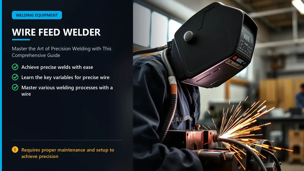
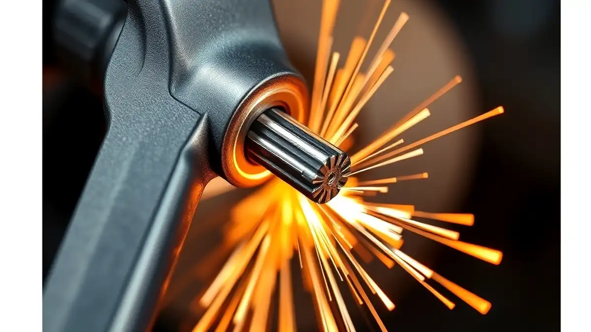
Every arc welding process needs four things: a heat source, a filler metal, shielding, and someone or something to move the heat along the joint. Stick welding delivers all three through a coated rod you hold in your hand. TIG delivers heat and filler separately, with you feeding rod while your other hand moves the torch. Wire feed welding collapses the whole operation into one element: a continuous wire that is both the electrode and the filler, fed automatically, in a steady stream, through a gun.
That single design decision is why wire feed welding is easier to learn than stick or TIG. Your hands do not have to coordinate feeding filler rod because the machine does that chore. You are left with aiming, moving at a steady speed, and managing a handful of settings. The trade-off is that you are trusting a mechanical system — rollers, liner, contact tip — to behave perfectly, and when it does not, the weld knows it.
The wire is electrical as well as mechanical. Current flows from the machine’s power source, through the gun, into the wire at the contact tip, and jumps across the gap to the workpiece as the arc. The wire melts off as it crosses the arc and deposits into the molten puddle. The rate at which it melts depends on how much current flows, so there is a direct relationship between the machine settings and how much metal lands in the joint per second. Once you see the machine as a system — feed it this, heat it that, set the stickout, move at this speed — the process stops being mysterious.
For an even broader grounding, our MIG welder basics for beginners guide walks the very first steps, and if you are weighing whether stick or wire feed is the right first process, the stick versus MIG discussion lays out the trade-offs honestly.
Before you can tune a machine, you need to know what every part is doing. The good news is that the parts list is short, and every wire feed welder, from a $150 garage special to a $5,000 pro rig, is the same five systems wearing different clothes.
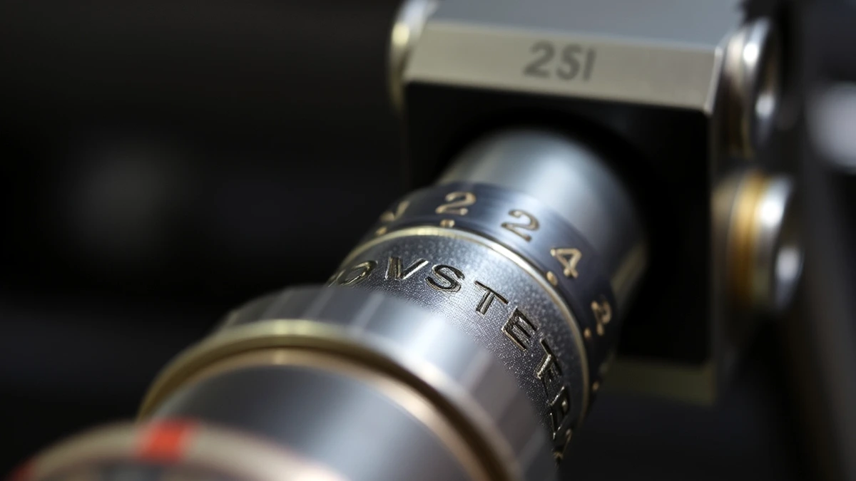
The gun carries current, wire, and gas to the joint. Inside it runs a liner — a flexible tube, steel or nylon — that guides the wire friction-free from the feeder to the contact tip. Liner size must match wire diameter; a 0.035 liner will fight 0.030 wire and catch it. The contact tip, a small copper piece threaded into the neck, is where live current transfers to the wire. It wears like a brake pad. A wallowed-out tip means intermittent arc contact, and that shows up as sputter and an inconsistent bead.
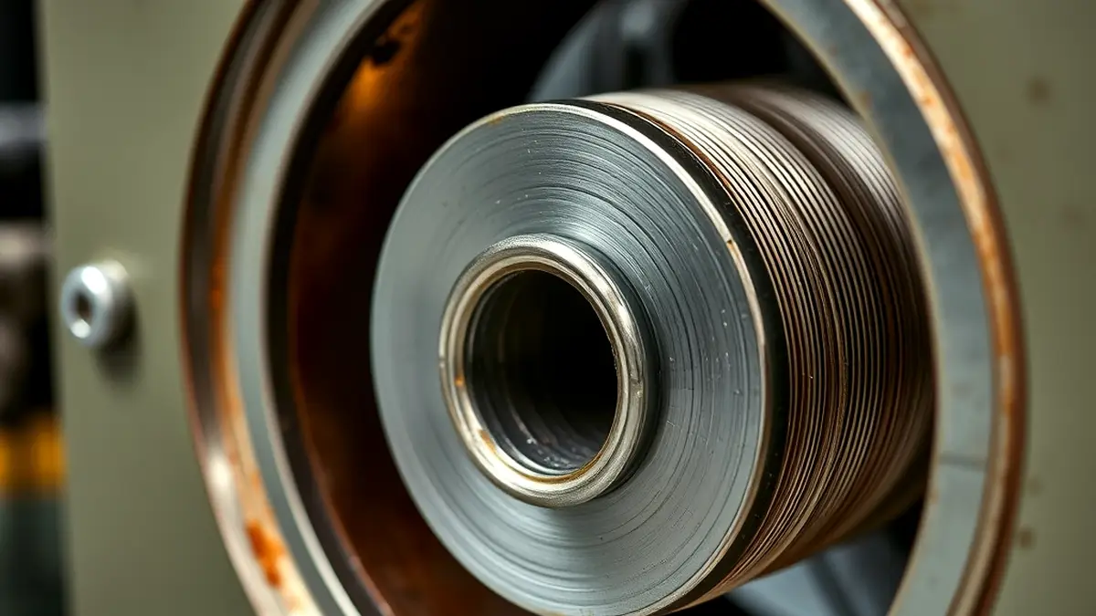
The feeder consists of a motor that turns a set of rollers, a drive system that pinches the wire and pushes it down the liner, and a tension adjustment. Most machines use two rolls; industrial machines often run four. The rolls must match the wire type — V-groove for solid wire, V-knurled for flux core, specific grooves for aluminum — and the tension has to be set so the rolls pull steadily without crushing the wire. A clearly scraped spot or ribs embossed into the wire means the tension is too high.
The power source converts wall current into regulated welding output. Wire feed machines are constant voltage (CV) machines: voltage stays roughly fixed while the wire feed speed determines current. This is the opposite of stick and TIG machines, which run constant current and let you control heat with your rod movement. Understanding that difference explains why settings behave the way they do — the voltage dial controls arc length and character, the wire speed dial controls amperage and deposition.
For MIG and gas-shielded processes, a solenoid valve opens when you pull the trigger and routes shielding gas from a cylinder through the gun to the nozzle. Regulator settings in the 20 to 35 cubic feet per hour range suit most work. The gas blanket keeps oxygen and nitrogen out of the puddle; without it, the weld porosity and oxidizes while you watch. For flux core in self-shielded mode, the gas system sits idle.
Every machine gives you at least two primary dials — one for wire feed speed (or amperage tap) and one for voltage range — plus polarity settings inside a panel or via a switch. Multi-process machines add a process selector, and higher-end units add pre-set synergic programs that let you pick metal and thickness and have the machine compute a starting recipe. Know where every control lives on your own machine before you worry about technique; fiddling when you should be welding is how you lose the rhythm of a joint.
| System | Function | Precision Killer When Neglected |
|---|---|---|
| Gun and liner | Delivers wire, gas, current | Dirty or kinked liner jams the feed |
| Drive rolls | Pinch and push the wire | Wrong rolls or tension burn the wire |
| Power source | Regulates voltage and current | Wrong process/polarity setting ruins the arc |
| Gas system | Shields the puddle | Low flow or leaks cause porosity |
| Contact tip | Transfers current to wire | Worn tip sputters and wanders |
| Ground clamp | Completes the circuit | Poor ground makes the arc unstable |
Quick Note: The liner is the most ignored part on hobby machines. A clogged liner produces feed problems that get blamed on everything else — wire, machine, wall power. Blowing the liner out with compressed air after every few hours of welding is a two-minute habit that prevents the entire class of “weird feed” complaints. If you are dealing with feed issues right now, our wire feed motor troubleshooting guide is a good place to start.
One of the pleasant surprises of modern equipment is that a single wire feed welder can run several processes. Understanding them lets you choose the right one for the job instead of welding everything with your default setting.
Short-circuit MIG is the standard wire feed process: solid wire, external gas, electrode positive, and a transfer mode where the wire shorts against the puddle many times per second. It is clean, cool enough for thin steel, and the easiest process to learn. Its weakness is wind — gas must protect the puddle — and marginal penetration on thick, dirty, or heavily scaled material. For clean indoor fabrication and thin sheet, it is hard to beat.
Flux core swaps the solid wire for a tubular wire packed with flux. In self-shielded mode no gas is needed, so it thrives outdoors and on steel that would pore up a solid-wire weld. It runs hotter, penetrates deeper, spatters more, and leaves slag to chip. For structural work in the open air, flux core often beats MIG outright. The differences are detailed in our flux core versus MIG comparison.
Many machines now switch between MIG, flux core, and even stick or TIG-lift modes with a dial and a lead change. Some add a spool gun port for aluminum. A well-chosen multi-process machine covers 90 percent of hobby and light commercial work from one box, which is why models like the ones in our best MIG welder for beginners and under-500 reviews are so popular. The catch is that switching processes properly means switching polarity, wire, gas, and often the liner — a job people skip, producing garbage welds that they blame on the machine.
Short Note: “Wire feed welder” and “MIG welder” are not always the same thing. MIG strictly means metal inert gas welding with solid wire and gas. A flux core machine is still a wire feed welder, just running a different electrode. When someone asks “can it MIG?” they usually mean “does it run sold wire with gas?” — that is the question to answer before buying.
Precision sounds like a marketing word, but in wire feed welding it has a concrete definition: controlling the inputs that decide where heat and metal go. A weld is precise when the bead width, height, and fusion are consistent across the joint, the toes tie in cleanly with no undercut, and the weld metal lands exactly where the joint needs it. Achieve that and the weld is strong; miss it and you have a bead that might hold or might not, and nobody knows until it is loaded.
Five variables sit under your control, and precision is the discipline of managing them simultaneously:
The trick is that the variables interact. Nudge the voltage and you may want to nudge the wire speed to match. Speed up your travel and the bead flattens, so you compensate with settings. Experienced welders juggle this constantly without thinking, which is why they can run beautiful beads on machinery they have never touched. They are not “naturally talented”; they have a mental model of cause and effect. Building that model is the real goal when you practice.
Pro Tip: Practice one variable at a time on a flat plate. Spend fifteen minutes changing only voltage, in half-volt steps, and writing down what each bead looks like. Then fifteen minutes on wire speed. Then travel speed. You will internalize the relationships three times faster than randomly adjusting everything.
Most ugly welds never had a chance because the setup was wrong before the arc struck. Run through this checklist every time you change wire, gas, or material — it takes five minutes and eliminates the majority of variables that wreck beads.
Solid wire comes in common diameters — 0.023, 0.030, and 0.035 inches — plus 0.045 and larger for industrial work. Thin sheet wants 0.023 or 0.030; most automotive and general fabrication runs 0.030 or 0.035 on shop machines. Wire diameter and metal thickness guides are in our MIG wire size chart. Cheap wire is a precision killer: inconsistent diameter and laminated, oxidized surface feed poorly and weld erratically. Buy from a brand you can trust; our best MIG wire recommendations will save you dead spools.
For mild steel, the common mix is 75 percent argon and 25 percent carbon dioxide (C25), or 100 percent CO2 for budget setups. C25 gives a smoother arc and less spatter; CO2 digs deeper and costs less but splatters more. Flow should be set in the 20 to 35 CFH range. Too little gas and you draw air into the puddle; too much and you create turbulence that does the same thing. If you are dialing this in for the first time, our MIG gas setting guide gives exact values. And argon alone is wrong for steel — pure argon is for aluminum and TIG, which is covered in the 100 percent argon question.
Install the correct groove for your wire, set the pressure so the rolls drive without slipping, and confirm the wire seats in the groove dead-on. A wire that lifts out of the groove causes eccentricity — the wire loops or bird-nests at the tip. Roughly a quarter to half a turn past snug is a good tension starting point for most roll setups.
Solid wire MIG runs electrode positive — the gun lead is the positive terminal. Self-shielded flux core reverses to electrode negative. Getting this backwards is the single most common setup disaster, and it produces symptoms that mimic every other problem. A polarity check belongs on every jobsite checklist. On the ground side, clamp to clean bare metal as close to the joint as practical, and check that the clamp’s spring still bites. A poor ground creates an unstable arc worst to diagnose because the machine reads normal.
Stickout is the distance from the contact tip to the workpiece. MIG likes roughly 3/8 to 1/2 inch; self-shielded flux core wants 3/4 to 1 inch. Consistency beats everything: if you vary stickout while traveling, the current changes and the bead width changes with it. Rest the nozzle in a steady position and keep it there.
Quick Note: Trim every new wire with a flush diagonal cut before threading it through the liner. A bent or burred tip will hang on liner joints and seat against the drive rolls incorrectly, and you will spend an hour diagnosing a feed problem caused by a bad snip.
If you understand only two settings on a wire feed machine, make it these two. Voltage and wire feed speed are locked in a partnership, and the ratio between them shapes every bead you will ever run.
Voltage controls the arc’s character. Think of it as the “heat on the wire” dial. At the correct voltage, the arc holds a steady, businesslike crackle and the puddle wets out smoothly. Voltage too low produces a short, sputtering arc with the wire stubbing and popping — spatter everywhere, poor fusion at the toes. Voltage too high stretches the arc into a long, searching flame that widens the bead, burns the edges, and deposits a thin, washed-out weld.
Wire feed speed controls amperage and deposition. Push more wire and more current flows; the workpiece receives more heat and more filler. On thick steel, this is how you lay down deep fill quickly. On thin sheet, it is how you blow holes. The two dials balance each other: a big jump in wire feed speed usually asks for a small bump in voltage to keep the arc comfortable, and on most machines the two are designed to be moved together along a curve, not independently.
| Material Thickness | Wire | Gas | Voltage | Wire Feed Speed |
|---|---|---|---|---|
| 24–22 gauge sheet | 0.023 | C25 | 14–16 V | 150–200 ipm |
| 16 gauge (1/16 in) | 0.030 | C25 | 16–17 V | 200–250 ipm |
| 1/8 in | 0.030 | C25 | 17–19 V | 260–320 ipm |
| 3/16 in | 0.035 | C25 | 19–21 V | 300–360 ipm |
| 1/4 in | 0.035 | C25 | 21–23 V | 340–420 ipm |
These are starting points, not gospel — machines vary, wire brand varies, position changes the numbers. Use the table to get close, then refine with the sound test: a correct MIG arc hisses and crackles like frying bacon in a steady rhythm. An arc that pops and stutters is starved for voltage or overfed on wire. An arc that roars and whistles is running too hot. Listen before you look; the welder’s ear is a legitimate instrument. A fuller set of reference values is available in our MIG wire speed and voltage chart.
Quick Note: Many entry machines hide these settings under taps or a single dial labeled “thickness.” That is fine — you are still controlling the same two variables, just coarsely. If you cannot fine-tune voltage, pick the tap closest to the material thickness and compensate with wire speed and travel.
Good settings are the foundation, but your hand is the figurehead. The gun angle and the way you travel dictate bead shape, penetration, and consistency, and these are the first skills to build once the machine is dialed in.
Hold the gun roughly perpendicular to the workpiece for direct bead placement, then tilt it 10 to 15 degrees. The tilt direction matters hugely. A push angle (gun tilted forward, in the direction of travel) produces a flatter, wider, shallower bead with less penetration — ideal for thin steel and for seeing the puddle clearly. A drag angle (gun tilted back, pointing at the weld you just made) concentrates heat at the leading edge for deeper penetration, and it is the standard for flux core and structural work. For solid MIG on clean shop steel, a slight push gives the cleanest cosmetics. The full reasoning behind these choices is explained in our push versus pull technique piece, which applies to more than flux core.
Travel speed is the rhythm of the whole operation. Too fast: the bead sits thin, width shrinks, toes undercut, and penetration suffers because the arc barely lingers. Too slow: the puddle overheats, the bead humps up, and on thin metal it blows right through. The correct speed keeps the puddle about the width you want, with the bead reinforcement standing just proud of the plate. Watch the molten pool, not your wire or your wishful thinking, and let it set your pace.
Narrow beads under half an inch are best as stringers — straight line, no weave, maximum control. Wider joints and most vertical work want a weave to spread heat and metal evenly. The two classic patterns: a slow C or letter “j” for filling a joint face, and a figure-eight for wider gaps. On vertical-up, a straight weave across the joint face is the standard, letting you pause at each edge for the puddle to tie in. Whatever pattern you choose, keep the same one for the entire pass — a bead made of three different patterns looks amateur and fusions unpredictably at the transitions.
Pro Tip: Run a straight stringer at a comfortable speed on clean flat plate. Then run the same settings a quarter speed faster and a quarter slower. Compare the three beads. In ten minutes you will have visually mapped travel speed for that machine, and that map transfers to every job after it.
Flat and horizontal are where beginners live, but real projects demand positions that fight gravity. Wire feed welding is better suited to position work than most people expect once the techniques are known.
Flat is the easiest environment: gravity holds the puddle. Push the gun slightly, string or weave, keep the puddle tight. Horizontal fillet welds — the classic T-joint with the plate lying flat — want the gun angled so the arc hits both legs of the joint equally, about 45 degrees in the gap between the two plates. Watch the top leg especially; molten metal wants to sag down toward the bottom leg and leave the upper toe starved.
Vertical-up is the strong choice for structural welds: you start at the bottom and climb, letting each level of solidified weld support the molten puddle above it. The penalty is speed — climbing is roughly half the deposition of flat welding — and travel needs the weave plus a slight pause at each edge so the puddle can freeze before you move up. Gravity is your friend here if you respect it.
Downhill welding is fast and produces a shallow, smooth bead that suits thin sheet where penetration must be limited. On thick steel it is considered unsafe because the fast travel starves the joint of proper fill. Form the habit of asking “will this be climbed or descended?” for each job, and match the technique to the code instead of the easier option.
Overhead is the discipline test: the puddle hangs below you and asks to fall. The fixes are all conservative — drop the heat slightly, keep the puddle small, keep a short arc and a slight push angle, and move at a steady, deliberate pace. Stop, look, restart cleanly is acceptable and common; the failures come from rushing a puddle that has already overheated. Overhead work burns more wire for less deposited metal, but the joints hold fully if you let them.
Short Note: Position changes your settings more than people guess. Vertical and overhead want roughly 10 to 15 percent less heat than the flat settings for the same steel. Lower the voltage, lower the wire speed, and let travel speed pick up the difference — the puddle will tell you if you fought it.
A wire feed welder will happily try to weld almost any metal a hobbyist brings home, but “try” and “weld properly” are different verbs. Each material changes what the machine is doing, and the adjustments follow predictable rules.
Mild steel is the home turf. C25 gas, ER70S-6 wire, polarities and speeds from the charts above, and a clean surface produce reliable, inspectable welds. The main variable is cleanliness — mill scale, paint, oil, and rust all invite porosity. A flap-disc or wire-brush pass an inch past the joint edges is cheap insurance. With spool quality wire and a clean surface, a 0.030 wire on 1/8-inch plate is the sweet spot for most beginners.
Stainless wants its own gas and wire: run 90/10 argon/helium or 98/2 argon/CO2 mixes with a stainless wire like ER308L. The big precision concern is heat. Stainless soaks and retains heat, so long beads tend to overheat and lose corrosion resistance. Keep beads short, let the metal cool between sections, and use a slightly lower heat than you would for steel of the same gauge. Backward planning and short welds are the whole game here.
Aluminum is where wire feed welding gets humble. It conducts heat away so fast that a standard bench welder cannot keep up with 0.035 aluminum wire in a push-pull gun, and even then aluminum requires spools of softer wire, big drive tensions, and special liners. For hobby machines, the practical path is a spool gun — a separate gun that houses its own spool and feeds short distances, letting aluminum wire reach the arc without kinking in the liner. It works on machines with spool gun capability, and it genuinely unlocks sheet aluminum. The trade-offs are documented in can a MIG welder do aluminum and the spool gun discussion in this cast aluminum piece. If aluminum is a regular job, TIG remains the precision king — see our comparison of MIG versus TIG before you commit.
Thin metal punishes everything: heat blows through, warps panels, and starts the bead burning wider as the puddle softens under it. The rules: smallest wire you can feed (0.023 or 0.030), low voltage, short beads — often an inch or two long with cooling pauses — and a stitch pattern that alternates sides on long seams to share the heat. A brass clamp or a spot-cooling rag behind the weld steadies the temperature. For the full strategy on sheet metal, read welding thin metal like a professional.
Pro Tip: Feed the same thickness of test coupon before touching a precious panel. Thin metal rewards knowing your machine’s cold endpoint — the lowest usable settings — and the only way to commit those to memory is burning a few coupons learning where it starts blowing through.
Wire feed machines wear, and most precision problems trace to consumables before they trace to technique. Work through this table when a bead stops behaving.
| Symptom | Likely Cause | Fix |
|---|---|---|
| Birdsnest of wire at the tip | Kinked liner, tight spool brake, wrong rolls, burred wire end | Straighten gun, free the spool, trim wire squarely, clean liner |
| Sputtering, rough arc | Worn contact tip, dirty liner, wrong polarity | Swap the tip, blow out liner, check polarity |
| Porosity that repeats | Gas flow off, leaks, contaminated steel, no gas | Check flow, soap-test the hose, clean the joint |
| Heavy spatter | Voltage too low for wire speed | Raise voltage slightly, tighten stickout |
| Concave underfilled bead | Travel too fast or voltage too high | Slow down, drop voltage a touch |
| Burn-through on edges | Too much heat for the metal | Drop wire speed and voltage, stitch instead |
| Wire snarls around drive rolls | Tension too tight or wire pinched | Loosen tension to the first steady feed point |
| Arc wanders side to side | Worn tip orifice, wind on gas-shielded | Replace tip, guard against draft |
Two of these deserve extra mention because they fool people for weeks. The first is the worn contact tip: an elongated, oval tip bore makes the arc flick and wander, and the symptom looks like a technique problem. When in doubt, swap the tip. The second is gas flow — a kinked hose or a regulator drifting on a low cylinder causes intermittent porosity that comes and goes, which gets blamed on the wire or the steel. Check the easiest consumables first, always. For feed-specific faults like a motor that spins but will not push wire, our wire feed motor deep-dive and the motor troubleshooting guide walk through mechanical fixes step by step.
Quick Note: Keep a small kit of spares on your bench: two contact tips, a liner, a spare set of drive rolls, and a regulator washer. Most wire feed emergencies consume one part and ten minutes. Lacking the part turns a ten-minute fix into a visit to the store and a day of lost shop time.
Wire feed welding punishes lazy preparation faster than any arc process, because the shielding gas protects only the molten metal — contamination in the joint line travels straight into the puddle. Porosity, the pinhole condition that weakens a weld and embarrasses its author, is almost always contamination in one form or another.
The rule of thumb professional fabricators use: clean the joint an inch on each side, into bare bright metal, before welding steel. Oil and any residue — even invisible machine oil — should be wiped away with degreaser. Mill scale can be tolerated only on a limited basis; better to grind it. Galvanized steel deserves a dedicated paragraph, because welding it can produce serious fume hazard and the coating melts before the steel. The zinc coating must be ground back from the joint, ventilation provided, and a respirator worn. Our full piece on MIG welding galvanized steel is required reading before your first workpiece of it.
Precision extends to not contaminating the machine itself. Spatter buildup on the nozzle steals gas flow and distorts shielding; wire flame-coats the liner with copper dust; and moisture in a cheap spool shows up as porosity three weeks later. Anti-spatter gel or a light spray on the nozzle before work gives you clean flow and makes slag discharge easy.
Short Note: Nozzle condition is stealth precision. A nozzle caked with spatter closes off the gas stream and pulls in air around the sides, producing porosity that looks like it came from bad gas. Dip the nozzle in anti-spatter before each session and wire-brush it after. It takes seconds and it silently govern arc quality.
Beginners treat shielding gas as an afterthought because it is invisible, but the gas is doing a full-time job that directly decides whether your beads are clean or full of porosity. The shielding blanket must sit over the puddle from the moment the arc starts until the weld solidifies. Any gap in that blanket is where atmospheric oxygen and nitrogen rush in and poison the weld metal.
The two options for mild steel are the 75/25 argon/CO2 mix (C25) and 100 percent carbon dioxide. C25 is the smoother performer: lower spatter, a more stable arc, less clean-up, and better bead cosmetics. CO2 runs hotter and drives deeper penetration, and it costs substantially less per fill, so budget-conscious shops and heavy outdoor work choose it despite the extra spatter and messier arc. Both are correct answers; the choice is a trade between finish quality and operating cost. If you want the machine to run every day without fussing, C25 is the hood default. If you are burning through wire on heavy structural work and want maximum penetration per dollar, CO2 earns its place.
Aluminum and stainless are a separate story. Aluminum runs on pure argon, sometimes with helium blended in for thicker sections so the arc carries enough heat into metal that conducts it away almost insultingly fast. Stainless prefers argon with a small CO2 addition — anywhere from 2 to 9 percent depending on the wire classification — to stabilize the arc without overdosing carbon that would weaken corrosion resistance. Getting the mix wrong produces wrong results in minutes: an argon-only steel weld looks like wire spat on a cold plate, and a CO2-heavy stainless job ends up dark and oxide-riddled.
Flow rate matters as much as content. Set the regulator in the 20 to 35 cubic feet per hour range and re-check it as the cylinder empties, because a cylinder with low pressure stops delivering usable flow no matter what the flowmeter claims. Two classic mistakes hurt more welders than the choice of gas itself: setting the flow, then letting a kinked hose behind the table kill it before the first bead; and letting a drafty bay or a passing fan stir the shield mid-weld. Make flow and wind checks part of the routine and you will never pour over an invisible problem.
Manufacturers publish excellent gas and process references if you want the deeper layer. Lincoln Electric and ESAB both maintain free process libraries that spell out gas recommendations, wire classifications, and setting tables for every common material. Between those resources and our own MIG gas setting guide, you can build a solid gas plan for any job before the cylinder valve is even opened.
Quick Note: Test your gas connections the way you check a bicycle tube: mix a little dish soap with water, brush it over the hose joints and regulator fittings while the gas is flowing, and watch for bubbles. A pinhole leak above the regulator causes exactly the intermittent porosity that usually gets blamed on a cheap spool of wire.
Buying a wire feed welder is a series of honest questions about what you will actually do with it. The machine that looks impressive in a catalog can be the wrong machine for your garage, and vice versa. Walk through these factors before you compare price tags.
Machines run on 120V or 240V. A 120V machine plugs into any wall outlet and welds steel up to roughly 3/16 inch in a single pass — genuinely useful for exhaust work, panels, gates, and repairs. A 240V machine needs a proper circuit and welds thicker steel, runs longer duty cycles, and opens up bigger structural jobs. If you only have a 120V outlet, a capable 120V machine is the right answer, not a stalled start on a 240V rig you cannot feed. For the power supply side of the discussion, our welder outlet guide is the reference.
Duty cycle is the percentage of a ten-minute window you can weld continuously at a rated amperage without the machine overheating and shutting down. A 20 percent duty cycle at 150 amps means three minutes of welding per ten — fine for hobby work with natural breaks, restrictive for hour-long production. The bigger the job, the more you value duty cycle. For a light fabrication shop doing repair work all day, a machine with a 60 percent figure at your working amperage is the one to trust. We have a deep-dive on improving duty cycle if yours runs hot.
Amperage range is the machine’s engine size. Compare it to your material: tools that weld 20 gauge to 3/8 inch cover almost every welding task a fabricator meets, and a 250-amp range covers nearly all of it. Machines at the low end are oversold — a 90-amp box that claims 1/4 inch single-pass capability is lying. Read the fine print, and read our best 110V MIG welder recommendations for realistic capability.
Some features earn their price every time: a smooth, adjustable wire feed; good spool gun support if aluminum is on your horizon; a sensible ground clamp; a gas solenoid; and a user-adjustable voltage tap count (more taps means finer control). Fancy synergic programs are convenient but not a substitute for understanding the dials. Auto-set settings get you in the neighborhood — you still have to refine with the sound test and your eyes.
| Scenario | Recommended Direction |
|---|---|
| Occasional auto and light repair | 120V, 0.023–0.030 wire, C25 ready |
| Trailers, gates, structural hobby work | 240V 180–200 amp, 0.030–0.035 wire |
| Outdoor/field repair, rusty stock | Flux core capable, electrode negative supported |
| Heavy fabrication, daily professional use | 250 amp, high duty cycle, dual-process |
| Aluminum as a regular task | Machine with spool gun port and 240V |
Quick Note: Buy more amperage than you think you need within your power budget. Welding at the top of a machine’s range maxes out its duty cycle, and a machine run at 80 percent capacity all day ages faster and welds more erratically than one loafing at 60 percent. Overhead is reliability.
A wire feed welder rewards maintenance out of proportion to the effort, because its precision depends on mechanical accuracy in the feed system. Ten minutes of care saves hours of troubleshooting. Build these into a rhythm.
After every session, blow the liner out with compressed air from the feeder end. Wipe the drive rolls free of the brass dust that solid wire leaves behind. Replace the contact tip when the bore walls out, and inspect the liner for kinks whenever the gun cable is re-routed. Trim wire ends flush each time you re-thread.
Consumables have a service life whether you want to admit it or not. Contact tips do not last forever, nor do liners or drive roll sets. The price of each is trivial next to the hour of diagnosing a bad one. Keep spares on the shelf, and swap them on a schedule instead of waiting for failure.
Every few months, verify the basics: that the wire feed speed dial roughly matches the actual feed rate, that the voltage taps hold correct values, and that the gas solenoid opens fully when the trigger pulls. Check the ground clamp bite and lug tightness. Machines drift, and a badly drifted machine will teach you bad habits because the settings no longer mean what they say. A catch can: count inches fed in 15 seconds against the dial’s inches-per-minute scale, and you will know if the display is lying.
Pro Tip: Make maintenance its own small ritual before the week’s first weld: new tip if in doubt, liner blow-out, spatter clean of the nozzle, gas check. It is a sixty-second warm-up, and it guarantees every weld you run that day starts from a true machine.
Every welder makes the same mistakes on the way in; the trick is recognizing them early and then doing the harder thing — unlearning them. Here are the ones I see most on job sites and in garages, roughly in the order they strike.
The pattern behind all of these is the same: a search for a single cause when welding is a system of linked causes. Settings, setup, consumables, technique, material, and environment all interact. Precision comes from diagnosing honestly — checking the simple, cheap things first and letting the evidence, not the ego, name the culprit. When in doubt, run a clean test bead on known-good stock and let that bead talk.
Important: The most expensive mistake is copying settings from a machine that is not yours. Voltage-tap scales differ wildly between brands, wire feed displays lie on some units, and identical dial positions on two machines can produce completely different arcs. Your settings live on your machine, proven on your test plates.
Precision and safety are not separate topics. A welder who is flinching, or welding in a haze of fume, or worried about fire burning behind a shelf, cannot hold a steady travel speed. Safety is a prerequisite for good welding, not a checkbox after it.
The minimum stack for wire feed welding: an auto-darkening helmet with the correct shade (a little higher than MIG’s usual range for flux core), safety glasses under the helmet, a fire-resistant jacket or heavy long-sleeve cotton shirt, welding gloves with long cuffs, and sturdy leather boots. The arc radiates UV, spatter burns skin on contact, and flying hot metal pings around the booth — half measures collect scars. For the right gear for this process, see our MIG welding helmet and MIG gloves picks, plus the overall welding safety checklist.
Wire feed welding produces fume that nobody should breathe routinely. The metals being welded — and coatings on them — determine what is in it, from simple metal oxides to the chromium and nickel of stainless and the zinc oxide of galvanized metal. OSHA sets exposure limits for a reason; the governing standard is consolidated in OSHA’s welding, cutting, and brazing standard, and an accessible overview is on OSHA’s welding safety pages. NIOSH maintains health guidance for welders as well, collected at their welding resources. In practice: use local extraction or work outdoors where the breeze carries fume away, add a proper respirator — our respirator guide covers cartridge types — and never weld painted, oily, or galvanized stock without ventilation and protection.
Remove combustibles from ten or more feet around the work, keep a rated extinguisher within reach, and post a fire watch when working anywhere near materials that could smolder. Sparks travel; welds drip. Electrically, keep the work lead secure, inspect the gun cable for worn insulation, and make sure the machine is plugged into a properly grounded outlet on a circuit rated for its draw. The National Fire Protection Association publishes hot-work standards that define the fire-watch practices pros follow, and they apply to a garage just as much as a plant floor.
Important: When flux core and galvanized steel meet indoors, run the fume camera of your judgment: this is the single most common cause of metal fume fever in hobby welding, and it is fully preventable with grinding, ventilation, and a respirator.
These are the questions that come up in nearly every conversation about wire feed welders, whether from a first-time buyer or a welder who has been at it a while.
Joining steel and steel alloys with a continuous wire electrode. Practically, that covers fabrication, auto repair, trailers, gates, structural work, repair of farm and shop equipment, and light stainless jobs. With a spool gun, aluminum is reachable too. It is the most popular process among hobbyists for good reason.
A motor pushes wire from a spool through a liner to a contact tip, where electric current jumps from the tip to the workpiece as an arc. The wire melts into the joint as filler, shielding gas protects the puddle in MIG mode, and you guide the gun along the joint. Voltage and wire feed speed set the arc character and the amount of metal deposited.
Yes, into its own class. A correctly made MIG weld with ER70S-6 wire delivers tensile strength comparable to stick welding of the same material. Strength depends on fusion, penetration, and cleanliness — not on the process label. The subject gets its own treatment in is MIG welding strong, because it deserves a full answer.
No, and the machine does the hard part by feeding the wire. The beginner’s curve is about settings and a steady hand rather than coordination. The honest version is in is MIG welding hard; the short answer is that the first spool of wire will produce decent welds with a little instruction, and precision takes practice — not talent.
MIG uses solid wire plus external shielding gas; flux core uses tubular wire with internal flux. Self-shielded flux core needs no bottle and welds outdoors and on dirtier steel, but spatters and slags more. MIG runs cleaner indoors and needs a quiet environment. Both run through the same machine with the right polarity swap.
For general fabrication and repair, a wire feed welder. For precision and thin or non-ferrous work, TIG. Many welders want both eventually, so the honest advice is start with MIG or multi-process, get competent, then add TIG when the work calls for it. Our comparison of MIG, TIG, and stick helps you make the call for your own projects.
Yes, with small wire and disciplined heat. Use 0.023 or 0.030 wire, low voltage, stitch welds, and cooling pauses. On very thin body panel stock, practice on scrap first — the same advice that applies across all processes, laid out in this thin metal guide.
Nobody gets precise by wanting it. A short, structured practice loop beats three-hour binges that end in frustration, because the loop forces you to change one thing at a time and observe the result. Run this as a thirty-minute session, three times a week, for your first month, and you will have a foundation that most hobbyists never build.
Week one is about sound and flat beads. Set up clean 1/8-inch plate, dial in C25 and 0.030 wire, and run stringer beads at a comfortable travel. Ignore perfection; chase a steady sizzle and a consistent bead width. Say the checklist out loud before every pass: “Same stickout, same angle, same speed.” That verbal cue quietly builds the discipline of checking your hand instead of only watching the puddle.
Week two is about the two dials. Run the same plate and hold travel constant while you change only the wire feed speed in small steps — three beads at three speeds. Then hold wire speed constant and change only the voltage. Photograph or sketch each bead, note the settings on tape, and stick the tape inside the machine door. You are now mapping your machine, and that map is worth more than any internet chart because it is measured on your rig with your wire.
Week three is position work. Take the flat skills to horizontal fillets by welding a T-joint on the bench. Watch the toes on both legs of the joint, not just the one facing you. Then set the same T-joint vertical and practice the climb: weave, pause at edges, step up. Wash, repeat, and let each pass teach you how much puddle it takes before it sags.
Week four is materials and habits. Weld short coupons of thin sheet at the lowest usable settings, test your machine’s cold endpoint, and finish the month with a stainless or aluminum coupon if your machine supports it. Throughout, keep the maintenance ritual alive: blow the liner each session, swap tips when in doubt, and store the wire dry. Clean tools and clean habits are the part of precision that no welding video shouting at you from a phone will ever mention.
Short Note: Keep a small notebook dedicated to practice. One line per bead: settings, material, position, and what you saw. After thirty sessions you will have a personal database of cause and effect that makes every future setup a matter of memory instead of guessing.
Wire feed welding rewards the welder who treats the machine as a system instead of a black box. Learn the anatomy, respect the pairing of voltage and wire speed, keep the feed path clean, and let every bead teach you one thing. That is the entire secret behind welders who make precision look effortless — they are not gifted, they are systematic.
Start on flat plate with a proper setup and a dialed arc. Run stringers until the bead width is steady. Then take the technique on the road: horizontal joints, vertical-up, overhead, stainless, aluminum if the machine will support it. Every position and material you master makes the next one easier, because the skills — consistent stickout, steady travel, clean prep, honest settings — transfer wholesale.
And when a weld misbehaves, resist the urge to blame the machine. Work the checklist: tip, liner, gas, polarity, ground, settings, material prep. Nine times out of ten the fix is a consumable or a habit, not the equipment. Precision is earned in those ten-minute checks, one clean bead at a time.