MIG Basics: The Complete Beginner’s Guide to MIG Welding (Setup, Settings & Technique)
Learn MIG basics from scratch: how GMAW works, machine setup, wire and gas choices, transfer modes, technique, troubleshooting…
READ ARTICLE →# Can I Weld Aluminum With a MIG Welder? Expert Tips Revealed!
Last updated: October 2026
A hobbyist with a 140-amp MIG welder, a spool of ER4043, and a Facebook Marketplace aluminum trailer to repair asked the question that starts half of all aluminum stories: can I actually do this with the machine I already own? He had welded steel for two years, assumed gas was gas, fed soft aluminum wire through a liner built for stiff steel, and produced a bead that looked like chewed foil — porous, wandering, half-stuck. The machine wasn’t the problem. The setup assumed steel at every stage — liner, gas, technique, settings — and aluminum refuses to be welded like steel.
So — can you weld aluminum with a MIG welder?
Yes — MIG welding aluminum (GMAW) is a legitimate, common, production-grade process — it’s how aluminum trailers, dump bodies, marine fabrications, and factory frames get joined every day. But it is not “swap the wire and go.” Aluminum through a MIG system demands the right gun feeding system (spool gun or push-pull — a standard steel liner will birdnest soft wire), 100% argon shielding gas (never CO₂ mixes), clean aluminum-specific wire (4043 or 5356, stored dry), dedicated cleaning discipline (oxide and oil are the enemy), aluminum technique (push, not pull — the opposite of steel), and settings matched to transfer mode and material thickness. Get those six right and your machine welds aluminum beautifully; skip any one and you’ll chase porosity, feeding failures, and beads that look the part while holding nothing.
This guide delivers the complete system: why aluminum behaves differently through a MIG gun (thermal and wire-feeding physics); the gun decision (spool gun vs push-pull vs modified standard gun — with a buying framework); gas selection and flow (100% argon, why the 75/25 myth persists, hose and flow discipline); wire selection (4043 vs 5356, diameters, cleaning and storage); machine settings and transfer modes (spray, pulse, short-circuit — and the DC polarity reality); prep that makes or breaks the bead (cleaning, brushing, bevel, fit-up); the aluminum technique manual (push angle, stickout, travel speed, weave limits); every common defect decoded (porosity, lack of fusion, burn-through, worm tracking, birdnesting — with fixes); thin-gauge and 110V reality; when to choose TIG instead; safety (fumes, eye, gloves); then myths, scenarios, FAQs, and the verdict.
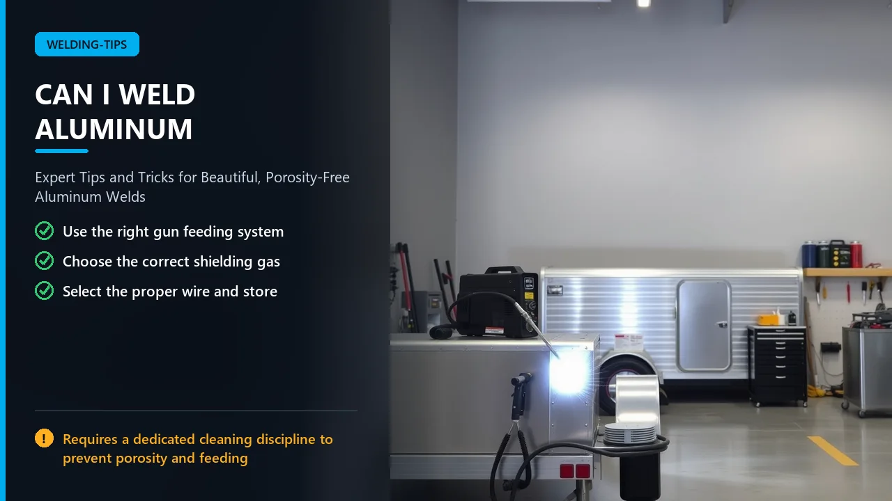
The full verdict in seven points:
The one-sentence verdict: your MIG welder can weld aluminum — with an aluminum feeding system, pure argon, the right wire, obsessive cleaning, and push technique; treat it like steel and it will punish you for it.
Five physics facts drive every rule in this guide — understand them and the setup stops being arbitrary.
Aluminum’s protective oxide layer (Al₂O₃) forms instantly in air — and melts around 2,050°C, while aluminum itself melts at 660°C. The arc cannot “melt through” oxide the way it handles steel scale; oxide must be removed mechanically (brushing) and chemically (cleaning) before welding, or it floats into the pool as inclusions, disrupts wetting, and creates the lumpy, dirty bead that discourages beginners. This single fact explains the entire prep ritual.
Aluminum conducts heat roughly three to four times faster than steel. Heat you put into the joint races away from the arc into the surrounding mass — which means: higher current settings than intuition suggests (often comparable or higher than steel of the same thickness, not lower), faster travel (linger and you melt through; hesitate and the heat dissipates without joining), and preheat thinking for thick/heatsink sections (control the heat sink, don’t fight it). Beginners dial down out of fear and get cold, un-fused beads; the metal demands confident, hot, fast welds.
Aluminum MIG wire is soft — compared to steel wire’s stiffness, it buckles under pushing force anywhere friction exceeds its column strength. That’s why standard steel liners (with their tight bends and rough interiors) birdnest it, why cable length matters, and why gun systems dominate the aluminum conversation. The feeding problem isn’t the machine’s amperage — it’s the path.
Molten aluminum is runnier (surface tension roughly half of steel’s), oxidizes in the arc, and shows less color change as temperature rises — the puddle is bright and fluid with no color cues. Flow management comes from travel speed, angle, and arc sound rather than watching the pool glow. It wets widely on clean base and balls up on contaminated base — the puddle itself is a live cleanliness indicator.
Molten aluminum absorbs hydrogen readily and rejects it on solidification — blowing the gas porosity that riddles careless beads. Hydrogen sources: moisture in gas lines, damp or dirty wire, oil, paint, cleaning residue, humid storage. Dryness and cleanliness are anti-porosity engineering, not fussy habits.
Every section that follows traces back to these five facts: gun systems exist because of wire softness; pure argon exists because arc stability and oxide behavior demand it; push technique exists because of pool flow and cleaning action; cleaning exists because of the oxide and hydrogen stories. Learn the why and the how memorizes itself.
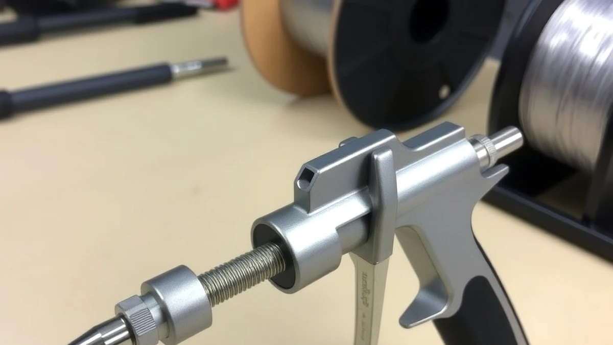
The feeding system is the make-or-break hardware choice — get it right and the rest is settings; get it wrong and no setting saves you.
A small spool (1–2 lb) mounted directly on the gun — the wire never travels through a long liner at all.
Drive motor at the machine (pushing) and a second motor in the gun (pulling) — tension stays near zero along the whole path.
A conventional gun with modifications: U-groove drive rolls (grip without crushing soft wire), a clean, sharp-bend-free liner (or Teflon/ultra-slick liner), short cable length, careful routing with wide-radius bends.
Non-negotiable regardless of option: U-groove (or V-groove only for aluminum-specific drives) rolls, clean liner, sealed wire storage, and tension set by the “push-until-it-stalls-then-back-off-one-turn” check rather than guesswork. Feeding problems blamed on the machine are almost always feeding-path problems.
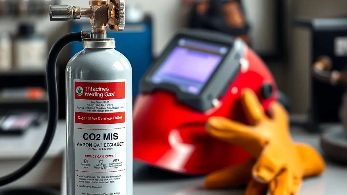
All aluminum MIG runs 100% argon. Not 75/25, not tri-mix, not helium blends (except specialized industrial exceptions you are not running). Argon’s inert, heavy blanket stabilizes the arc on aluminum, supports spray transfer, and — at proper flow — shields the pool from the atmosphere that would oxidize and contaminate it.
The 75/25 argon-CO₂ blend exists for steel: CO₂ adds penetration and arc energy at lower cost. On aluminum, CO₂ breaks down in the arc — carbon and oxygen interact with the molten metal, destabilizing the arc, spattering, increasing porosity and oxide inclusions, and generally producing beads that look angry and weld worse. This is the science behind can you weld aluminum with 75/25 — the answer is no, and now you know the why.
A standard 80–125 cu ft argon cylinder covers a lot of hobby aluminum; watch pressure-gauge levels, secure the cylinder upright, and treat regulator freezing (rapid drawdown) as a flow-planning signal, not a mystery. Pure-argon purity spec: industrial grade 99.996%+ — the cheapo unmarked tank from unknown supply chains is a porosity variable; buy from reputable gas suppliers.
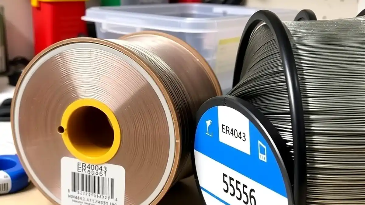
ER4043 (Al-Si ~5%):
ER5356 (Al-Mg ~5%):
Rule of thumb: unknown or cast or cosmetic → 4043. Marine, strength, 5xxx base, anodize match → 5356. Match wire family to base alloy whenever the spec exists — filler selection is a rod-size-and-class decision translated to wire.
Aluminum wire arrives clean and must stay clean:
GMAW on aluminum runs electrode positive (DCEP / reverse polarity) — standard for essentially all GMAW; your machine’s polarity setup for steel MIG carries over (where multi-process machines switch polarity, confirm it’s set for gas MIG). The cleaning arc action in DCEP also helps scrub the pool — one more reason not to experiment with EN on aluminum MIG.
1. Spray Transfer (The Thick-Material Workhorse)
2. Pulse MIG (The Thin-Gauge Savior)
3. Short-Circuit (The Cautious Thin Mode)
Every machine differs — but the philosophy: heat matched to thickness (hotter than steel intuition), wire speed matched to heat (balanced arc sound), and travel speed managing the input. Practical calibration method:
Balanced: arc hisses steadily, wire melts just at the tip (no balling ahead of arc, no stubbing). Wire too fast: stubbing, cold blobs, unfused centers. Wire too slow: erratic arc, wandering, burn-back risk. Voltage too high for speed: arc blow, spatter, undercut. Balance first, then fit to travel speed and bead width. Aluminum punishes imbalance faster than steel — the pool is less forgiving.
For aluminum MIG: push the gun — travel forward, gun angled back over the unwelded joint ahead… stated plainly: the gun points in the direction of travel (nozzle leading), pushing the pool backward under the arc. This is the opposite of the drag/pull used for steel verticals and many steel beads — and it matters because:
Exceptions and nuance: some positions (vertical-up, specific gap-filling) may modulate angle — but the default muscle memory for aluminum flat/horizontal MIG is push. If your instinct says drag because steel taught you to — override it.
Fast and even — the heat-sink reality means: too slow = melt-through, excessive width, heat distortion; too slow with insufficient current = a wide cold bead sitting on the surface. Too fast = lack of fusion, ropiness, skipping. Aim for the speed where the pool wets both toes evenly and the bead lays down at the specified width — practice runs on coupons set the rhythm better than any written number. The sound helps: steady hiss at constant pitch = steady conditions; wandering sound = wandering variables.
Settings knowledge only becomes skill through repetition — three drills build the whole technique foundation:
Run the drills when setting up a new wire/gun combination or after any feed-system change — re-calibration takes fifteen minutes and prevents the hour-long mystery hunt that follows an unlogged setup drift.
Looks like: pinholes, surface bubbles, subsurface cavities revealed on cut/etch; often clustered at starts or along the bead. Causes, ranked by likelihood:
Fix order: re-clean obsessively → verify gas (pure argon, 20–30 CFH, leak check, wind screen) → shorten stickout, confirm push → purge line, check nozzle → replace suspect wire with sealed spool. Repeat coupons until the bead is glassy.
Looks like: bead sitting on the surface with unfused edges; filler piled where base didn’t melt; deceptive visual “coverage” that fails under load. Causes: too little heat for thickness (fear settings), travel too fast, short-circuit mode on material that needs spray/pulse, oxide not removed (arc stalls on oxide), poor fit-up gaps bridged by filler alone. Fixes: raise heat (voltage + wire together), drop to slower confident travel, switch to spray/pulse for the thickness, re-prep the joint zone, tighten fit-up. Verification: cut and bend a coupon — the honest test; surface looks lie.
Looks like: holes, sagging, collapse mid-bead. Causes: too much heat, too slow, dwell at starts/stops, wrong mode (spray on too-thin stock), inadequate backing/heat sinking. Fixes: pulse if available; if short-circuit, keep it clean and tight-fit and accept its fusion limits; faster travel; copper backing/chill block; smaller diameter wire (.030″); lower settings with balance maintained; more tacks to control distortion. See thin and 110V.
Looks like: irregular surface tracks or embedded oxide films along/under the bead; dull, dirty appearance. Cause: oxide layer not removed (the arc rolled contaminated surface into the pool) — usually skipped brushing or brushing with a steel-contaminated brush. Fix: dedicated stainless brush, fresh strokes immediately before welding, solvent clean, remove any steel-brush contact zones.
Looks like: wire bunching at the drive rolls or entry; erratic arc; feeding pauses. Causes: wrong drive rolls (V-groove crushing aluminum instead of U-groove guiding), excessive tension, kinked/contaminated liner, wrong spool tension, worn liner, wire jumping the feed groove. Fixes: U-groove rolls → set tension by the stall test → replace liner → check spool brake/tension → route cable with wide bends → confirm wire diameter matches groove. Prevention is 90% of feeding.
Looks like: longitudinal or crater cracks; often at stops, restarts, or restraint-heavy joints. Causes: crater not filled (the classic stop-crack), heat-treatable base with 5356 in a high-restraint joint (filler mismatch), excessive restraint + fast cooling, contaminated pool. Fixes: proper crater technique (ramp-out/dwell), choose 4043 for crack-prone 6xxx repairs, reduce restraint via sequencing/preheat where procedures allow, clean everything.
Causes: poor ground (oxide-insulated clamp), contaminated tip, wrong stickout, gas disruption, mismatched settings, shared machine path (steel residue in liner). Fixes: clean, close ground → new contact tip (aluminum-friendly, correct bore) → stickout → gas → balance settings → dedicated liner.
Causes: excessive travel angle, speed too fast for current, heat biased to the steel… (in aluminum-only joints: heat/angle imbalance), improper work angle on T-joints. Fixes: soften angle, slow slightly, correct work angle to equalize toes, modest weave to tie the upper toe.
Three questions fix most aluminum MIG problems in order: 1) Is it clean? (wire, base, brush, gas) 2) Is it balanced? (voltage–wire speed–speed) 3) Is it fed? (gun path, rolls, stickout). Answer those before touching exotic variables.
Thin aluminum + high conductivity + fast heat travel = the material wants to melt away before the joint reaches fusion temperature. The classic beginner trap: dial down the heat to avoid holes and produce zero-penetration beads instead.
Ramp settings at transitions (wire speed and voltage stepped up for the thicker member), stagger weld sequence so heat concentrates appropriately, and consider stitching long thin-to-thick seams rather than continuous runs. Where the joint design allows, put the bead where the heat sink is (toward the thicker side) and let conductivity do the balancing.
Cast aluminum (housings, brackets, engine/accessory parts) is a classic spool-gun job — cast repair with a spool gun covers the full workflow; the highlights that pair with this guide:
Both are legitimate; they optimize different things. (TIG fundamentals and AC/DC TIG questions go deeper on the TIG side.)
| Priority | MIG (GMAW) | TIG (GTAW) |
| Speed / deposition | Wins — high deposition, fewer passes | Slower, filler fed by hand |
| Thin, precision, cosmetic | Competent (pulse) | Wins — ultimate control |
| Outdoor / breezy tolerance | Better (still needs shelter) | More gas-sensitive |
| Skill floor | Moderate — faster to functional | Steeper — many hours to good beads |
| Filler control | Wire-fed, consistent | Hand-fed, joint-by-joint decisions |
| Materials/thickness range | Wide, strong at thickness | Wide, king of thin and root passes |
| Equipment cost (serious) | Spool gun/push-pull investment | Torch, pedal, AC machine investment |
| Distortion | Higher heat input typically | Lower input possible |
| Aesthetic (stacked dimes) | Smooth continuous look | The signature look |
Flux-core note: aluminum flux-core wire exists as a gasless niche (flux-core aluminum, flux-core aluminum welder questions) — generally inferior to gas-shielded MIG for quality; consider it only when shielding gas is truly unavailable, with expectations calibrated accordingly. And for pure budget thinking, cheapest aluminum welding paths weigh MIG vs alternatives by real cost.
Myth 1: “MIG can’t weld aluminum — only TIG can.” Fact: GMAW is an industrial-standard aluminum process (trailers, marine, automotive, production). TIG owns precision and cosmetics; MIG owns speed and deposition. Both are real.
Myth 2: “Just swap the spool and go — MIG is MIG.” Fact: liner, drive rolls, gas, technique, cleaning, and settings all assume steel until you change them. Aluminum-specific feeding and prep are mandatory, not optional upgrades.
Myth 3: “75/25 gas works fine — I’ve seen it not explode.” Fact: it runs and ruins — CO₂ destabilizes the arc and contaminates the pool on aluminum (the 75/25 reality). “Arc strikes” is not the standard; bead quality is.
Myth 4: “Drag it like steel — penetration comes from dragging.” Fact: aluminum MIG is a push technique — cleaning action, gas coverage, and pool visibility all flip the steel habit. Dragging aluminum is behind many amateur bead failures.
Myth 5: “Turn the heat way down for thin aluminum.” Fact: aluminum’s conductivity means timid heat makes cold joints while you weren’t getting holes. Thin work needs controlled heat — pulse mode, backing bars, fast travel, .030″ wire — not simply less.
Myth 6: “Porosity means my gas is bad.” Fact: gas is only one porosity source — contaminated base metal and wire, moisture, and technique (stickout, wind, drag) are equal or likelier culprits. Clean first, then suspect the cylinder.
Myth 7: “Any stainless brush works for aluminum.” Fact: any brush works — if it has never touched steel. A shared brush embeds iron and oxides into aluminum and plants tomorrow’s contamination and staining. Dedicated tools only.
Myth 8: “Spool guns are for pros — my machine can’t take one.” Fact: most 110V+ MIGs have spool-gun trigger circuits; spool guns are the entry path to reliable aluminum feeding, not an elite tier. The elite tier is push-pull.
Myth 9: “Stacked dimes is the only good aluminum bead.” Fact: that’s TIG’s aesthetic signature. MIG aluminum beads should be smooth, continuous, and wetted — chasing TIG ripples with MIG usually means wrong speed and heat.
Myth 10: “If it looks sealed, it’s strong.” Fact: lack of fusion hides under pretty surface beads. Coupon cut-and-bend tests, not eyeballs, certify strength — especially with short-circuit on thicker stock.
Scenario 1 — The Trailer Fix (The Success Path). A utility trailer’s aluminum floor-to-rail seam needs repair; material is 1/8″ 6061. Setup: spool gun with .030″ ER4043, 100% argon at 25 CFH, acetone + fresh stainless brush on both members, copper backing under the gap, push technique at confident speed, stitch sequence to manage distortion. Result: continuous wetted bead, no porosity, coupon-tested on offcuts first. This is the process working exactly as designed — prep, feed, gas, technique in alignment.
Scenario 2 — The Gas Can Mystery (What Went Wrong). Same trailer, different welder: “save money, run the 75/25 bottle that’s already on the rack.” Arc sputters, bead frosts gray, pinholes erupt along the seam. The fix isn’t more technique — it’s swapping to pure argon and re-cleaning. The myth cost an afternoon and a cut-out; the 75/25 article had already written the ending.
Scenario 3 — The Feeding Fight (The Setup Problem). A hobbyist pushes aluminum wire through the stock steel liner on a 6-foot cable — it kinks, stalls, and nests at the drive rolls. He blames the machine (“weak feed motor”) and the wire (“bad batch”). The actual fix: U-groove rolls, tension reset, short clean liner — or a $150 spool gun. Feeding problems are path problems; the amperage was never in question.
Scenario 4 — The Sheet-Metal Panel (Thin-Gauge Strategy). Repairing 16-gauge aluminum body panel: pulse mode (or carefully tuned short-circuit), .030″ wire, tight fit-up, copper backing just under the seam, many tacks, quick stitches, high travel speed, 100% argon up slightly for coverage. No heroic heat — controlled heat. The panel fuses without blow-through, distortion stays inside tolerance, and the bead trims flush.
Scenario 5 — Knowing When to Stop MIG-ing (Process Choice). A decorative aluminum handrail with visible seams on thin-wall tubing: MIG could close it, but the customer wants jewelry-grade appearance and the wall is thin — TIG with 4043, AC, proper tungsten choice, hand-fed filler wins the job. Meanwhile the heavy plate bracket project on the same bench stays MIG. Process selection isn’t loyalty — it’s matching the tool to the joint.
Scenario 6 — The Cast Housing Rescue. A cracked cast aluminum pump housing: soak-clean, heat to drive out oil, V-groove the crack fully, chase the ends, preheat gently, 4043 on a spool gun with patient stitching, blend after. The repair runs for years — where a “weld it hot with 5356 and hope” attempt would have cracked and oiled-out porosity in the first heat cycle.
Can any MIG welder weld aluminum? Any gas MIG welder with adequate current can — but only with an aluminum feeding solution (spool gun, push-pull, or optimized short liner) and pure argon. Flux-core-only machines are out of scope except the dedicated aluminum flux-core niche. Check your machine’s spool-gun trigger circuit or compatibility before buying accessories.
What gas do I need for MIG welding aluminum? 100% argon, industrial purity, roughly 20–30 CFH. Never CO₂ mixes. Argon stabilizes the arc and shields the fluid aluminum pool; see the gas guide for flow tuning by bead appearance.
Can I weld aluminum with 75/25 argon/CO₂? No. CO₂ destabilizes the arc and contaminates aluminum welds — expect porosity, spatter, and poor fusion (full explanation). Argon only.
Do I need a spool gun? Not always — but you need some feeding solution. A spool gun is the simplest, most reliable entry for hobbyists and 110V machines; push-pull is the professional standard; a short, clean U-groove-liner setup is a budget compromise. If aluminum is more than occasional, skip the compromise.
4043 or 5356 wire? General fabrication, cast repair, cosmetics, crack-sensitive 6xxx work → 4043. Marine, 5xxx bases, higher strength, anodize-color matching → 5356. When the base alloy and service are specified, match filler to the procedure.
Push or pull technique? Push for aluminum MIG (nozzle leading, pool trailing visible) — opposite of steel drag habits. Pushing gives cleaning action, coverage over the solidifying pool, and pool visibility.
Why is my aluminum weld porous? In order of likelihood: contaminated base/wire (oil, oxide, moisture), gas problems (wrong gas, leaks, wind, low flow), excessive stickout, drag technique. Clean → verify argon and leaks → shorten stickout → push → re-test on coupons.
Why does the wire birdnest? Wrong drive rolls (need U-groove for aluminum), excessive tension, kinked or dirty liner, long cable runs, wrong spool tension. Fix the path — the machine’s amperage is rarely at fault.
What thickness can my 110V MIG handle in aluminum? Practically, hobby-range thicknesses with pulse or careful short-circuit on thin stock and solid spray capability up to moderate plate — duty cycle is the limiter on sustained work. .030″ wire, spool gun, backing bars, and good prep maximize what the machine delivers.
Is MIG or TIG better for aluminum? Depends on the joint: MIG for speed, deposition, structure, and thicker stock; TIG for thin, precision, cosmetics, and root passes. Many shops own both and choose per job (side-by-side comparison).
Can I weld cast aluminum with a MIG welder? Yes — spool gun, 4043, oil-out preheat discipline, full crack grooving, patient stitching (cast repair guide).
Is aluminum MIG welding safe at home? With standard discipline — ventilation/respirator for fumes (fumes), correct helmet shade (helmets, goggles), proper gloves, fire awareness, cylinder security — home-shop aluminum MIG is as safe as any other shop welding practice.
Does aluminum need preheating? Often unnecessary for thin/medium stock (the heat-sink argument cuts both ways); beneficial for thick sections, castings, cold environments, and oil-saturated cast iron… aluminum castings to drive out moisture/oil. Keep preheat modest (typically ≤150–200°C / 300°F range for most aluminum work) — over-preheat degrades properties and burns flux/cleaning agents.
How do I restart an aluminum MIG bead without cracking? Overlap the restart ~1/2″ into the solidified bead, re-establish pool, and at final stops ramp out or dwell to fill the crater — craters are where cracks start (defects).
Yes — you can weld aluminum with a MIG welder, and when the system is set up around aluminum’s physics instead of steel’s habits, it’s a fast, strong, production-grade process. The machine in your garage is almost never the limiting factor; the limiting factors are the six decisions around it: a feeding system that respects soft wire (spool gun, push-pull, or a carefully optimized liner), 100% argon shielding (the 75/25 bottle belongs on steel jobs), aluminum-specific wire chosen for the alloy (4043’s forgiveness or 5356’s strength), cleaning discipline that defeats the oxide and hydrogen stories before the arc ever strikes, technique that pushes instead of drags (the muscle-memory flip that separates working beads from foiled ones), and settings balanced into the right transfer mode for the thickness — spray for the meat, pulse for the thin, short-circuit only with honest limits.
The rest of this guide is the troubleshooting layer: porosity traces back to contamination or coverage, birdnesting traces to the feed path, lack of fusion traces to timid heat, burn-through traces to dwell — each with a fix order you can run on coupons in minutes. Add the process-choice perspective (MIG for speed and structure, TIG for finesse, flux-core as gasless compromise) and the safety framework (fumes, eyes, gloves), and the complete skill is on the table: aluminum MIG is a learnable craft with a defined system — not a mystery and not an accident.
Run a test bead on scrap before every real joint, log the settings that worked, keep the brushes and wire dedicated to aluminum, and let the coupon cut-and-bend certify what your eyes only hope. Do that, and the trailer seam, the cast housing, the panel, and the plate bracket all come out the same way: clean, fused, and still there next season.