Dale Milburn farms 340 acres of hay in a valley where the wind never seems to quit, and in January 2019 the hitch tongue on his square baler cracked clean through. It was a ten-inch split in 3/8-inch plate, right at the gusset the factory had welded on years earlier, and he found it at six in the morning in a field forty minutes from the nearest shop. The alternative to fixing it himself was an hour of loading, an hour of driving, a week of waiting, and a bill he didn’t want to think about. Or he could make the repair right there, in the cold, with the wind blowing sideways across the frost-burned grass.
He already had a machine for exactly this situation. Eight months earlier he’d bought a small 110-volt wire feed welder out of a neighbor’s estate sale — a cardboard box, $180, the kind of purchase people make with the same optimism they bring home a treadmill. It had been used for exactly three practice beads on a scrap of angle iron that summer, then rolled into a corner behind the pressure washer. Still, Dale dragged it out of the shop, ran an extension cord to the truck battery area, clipped the ground clamp to the baler frame, and pulled the trigger.
What followed was not elegant. The breaker on the shop circuit — a 15-amp circuit shared with a chest freezer — tripped in under a minute. The extension cord he’d grabbed was a cheap 16-gauge lamp cord that got warm enough to be memorable. His first real bead on the hitch looked like a caterpillar that had died mid-stride, and he ground it off with an angle grinder and an attitude of increasing stubbornness. The second afternoon went better: a proper heavy extension cord, the machine plugged directly into a dedicated outlet, a thinner wire turned down to a setting that stopped popping breakers, and a piece of scrap 3/8-inch plate on which he ran a dozen beads until one of them finally sounded right — a steady frying sizzle instead of the angry, popping stutter he’d been getting all morning.
That bead went across the cracked hitch in three short stitches, back-chipped and filled between passes, and the baler cut hay for three more seasons without the crack returning. Dale will tell you now that he is not a welder. He’d also tell you the machine did something more important than prove his skill: it made the job possible on a Tuesday morning, in a field, with no gas bottle, no wind shelter, and no appointment. The little welder in the cardboard box turned out to be the most useful tool he owned — once he understood what it actually was, what it could realistically do, and what it needed from him in return.
That understanding is the whole point of this guide. A flux core welder is simultaneously one of the most forgiving and most misunderstood machines in the workshop: people buy them expecting a magic wand and get porosity and spatter, or they buy them dismissing them as toys and never discover that a $300 box of electronics will fuse 3/8-inch plate all day if you respect its limits. We’re going to walk the machine from the wall outlet to the arc — how it makes current, what “constant voltage” really means, why duty cycle is a thermal honesty test, how inverters differ from the heavy transformers your uncle welded with, and how every one of those things translates into what you can and cannot build. No mystique, no vendor copy, just the mechanics of the box and the metal.
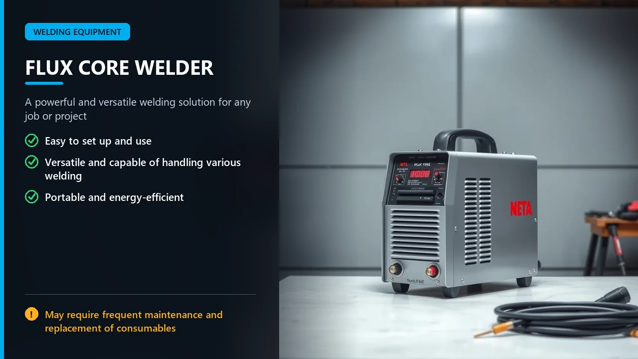
Key Takeaways: What This Guide Covers
Flux core welding sits at an odd intersection: it’s a wire feed process (like MIG), it produces slag (like stick), and it’s the only one of the three that walks outdoors into wind without complaint. Before the deep dive, here’s the short version of everything that follows:
- It’s a power source plus a feeder. A flux core welder is a constant-voltage power supply with a motor pushing tubular wire through a gun. The wire carries its own shielding, which is why no bottle is involved — our primer on what flux core welding actually is starts there.
- Constant voltage means the machine holds voltage and lets amperage follow you. Shorten the arc and amps climb; lengthen it and they fall. The machine self-regulates around your hand — see our settings guide for the working ranges.
- Duty cycle is a thermal rating, not a quality rating. Entry machines typically list 20–35% at rated output; mid-size units run 30–60%. It tells you how many of ten minutes the machine can weld before its own heat forces a nap.
- Input voltage decides your ceiling. A 110V machine realistically tops out around 140 amps; a 240V machine reaches 180–250+ amps, which is the difference between 3/8-inch single-pass work and 1/2-inch-plus fabrication. Compare the two in our 110V buyer’s guide.
- The feed system is where cheap machines give themselves away. Metal versus plastic drive gears, roll style, tension design, and liner quality decide whether your arc stays consistent at hour twenty.
- Setup is 80% of the result. Clean metal, correct polarity, right wire diameter, correct drive rolls, and a consistent stickout will out-perform any amount of hand skill fighting a bad setup.
- Know the failure modes. Most “machine problems” are actually settings, consumables, or supply-side electrical issues — our troubleshooting playbook covers the diagnosis loop.
- Respect the fumes and the code. Flux core makes more smoke than gas MIG, and the electrical demand is real; basic welding safety plus proper breaker sizing are non-negotiable parts of ownership.
What a Flux Core Welder Actually Is
Strip the marketing language away and a flux core welder is two machines bolted into one box: a power source that converts wall current into low-voltage, high-amperage DC, and a wire feeder that mechanically pushes a consumable electrode through a gun at a speed you control. The consumable is the part most people get wrong in their mental model. It isn’t a stick electrode with a coating; it’s a continuously fed tube of steel — a hollow wire, typically 0.030 or 0.035 inches in diameter — packed with powdered mineral compounds called flux. When the arc melts the wire tip, that powder decomposes into gas that shields the puddle and into slag that floats on top of the molten metal and protects it until it freezes. The shielding comes from inside the wire, which is exactly why the machine needs no gas cylinder, no regulator, no hose, and doesn’t care that the wind is blowing.
That single design fact explains most of the process’s reputation. Because the flux is inside the wire, the machine is portable, grab-and-go, and immune to the gusts that ruin a MIG welder’s day. Because the flux burns hot and throws slag, the process runs approximately 10–20% hotter than solid-wire MIG at equivalent deposition, spatters more, and leaves a coating you have to chip and brush before you can see what you made. Welding’s governing bodies draw the distinction cleanly: gas-shielded metal active welding is one process, flux cored arc welding is another, and they share a machine chassis but not a set of rules — TWI’s technical reference material is a good place to see how the industry separates them formally.
Inside the flux core family there are two sub-species, and confusing them is the most common source of “this wire doesn’t work” complaints. Self-shielded flux core wire — the kind sold in every hardware store spool — does all the shielding itself and runs on DC electrode positive. Dual-shield wire combines an internal flux with an external bottle of argon/CO2, runs hotter, deposits faster, and is a shop process rather than a driveway process. Almost every consumer flux core machine in this guide is built for the self-shielded variety. That’s what the different flux core wire types are for, and if you’ve ever wondered about the acronyms, FCAW is simply the formal name for what you’re doing with that spool.
Compare it to stick welding and the machine logic sharpens. A stick welder is a current source driving a consumable stick that burns away in your hand; the arc length you create by lifting and lowering the stinger directly changes the current, and the electrode is gone in a minute or two. A flux core machine takes that same self-shielding chemistry and puts it on a wire that never runs out, delivered by a motor at a constant rate, while the power source holds a steadier arc than most hands can hold a stinger. If you’re coming from stick, the learning shift is that your hands are no longer setting the arc length — the wire feed is — and your new variable is speed versus heat. Our stick versus flux core comparison digs into that transition in detail, and how strong flux core welds actually are answers the strength question people ask next.
The other comparison people arrive with is MIG, and it’s worth being precise because the machines are so similar. A typical consumer “MIG welder” can be switched to flux core mode: you reverse the polarity, swap the drive rolls, load flux core wire, and disconnect the gas. The arc behaves differently — flux core is a spray-ish, forceful arc with a slag blanket; gas MIG is a smoother, quieter arc you can watch directly. Whether the trade-off is worth it depends entirely on where you weld. We compare the two processes side by side in flux cored arc welding versus MIG, in flux core versus MIG head-to-head, and in the broader gas versus flux core showdown. The short version: outdoors, dirty metal, or no budget for gas, flux core wins; indoors on clean steel where appearance matters, gas MIG wins.
Power Source Theory in Plain English
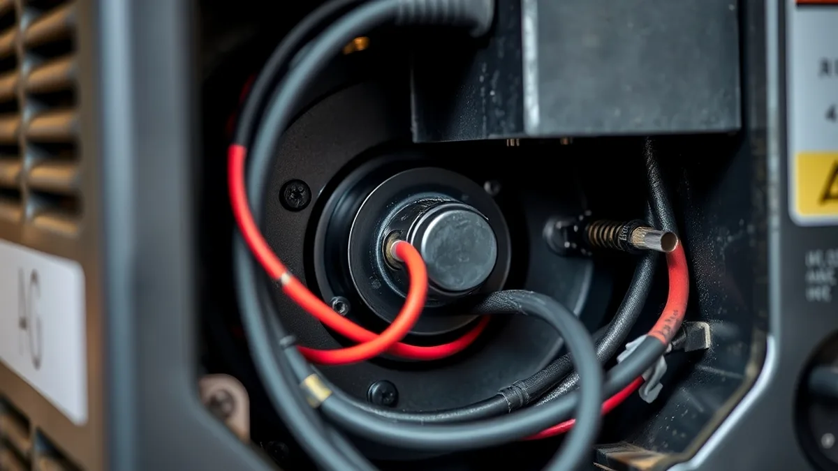
Every argument about welder quality eventually reduces to what’s happening inside that power source, so it’s worth slowing down here. Welding machines exist to do one job: take a wall outlet’s electricity and deliver it to an arc in a form that a human hand can control. Everything else — the fan, the case, the display, the brand decal — is packaging around that central act of conversion. Understanding the four core concepts below (constant voltage, amperage versus voltage, duty cycle, and inverter versus transformer architecture) will let you read any spec sheet on the market and know what the numbers promise and where the marketing is leaning on your ignorance.
Constant Voltage: The Machine That Won’t Chase You
Consumer wire feed welders — flux core and MIG alike — are constant voltage (CV) machines, sometimes called constant potential. Here’s what that means at the puddle: the machine aims to hold a steady arc voltage (you set it with a knob, typically somewhere between 15 and 25 volts), and it will supply however much amperage is needed to keep that voltage true. When you shorten the arc by moving the gun closer, resistance drops and the machine pushes more amps. When you lengthen the arc, resistance rises and the amps fall. The machine chases your hand automatically, several times per second, without you doing anything.
That self-regulating behavior is why wire feed processes are so beginner-friendly compared to stick. With a stick welder, the operator’s hand sets the arc length and the machine responds with a current you largely can’t feel changing; a millimeter of drift changes your penetration. With a CV wire machine, the wire’s own stickout becomes part of a feedback loop that stabilizes the arc, and the wire speed sets a practical floor on deposition. Practically, this means your main controls are voltage (arc length, wetting, bead profile) and wire speed (amperage, roughly — feed the wire faster and you’re asking for more current), which is a much smaller control surface to learn than stick’s simultaneous management of arc length, angle, and travel speed with a stick that’s disappearing as you go.
There is a trap inside the concept, though: constant voltage holds voltage, not heat. Swing the gun away from the work and the arc lengthens, the machine backs off the amps, and you get a cold, humped bead — while the machine reports that it is doing exactly what you asked. The same applies in reverse: crank voltage up chasing penetration and you get a longer, wetter arc with more spatter that has actually lost penetration at the toes. The amperage chart gives representative starting numbers by thickness.
Amperage Versus Voltage: Who Does What in the Puddle
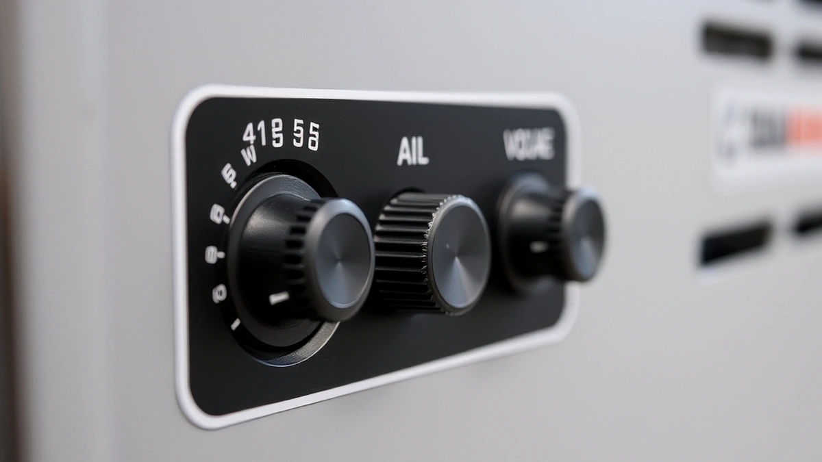
If you remember one technical relationship from this guide, make it this: amperage is heat input into the work, and voltage shapes the arc around that heat. Amps determine how deeply the base metal melts and how fast the wire deposits — that is penetration. Volts determine how far the arc reaches and how the puddle wets into the joint corners; too few and the bead sits proud with cold edges, too many and it goes flat, wide, and spattery. On a CV machine you rarely set amps directly: you set wire feed speed, and because the wire must melt at the rate it arrives, feed speed is a close proxy for amperage — twice the speed is roughly twice the metal, which needs roughly twice the current.
The rule of thumb the industry uses for self-shielded flux core is about one amp per thousandth of wire diameter: 0.030-inch wire wants roughly 30 amps to run properly, 0.035-inch wire wants roughly 35 amps at minimum — and then you scale up from there for the thickness you’re welding. That gives you the practical floor of any machine: if a welder’s minimum stable wire speed on 0.035 wire already demands more amps than the job wants (thin sheet metal, for instance), the machine is the wrong tool for that job no matter how good it is otherwise. It also explains why choosing between 0.030 and 0.035 wire matters more than it sounds like it should — the thinner wire lets small machines work on thinner material, the thicker wire runs more smoothly and handles structural work.
Volts, meanwhile, are where the “art” people talk about actually lives. A helpful mental model: think of amps as the size of the fire and volts as how tall the flame stands. You can have a big fire standing tall (high amp, high volt — thick plate, fast travel) or a small fire standing tall (low amp, high volt — thin metal, wetter puddle, high spatter) or a big fire held close (high amp, low volt — deep penetration, tight bead). Setting voltage is really setting arc length in tenths of an inch, and because flux core runs a stickout of roughly 1/2 to 3/4 inch — considerably longer than MIG’s 1/4 to 3/8 inch — your hand has more room for error but also more room for inconsistency. Lengthen the stickout and you change both the resistance and the shielding pattern, which is why the recommended stickout and gun angles are treated as fixed constants rather than preferences.
Duty Cycle: The Ten-Minute Honesty Test
Duty cycle is the spec most buyers skim and most owners learn the hard way. It’s a thermal rating expressed as a percentage at a stated amperage over a ten-minute period: a machine rated 30% at 130 amps can weld for three of the next ten minutes at 130 amps, then must idle for seven while its transformer or inverter sheds heat. Run it longer and the thermal protector trips — often with a click, a beep, or a red light — and the machine sits down until it cools. Nothing is broken when this happens; you’re simply watching the physics of copper losses, which is the honest price of pushing current through a circuit.
Entry-class 110V flux core welders typically publish 20–35% duty cycle at rated output, often at the top of their range (e.g., 30% at 140 amps means 30% at 140, but you might get 60–100% at 90 amps, because lower output means less heat generated per minute). Mid-tier and professional machines usually list 30–60%, and industrial diesel-driven units can hold 100% at rated amps indefinitely. Two things follow from this. First, the “rated amperage” a machine advertises is a peak, not a working continuous number — a 140-amp machine doing 3/8-inch plate at 130 amps is a three-minutes-on, seven-minutes-off proposition in theory, though real welding is staggered enough by fit-up and position that you rarely feel it. Second, you can buy effective duty cycle: a machine’s percentage improves dramatically if you weld at 80% of rated output instead of 100%, which is the practical version of increasing your duty cycle.
Duty cycle also explains a design decision that puzzles first-time buyers: why 240V machines feel so much more capable than their 110V siblings at similar advertised amps. At 240V, drawing 130 amps of output costs roughly half the input current, so the internal components run cooler, the fan works less, and the published duty cycle at that output is higher. Plus, at the same physical size, a 240V machine usually has a higher ceiling — and the ceiling is what you feel when you’re on your fourth pass and the thermal light comes on. When a machine does hit its limit repeatedly, the fixes are mundane: clean the fan filter, improve ventilation around the case, weld at a slightly lower setting, or stagger work so the machine cools between joints. Our duty cycle maximization guide covers the full list.
| Class of machine |
Typical published duty cycle |
What it means in practice |
| 110V hobby/entry (100–140A rated) |
20–35% at rated amps |
Roughly 2–3.5 minutes of welding per 10 at full tilt; near-continuous at 80–90 amps |
| 110/120V compact inverter (140–160A) |
30–40% at rated amps |
Comfortable for bracket work and repair; pauses during long seams |
| 240V mid-size (160–200A rated) |
35–60% at rated amps |
4–6 minutes per 10 at full output; continuous at typical 3/8-inch settings |
| 240V industrial/multi-process (200–250A+) |
40–60%, sometimes 100% at reduced amps |
Shop-fabrication friendly; won’t interrupt a root pass mid-weld |
Inverter Versus Transformer: What Changed Inside the Box
Older flux core machines — the 1980s-era CV boxes, the rounded steel cases that weigh as much as a transmission — are transformer-rectifier designs. They take the 60 Hz incoming AC, step it down with a big copper-and-iron transformer, rectify it to DC, and regulate the output with heavy contactors and, in many cases, mechanical range taps: coarse switches that select a band of output, with a smaller knob for fine adjustment within the band. The classic American tombstone stick welder and the early wire feeders of that era share this architecture. It’s robust, forgiving of dust and abuse, easy to repair at any shop that still stocks parts, and heavy — 60 to 130 pounds is typical for a serious unit. If you’ve ever hefted a Lincoln AC-225 style buzz box or read about transformer taps, you’ve met the old school.
Inverter machines do the conversion in the other order: rectify the incoming AC to DC first, then use high-speed switching transistors (IGBTs) to chop it into high-frequency AC, transform it at that much higher frequency — where transformers can be tiny — and rectify the output to DC. The result is a machine that delivers more usable output per pound, holds its settings more precisely, usually offers continuous adjustment rather than coarse taps, and can pack extra features (anti-stick, cold start, crater control, spool-gun support) into a microcontroller for very little added cost. A modern 140-amp inverter flux core machine weighs 20–30 pounds; the transformer machine it replaces in capability weighs two to three times that. Manufacturers have shifted almost entirely to inverters for consumer machines for exactly that reason, and the repair trade has shifted with them.
Both architectures weld fine, and the honest trade-offs are narrower than forum arguments suggest. Transformers tolerate abuse, heat, and dirty environments with a shrug; they also let you feel the arc through a certain heaviness that experienced welders describe fondly, and some processes (particularly stick with 6010) are traditionally easier on a constant-current transformer. Inverters win on portability, arc smoothness at low amperage, and feature density; their theoretical downside is that the power electronics are less tolerant of sustained overheating, dirty cooling paths, and cheap componentry — which is why the reputation of sub-$200 no-name inverters exists at all, and why a store-brand machine’s internals matter more than its spec sheet. Machines like the Eastwood 90-amp entry unit or the ubiquitous Reboot 135-amp class are all inverter designs; so are the Vulcan and Titanium lines that dominate weekend-welder shopping. The Miller resource library and Lincoln Electric’s technical pages both publish useful background if you want the manufacturers’ own framing of the technology.
Polarity: The Switch That Decides If the Wire Works
One last piece of power source theory, because it’s the single most common setup error in the field: polarity. Self-shielded flux core wire requires DC electrode positive (DCEP) — the wire is the positive side of the circuit, and current flows from the work back up into the wire, heating the wire tip more aggressively than the reverse. Solid MIG wire with shielding gas runs on DCEP too, but a number of dual-shield and some specialty wires specify DCEN (electrode negative), and many machines ship from the factory set for MIG with gas, which for flux core mode can mean the terminal connections on the wire feeder are reversed from where they need to be. The symptom of wrong polarity is characteristic and miserable: excessive spatter, erratic arc, poor penetration, and a bead that looks like it was formed by throwing metal at the joint.
Reversing polarity on most consumer machines is a two-minute job: swap the two terminal connections at the feeder (they’re usually clearly marked and tool-free), or flip the polarity switch on machines that have one, then verify with a test bead on scrap. It’s the first thing to check when a new spool of wire behaves badly, before you start blaming voltage settings or drive roll tension. Flux core polarity, explained properly walks through the terminal-level detail, and the related MIG polarity guide shows how the same switch governs gas-shielded work when you eventually convert the machine back.
The Feed System: Where Cheap Machines Give Themselves Away
The power source gets all the spec-sheet attention, but the wire feeder is what you actually feel while welding — the difference between a machine that lays a buttery bead at hour two and one that develops a stutter you cannot diagnose. The system is simple: a spool sits on a braked spindle, wire is pulled by a pair of driven rolls, pushed through a liner inside the gun cable, out the contact tip where arc current transfers, and into the puddle. Every component has a failure mode, and cheap machines cut costs exactly where failure starts: the motor, the gear train, the rolls, and the liner.
Start with the motor. Entry machines commonly use small brushed DC motors driving plastic gear trains, adequate for 1–2 pound spools and light duty — they work, but they develop backlash and inconsistency as the gears wear, and they struggle when the spool brake drags. Better machines use all-metal gear reducers and motors rated for continuous operation, sized to turn 4–8 or even 10 pound spools without straining. The tell is partly weight and partly behavior: a machine whose feed speed wanders as the spool empties, or one that hesitates on start-of-wire, has a feed system that’s marginal. Our wire feed motor guide explains what to look for and listen for, and the broader wire feed welder walkthrough covers the whole signal path from trigger to puddle.
Drive rolls deserve special attention because they’re the part beginners overlook. Flux core wire is a hollow tube — it’s softer than solid wire and crushes under excessive roll pressure, which then causes feed surges, birdnesting at the drive, and arc instability as the flattened sections pass through the contact tip. Most flux core machines do best with knurled or V-groove rolls with teeth or serrations that grip without needing to crush the wire flat; the wrong roll style (or a roll sized for 0.023 wire running 0.035) slips, shaves copper coating into dust, and feeds erratically. Rolls are cheap — $10–20 a pair — and swapping to the correct pair is one of the highest-return upgrades you can make. If you’ve never looked at yours, our drive roll guide shows what matched rolls look like and how to set tension so the gun can be bent 90 degrees without the wire stalling.
Then there’s the liner and contact tip: the liner is the tube the wire rides through inside the cable, and a kinked, contaminated, or worn liner adds drag that the motor has to fight (producing a pulsing feed you’ll hear as a rhythmic variation in the arc). Contact tips are consumables — the bore erodes with use, and an oversized tip bore gives the wire sloppy electrical contact, causing arc wander and erratic current. Replace tips when you notice instability, and replace liners on a schedule measured in hundreds of hours of use or whenever you switch wire types (contamination from one wire type to another is a real issue). Both parts cost less than a lunch and both are covered in our troubleshooting guide, which also addresses the classic feed complaints — birdnesting, wire burnback into the tip, and wire that won’t feed at all.
| Feed component |
Entry-class machines |
Better machines |
Failure symptom you’ll feel |
| Motor and gears |
Brushed DC motor, plastic gear train, 1–2 lb spools |
All-metal reduction gears, continuous-rated motor, up to 10 lb spools |
Feed speed drifts, hesitation at start, grinding noise as gears wear |
| Drive rolls |
Single V-groove, sometimes wrong size in the box |
Matched V-knurled or knurled pairs for flux core, quick release |
Slipping, shaved wire dust, surging, flattened wire entering the liner |
| Tension adjustment |
Coarse screw, marked loosely or not at all |
Indexed or detented tension with a clear neutral reference |
Birdnesting (too loose) or crushed wire and stall (too tight) |
| Liner |
Polymer, tight bend radius in short guns |
Steel spiral liners, proper length, serviceable |
Feed pulsing, high drag, wire curling on exit |
| Contact tip |
Threaded brass, replaced rarely |
Threadless or quick-change tips, correct bore size |
Erratic arc, burnback, spatter at the tip |
Wire range matters too: small 110V units feed 0.030–0.035-inch self-shielded wire, while 240V machines handle 0.030–0.045 and some reach 0.052 for heavy dual-shield work. Feeding capability is not just motor strength — it is the ability to hold constant speed against the drag of a partly empty spool, a gun bent around a corner, and a liner that has collected moisture, which is why a machine can feed perfectly on the bench and pulse when you are welding overhead with the cable doubled back.
110V Versus 240V: Choosing Your Input Voltage
This is the first fork in the buying road, and it’s less about the welder than about your building. A 110/120V flux core machine plugs into the outlet that already exists in your garage; a 240V machine needs a dedicated circuit that may not. The output difference is not subtle: 110V machines top out around 140–160 amps (and realistically sustain 120–140 with the duty cycle noted above), while 240V machines reach 180–250+ amps at comparable duty cycles and, critically, hold their settings more stably at the top of the range. Amperage is heat, so the ceiling determines the thickest material you can weld in a single pass and how quickly you can fill a multi-pass joint.
Here’s the math that surprises people: output amps don’t equal input amps. A 140-amp 110V machine at full tilt draws something like 14–18 amps from the wall at around 60–70% efficiency with a typical power factor, which is why it needs a dedicated 20-amp circuit (and why Dale’s shared 15-amp circuit tripped). A 200-amp 240V machine draws roughly 30–40 amps at 240 volts — the same physics, doubled voltage, halved current. That’s the whole reason 240V exists in welding: it doubles your voltage so you can draw twice the power through a wire that’s still a reasonable size. If you’re sizing a circuit, our breaker sizing guide and outlet guide give you the concrete numbers, and the wire gauge chart covers the copper run from panel to outlet.
| Factor |
110/120V flux core machine |
240V flux core machine |
| Typical output range |
30–140 amps (some reach 160 peak) |
30–200+ amps (heavy units to 250) |
| Wall draw at max output |
~14–18A on a dedicated 20A circuit |
~30–40A at full output on a 40–50A circuit |
| Realistic max thickness |
1/4″ comfortable, 5/16″–3/8″ with multi-pass |
3/8″ single pass, 1/2″+ multi-pass, structural work |
| Typical duty cycle at rated output |
20–35% |
35–60% |
| Weight |
15–40 lb, genuinely portable |
40–90 lb, cart territory |
| Installation cost if absent |
Usually none (existing outlet) |
$200–$800+ for a new circuit, depending on run |
| Generators required |
3,500–5,000 W running, depending on model |
6,500–10,000+ W running |
| Typical price band |
$130–$400 |
$350–$1,200 |
So which do you buy? If you’re welding sheet metal, doing driveway repair, hanging brackets, or building light furniture-scale projects, a 110V machine is genuinely sufficient — and its portability is a feature you’ll use constantly. If you plan to weld anything structural, work with 3/8-inch-plus material regularly, build trailers, or want headroom for multi-process expansion later, the 240V machine is the correct purchase on day one, even if the installation costs more than the welder. A useful heuristic: buy 240V if you already have or can easily add the outlet; buy 110V if the electrical work would be a project in itself. And if your welding happens where there’s no outlet at all — a field, a jobsite, a boat — then generator sizing becomes the deciding constraint, which is why we maintain separate guides for running a 140-amp welder on a generator, whether a 5,000-watt generator can run a welder, and how to estimate a welder’s wattage draw before you buy either machine.
One more electrical note for shop planning: three-phase machines show up constantly in used listings and auctions at attractive prices, but they won’t run on your home’s single-phase service without a phase converter or a transformer — and the converter usually costs as much as a new single-phase machine. Our three-phase to single-phase guide explains the trade-offs and the rare cases where converting makes sense, and the same caution applies to any “great deal” on industrial equipment that assumes industrial power. For context on where these standards come from, the NFPA codes (particularly the electrical code provisions for welder circuits) and AWS standards documents are the primary references your electrician and your employer will use.
How to Choose One: The Features That Actually Matter
Spec sheets are designed to make every machine look adequate, so decide in advance which few features actually determine your satisfaction and judge candidates against those alone. After enough bench time with entry-level and mid-tier machines the ranking stabilizes: feed system build quality first, because it is the component that degrades and the one you touch every second you are welding; amperage range and duty cycle second, because together they define what metal you can join and for how long; input voltage third; and everything else — display, color, accessories, brand heritage — trailing well behind. A $40 cart and a better mask are cheap fixes, whereas a feed system you dislike is not fixable at any price.
- Amperage range with a usable floor. Look at the minimum stable setting, not just the maximum. A machine rated 30–140 amps that won’t feed 0.030 wire smoothly below 40 amps is a sheet metal headache; one that runs a stable arc at 30 amps will handle body panels and thin tubing. Cross-check against our amperage chart before you buy.
- Duty cycle at the amps you’ll actually use. Read the fine print line: “35% at 130A” is a different promise from “35% at 100A.” If you plan to weld at 110–130 amps for 3/8-inch material, that’s the number to interrogate.
- Feed system construction. Metal gears, a motor sized for full spools, knurled or correctly matched drive rolls, indexed tension, and a serviceable liner. If a review mentions feed inconsistency, treat that as a dealbreaker, not a footnote.
- Input voltage decision, made once. Settle the 110V question before comparing models. If you’re staying on 110V, buy the strongest 110V machine in your budget — a best flux core welder under $300 list is a good starting field.
- Adjustment resolution. Inductance control (on machines that have it) softens or stiffens the arc character; a fine wire speed knob matters more than a coarse one. Machines with a printed settings chart on the inside door are quietly admitting that getting the numbers right is the whole game — we keep a fuller version in our settings reference.
- Parts availability and consumables. Contact tips, rollers, and liners wear out. A machine whose consumables are stocked by every welding supplier and hardware store in the country will cost you less over five years than an obscure import with a proprietary gun.
- Weight and form factor. If you’ll carry it up stairs, into trucks, or around a farm, 20 pounds versus 55 pounds decides how often the machine actually leaves the shelf.
Reviews compress this research nicely, but read them for what the reviewer actually tested: our beginner-focused buyer’s guide weights these features in purchase order, while head-to-head comparisons like Hobart Handler 125 versus 140 show two well-regarded machines differing on feed quality, adjustment granularity, and duty cycle rather than raw output.
Multi-Process Machines: Worth the Premium?
Many flux core welders are sold as multi-process units — flux core and MIG out of the box, often with stick capability and sometimes lift TIG thrown in. The honest assessment: the added hardware costs relatively little, since the machine already has a DC power source and a feeder, so multi-process is rarely a bad deal — but it does add a second set of consumables. A flux core-plus-MIG machine needs a gas bottle, a spool of solid wire, a second set of drive rolls, and the discipline to keep polarity switched for whichever mode you are in. People who weld both monthly love the format; people who buy it “someday” usually run flux core for years with a gas solenoid they have never opened.
The strongest argument for multi-process is the stick option: 6011 and 7018 capability lets the same box weld thick, dirty, out-of-position structural material outdoors — genuinely complementary rather than duplicative. Our Eastwood Elite MP140i review documents that format in detail. There is also a clean upgrade path: buy a single-process flux core machine now and add a stick welder later, because two cheap machines often outperform one compromised one.
Setup: From Cardboard Box to First Arc
Most disappointing first experiences with a flux core welder are setup failures misdiagnosed as skill failures, so the order of operations below matters as much as the steps themselves. Run them in sequence and your first session produces a usable bead instead of an afternoon of grinding: unpack, inspect the gun and ground clamp for shipping damage, check the polarity the machine ships in (it is very often set for MIG with gas), and confirm the outlet is dedicated and properly sized — our outlet guide walks the configurations. Then clean a section of scrap steel to bare metal, clamp it down, and practice there before touching the real project.
- Set polarity to DCEP for self-shielded flux core wire — swap the feeder terminals if the machine is wired for gas MIG. Wrong polarity is the number one cause of the “this wire is garbage” complaint.
- Load the spool with the wire unwinding over the top toward the drive rolls, set the spindle brake so the spool stops the instant you release the trigger (a spool that free-spins causes tangles), and thread wire by hand through to the feeder.
- Install correct drive rolls for the wire diameter and type, then set tension by the classic test: hold the gun trigger with the tip an inch off the plate — the wire should feed smoothly without slipping rolls (you’ll hear a rhythmic clicking) and should stall cleanly when you press the wire tip against the plate without buckling. Details in our drive roll guide.
- Trim the contact tip and stickout. Use a fresh tip, and cut the wire so the stickout from tip to work is roughly 1/2 to 3/4 inch for flux core — longer than MIG intuition suggests, because the flux needs room to generate its shielding envelope.
- Dial starting settings from a chart, not from hope. A representative starting point for 0.030 wire on 16-gauge to 1/8-inch steel is around 30–35 amps equivalent (moderate-low feed) with 17–19 volts; on 1/4-inch plate, 0.035 wire at roughly 90–110 amps with 20–22 volts. Tune by sound: steady frying means right, harsh crackle means too cold, aggressive popping with heavy spatter means too hot or too long an arc. Our wire-specific settings tables give full ranges.
- Practice four beads flat before the project: drag angle of about 10–15 degrees, gun roughly perpendicular, steady travel speed you can hold. Push or pull is a minor variable at this stage; consistency is the major one.
- Read the bead and adjust one variable at a time. Cold, humped, narrow: raise wire speed and/or voltage. Flat, wide, spattery, thin penetration: lower voltage and shorten stickout. The troubleshooting loop is deliberately one-variable-at-a-time so you learn what each knob does.
- Chip and brush the slag before judging the weld — flux core beads hide their sins under a crust, and porosity is often only visible after cleaning.
- Write down the settings that worked on a piece of tape on the machine. Future-you will not remember that 21 volts and 62% feed is the sweet spot for 3/16-inch tubing, and a settings log is the fastest path to a repeatable process. Our home practice guide turns this into a drill.
Real-World Capability: What Each Machine Class Can Actually Do
Marketing amps are one thing; what a machine will reliably do in a driveway with an amateur behind the gun is another. The ranges below are representative rather than model-specific — they assume self-shielded 0.030 or 0.035 wire, decent setup, and flat or horizontal positions, with the usual caveats that vertical and overhead work drop your practical thickness and that multi-pass changes everything. Read them as a map of the machine classes so you can place any specific model on it: a 140-amp 110V machine and a 200-amp 240V machine might both be advertised as “welders,” but they live in different regions of the metal-thickness map, and so do the projects you’re picturing.
| Machine class |
Amperage / feed range |
Comfort zone (single pass) |
Multi-pass / max practical |
Positions |
| 90–110A micro 110V (e.g. portable entry units) |
~30–110A; 60–350 IPM |
24 gauge–1/8″ steel |
3/16″ with 2–3 passes; rarely beyond 1/4″ |
Flat, horizontal fillet, light vertical-down; overhead is a struggle |
| 135–160A 110V workhorse (the most common class) |
~35–140A (peak 160); 70–450 IPM |
18 gauge–1/4″ steel |
5/16″–3/8″ with preheat and multiple passes |
All positions including vertical-up on 1/4″ and below |
| 180–200A 240V mid-size |
~40–200A; 75–550 IPM |
14 gauge–3/8″ steel |
1/2″–5/8″ with prep and pass sequencing |
All positions, all thicknesses; comfortable vertical-up |
| 200–250A+ 240V industrial / multi-process |
~45–250A+; 100–700 IPM |
10 gauge–1/2″ steel |
3/4″ and above with groove prep and interpass control |
All positions; production-rate structural work |
Position is the variable spec sheets never mention: vertical-up flux core needs a weave or a controlled pause rhythm and roughly 10–15% less heat than flat, overhead needs the lowest practical settings and short welds with cooling breaks, and every such adjustment moves you away from the advertised sweet spot. If your projects are mostly out-of-position — fence and gate posts, trailer frames, repair work under a vehicle — expect to live at 70–80% of the flat-rate numbers above. Specific workflows have their own tuning: vertical-up settings and horizontal settings are documented separately, and thin work — sheet metal and body panels — lives at the bottom of the range where 0.030 wire and a light touch are mandatory. The ceiling is a machine number; how much of it you can use depends on settings discipline, which is what our list of costly flux core mistakes is for.
Maintenance: Keeping the Machine Honest for a Decade
Flux core welders are mechanically simple, so maintenance is mostly cleaning and part replacement rather than repair — and the machines that survive fifteen years of garage duty are the ones whose owners do five unglamorous things on a schedule. Keep the cooling path clear by blowing out the fan intake and heatsinks every few months, because dust and welding spatter are what actually kill power electronics, not arc hours. Replace contact tips on wear rather than failure; a worn bore shows up as erratic arc long before it stops working. Inspect the ground clamp and its cable, since a poor ground forces the arc to compensate with erratic current. Check drive roll tension and the spool brake every time you change spools, and replace the gun liner when feed drag increases — then store the machine with a fresh inch of wire clipped so the tip cannot weld itself shut overnight.
Common Machine Problems and What’s Really Causing Them
Before you condemn a welder, walk the diagnosis loop, because almost every complaint reported as “the machine is broken” resolves at one of four layers: supply power, feed system, consumables, or settings. The list below maps the symptoms you actually see and hear to their usual causes, roughly in the order they should be checked.
- Wire won’t feed or feeds in surges: roll tension too tight or too loose, wrong roll size for the wire, a kinked liner, a dragging spool brake, or wire that has birdnested at the drive — all covered in the troubleshooting playbook.
- Wire burns back into the contact tip: stickout too short, voltage too low for the feed speed, a tip that’s worn oversized, or touching the tip to the work while the trigger is closed.
- Heavy spatter and a violent arc: wrong polarity first, then excessive voltage, too long a stickout, or contaminated base metal. Reducing spatter is mostly a settings and polarity exercise, not a technique one.
- Holes and bubbles in the bead: porosity from wind disrupting shielding, rusty or greasy base metal, wire that has absorbed moisture, or a feed interruption that let the puddle run dry — porosity explained covers the full list.
- Breaker trips within a minute: shared or underrated circuit, undersized extension cord, or the machine legitimately drawing full output on a 15-amp branch — see our breaker sizing guide.
- Thermal light comes on constantly: dirty cooling path, blocked fan, ambient heat, or sustained welding at the top of the machine’s rated range — a duty cycle issue rather than a defect.
- Feed motor runs but no wire moves: the rolls are slipping because tension is too light or the groove does not match the wire, or the wire has stripped a path through the liner — our wire feed motor diagnosis page separates the two cases.
How Flux Core Compares with Stick and MIG
No machine exists in isolation, and the three processes most buyers are choosing between — flux core, gas MIG, and stick — genuinely do different jobs well. Flux core’s edge is outdoor readiness, portability, and speed of setup: no bottle, no regulator, no drag behind you. MIG’s edge is control and cleanliness: the quietest arc, the lowest spatter, the easiest learning curve on clean steel, and the best bead appearance for anything that will be painted and displayed. Stick’s edge is penetration on dirty, thick, or out-of-position material with equipment that has almost nothing to fail — no wire, no liner, no drive rolls — which is why it still dominates pipeline and structural field work. Britannica’s overview of welding gives useful historical context for why these processes evolved separately, and our own stick versus MIG comparison and direct stick/MIG matchup dig into the same question from the buyer’s side.
| Consideration |
Flux core (self-shielded) |
Gas MIG |
Stick (SMAW) |
| Outdoor / wind tolerance |
Excellent — shielding is in the wire |
Poor — gas blows away above ~5 mph |
Excellent |
| Setup time |
Minutes: load wire, set polarity |
Load wire, bottle, regulator, flow check |
Fastest: clamp electrode, strike |
| Spatter and cleanup |
Noticeable spatter; slag must be chipped |
Lowest spatter; little to no slag |
Moderate spatter; heavy slag removal |
| Learning curve |
Easy arc, settings-sensitive |
Easiest overall |
Steepest — arc length is in your hand |
| Best thickness range |
16 gauge–3/8″ typical (110V–240V classes) |
24 gauge–1/4″ on 110V; wider on 240V |
1/8″–1″+ with the right electrode |
| Positional work |
All positions with tuned settings |
All positions, very controllable |
Outstanding in all positions |
| Consumable cost |
Spool only, no gas |
Wire plus bottled gas refills |
Electrodes, cheap and shelf-stable |
| Fume generation |
Highest of the three |
Lowest |
Moderate |
Most people resolve this with a sequence rather than a verdict: flux core first, because the machine is cheap and the process tolerates the imperfect conditions of a beginner’s workspace; gas MIG second as an upgrade path the same machine often supports; stick when you need its specific strengths. Our guide to flux core MIG welders explains the hybrid format.
Buying Guidance: Matching Machine to Mission
Work backwards from three real projects you plan to complete in the next year, then check each candidate machine against them — a method that reliably beats starting from a budget and browsing downward. Sheet metal, brackets, and light repair on a 110V circuit are handled by a compact inverter in the $150–$300 range; our under-$300 roundup and 110V roundup cover that field, and whether flux core welders are any good addresses the skepticism directly. Trailer frames, 3/8-inch structure, and anything welded in quantity call for a 240V machine from the start, because the cheapest 240V unit you trust will out-work the most expensive 110V unit on thick material every time. Store brands occupy the value sweet spot — the Vulcan versus Titanium debate is the standard example — while established brands cost 30–60% more for better support, longer duty cycles, and consumables you can buy anywhere, as our Harbor Freight assessment explains.
Safety and Electrical Requirements: The Non-Negotiables
Two systems deserve respect before the first arc: the circuit feeding the machine and the air you are breathing. Run the welder on a dedicated, correctly sized circuit — 20 amps at 120V for most 110V machines, 30–50 amps at 240V for mid-size units — with proper wire gauge for the run and a solid equipment ground; NFPA’s electrical code is the document your electrician works from, and our breaker sizing walkthrough translates it into outlet-level decisions. On the fume side, flux core generates more smoke than gas MIG, and those fumes contain zinc from galvanizing, manganese, and other constituents that are genuinely harmful with repeated exposure: OSHA’s welding, cutting, and brazing standards set the legal framework, NIOSH’s welding topic page summarizes the health evidence, and our guides on welding fume toxicity and respirator selection cover the practical response — ventilation first, a fitted P100 respirator second, and a helmet shaded for flux core work always. General welding safety rounds out the checklist: fire watch, gloves, sleeves, no welding in enclosed spaces without ventilation, and never welding sealed containers. For what long-term exposure means professionally, the BLS occupational profile and our article on welding and health put the risks in proportion.
Frequently Asked Questions
Does a flux core welder really work without gas?
Yes — that’s the defining feature of self-shielded flux core wire. The powder inside the tubular wire decomposes in the arc into a shielding gas envelope and a slag layer, so no cylinder, regulator, or hose is involved. The trade-off is more smoke, more spatter, and slag you must remove before inspecting the weld.
What thickness can a 110V flux core welder handle?
Comfortably up to about 1/4 inch in a single pass, with 5/16 to 3/8 inch achievable through multi-pass welding on a machine rated near 140 amps. Below roughly 20 gauge you’ll need 0.030 wire and the low end of the settings range; above 3/8 inch, a 240V machine becomes the sensible tool.
Can I run MIG wire in a flux core machine?
Not without shielding gas, and not on the polarity flux core requires. Solid MIG wire has no flux inside it, so it needs an external gas bottle and DCEP or DCEN depending on the wire — running it dry in flux core mode produces porous, weak welds. Our guide to mixing the two explains exactly why it fails.
Which wire size should I start with, 0.030 or 0.035?
Start with 0.030-inch wire if your machine is a 110V unit doing thin-to-medium work, because its lower amperage floor lets small machines run stable arcs on sheet metal. Choose 0.035 for 1/8-inch-plus structural work, where it feeds more smoothly and deposits faster. Our wire recommendations list specific consumables worth buying.
How long can a flux core welder run continuously?
Check the duty cycle plate on your machine: entry-class welders are typically rated 20–35% at maximum output, meaning two to three and a half minutes of welding per ten-minute window at full tilt. At 70–80% of rated output, most machines will run nearly continuously, which is how experienced welders avoid thermal shutdowns entirely.
Why does my welder keep tripping the breaker?
Usually because the circuit is shared, underrated, or feeding the machine through a thin extension cord. A 140-amp 110V machine at full output wants a dedicated 20-amp circuit on proper wire; a 16- or 18-gauge extension cord will cause voltage sag, overheating, and nuisance trips long before the welder is at fault.
Are flux core welds strong enough for structural work?
When welded with the correct wire, correct polarity, and full penetration, self-shielded flux core welds are code-recognized for many structural applications, and the deposited metal has mechanical properties comparable to equivalent stick electrodes. The variable is the operator and the preparation, not the process — see how weld strength is actually determined.
Do I need a special outlet for a flux core welder?
A 110V machine needs a standard grounded outlet on a dedicated circuit; a 240V machine needs a 3- or 4-prong 240V receptacle sized to its nameplate draw. Match the breaker, the outlet, and the wire gauge together rather than mixing components — our outlet guide shows each common configuration.
Can a flux core welder weld aluminum or stainless steel?
Aluminum is effectively out of reach: it requires an AC process, spool gun, and shielding gas, none of which a flux core setup provides. Stainless is possible with stainless flux core wire on a cleaned, dedicated liner, though MIG or TIG gives far better results — our stainless flux core guide covers the compromises.
Conclusion: A Small Box with a Long Ceiling
What makes a flux core welder worth owning isn’t raw power — it’s that the machine removes excuses. The shielding travels inside the wire, so wind doesn’t cancel the job; the feeder holds arc length for you, so imperfect hands still make sound metal; and the whole system fits in a box you can carry to the work instead of carrying the work to the shop. Understanding the power source underneath that convenience — what constant voltage is doing while you weld, why duty cycle is a thermal honesty rating, how an inverter differs from the transformer it replaced, and what your circuit has to supply — converts the spec sheet from decoration into a decision tool. Dale’s baler hitch never needed a master welder; it needed a machine matched to the job, set up correctly, and run inside its limits. That’s the entire discipline, and everything else in this guide — the feed system checks, the settings discipline, the maintenance schedule, the safety habits — is just what it looks like applied consistently.
Buy for the projects you actually have, on the voltage your building can support, with a feed system you will still like in year five. Set it up in the order laid out here, tune it by sound, and keep the machine fed with clean wire and clear cooling paths. Do that, and a modest flux core welder will outlive the projects you bought it for and keep pace with the ones you have not imagined yet.