Dev had spent an entire winter teaching himself flux core on a borrowed 140-volt machine, and almost every hour of it went into flat position. He burned through two spools running fillet coupons on the flat surface of his welding table, chasing the same fat, evenly rippled bead he’d seen in videos, and by March he could hit it pretty much on command. So when his uncle asked him to weld some 3/16 angle-iron braces onto a square-tube hay feeder that absolutely could not be taken apart, he wasn’t worried. Same wire, same machine, same joints he’d already done a hundred times — just standing up. He walked out to the barn, clamped the first brace at chest height, punched in the exact settings he had memorized for 3/16 flat, and within four inches understood that he had never actually welded before.
The puddle did something he had no language for. It hung fat and lazy along the bottom edge of the joint and sagged into a heavy rope that bulged past the toe, while the top of the joint — where the vertical plate met the horizontal brace — stayed a narrow, gray, frosty line that never seemed to wet into the upper member at all. He slowed down to give the metal more time to “flow in,” which made the sag worse and dropped two little icicles of steel onto the barn floor. He sped up, and the top toe went completely cold, a dry ridge you could catch a fingernail under. He turned the voltage up to get better wetting and blew a pit into the thinner wall of the tubing. He turned it down to control the sag and the wire started stubbing and popping back. Three grinds later he was sitting on an overturned bucket with a dirty forearm, staring at four inches of ugly and a sticky note full of numbers that all failed differently.
The save came from an old shop welder named Curt who wandered over, watched one pass, and didn’t let Dev touch the dials at first. He asked what position that was, and Dev said “horizontal, I guess.” Curt said, “Then why are you running flat settings into it?” The fix took ninety seconds: trim the voltage about a volt, drop the wire speed roughly ten percent from his flat numbers, bias the work angle up so the arc pointed harder into the upper plate, keep a 10 to 15 degree drag angle, and — the part Dev had been missing — move at a steady, slightly brisk pace instead of creeping. The next bead wasn’t pretty, but it was one bead, wetted into both toes. The one after that was genuinely good. Same wire, same gun, same operator; the only change was settings built for a joint where gravity is an active participant.
That story is this whole article in miniature. Horizontal is where most self-shielded flux core welders hit their first real wall, because it removes every safety margin flat position gives you: heat rises, metal sags, and a setting that is ten percent too hot sideways still produces something passable on the flat of the table. The good news is that the adjustment is systematic and small — usually a five to fifteen percent trim off your flat settings plus a handful of technique changes — and once you understand why the trim exists, you can derive it for any thickness instead of memorizing charts. Before we get to the numbers, it is worth being precise about what we even mean when we say a weld is horizontal, because the terminology trips up more people than the technique does.
Key Takeaways
- In welding position terms, “horizontal” is a formal designation: a 2F fillet weld has a horizontal weld axis on a joint made of a horizontal and a vertical member, while a horizontal groove weld (2G on plate) runs along a horizontal joint in plates that stand vertically — these are different joints with different settings.
- Self-shielded flux core must run on DCEP (electrode positive, often labeled “reverse polarity”); get this wrong and no amount of tuning the volts and wire speed will fix the bead.
- For horizontal fillets on mild steel from 16 gauge through 1/4 inch, start roughly 5-15% below your flat settings — about 0.5 to 1.5 volts lower and 10-20% lower in ipm — then tune from the bead.
- Gun angle matters more in horizontal than in flat: a 10-15 degree drag angle plus a work angle biased slightly toward the upper plate counteracts gravity’s pull on the puddle.
- Travel speed discipline is the single biggest fix — creeping lets the puddle sag, racing leaves the upper toe cold; a steady pace slightly faster than your flat speed usually wins.
- Flux core fume generation rises with amperage and enclosed work; horizontal positions often put your face closer to the plume, so ventilation and a proper respirator are not optional.
What “Horizontal” Actually Means in Welding Position Terms
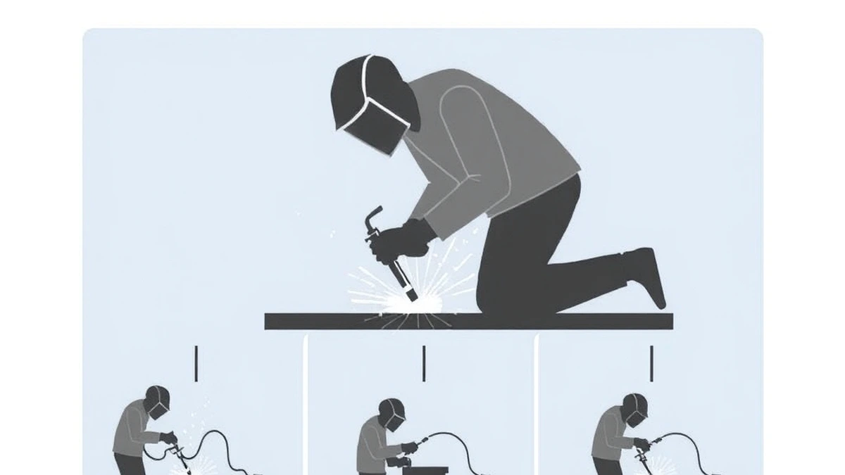
The first thing to clear up is that “horizontal” is not a vague description of standing up while you weld — it is a formal designation, and using it loosely is how people end up applying the wrong chart to the wrong joint. The first digit tells you the joint type: a 1 means a groove weld (a butt or V-groove where the weld metal goes into the joint between two members), and a 2 means a fillet weld (the triangular weld joining two surfaces at an angle, like a T-joint or lap joint). The second digit tells you the position: 1 is flat, 2 is horizontal, 3 is vertical, 4 is overhead. So a 1F is a fillet in flat, a 2F is a fillet in horizontal, a 3G is a groove run vertically, and a 2G is a groove run horizontally. If you want the formal definitions and the reasoning behind them, AWS standards publications are where the official language lives, and AWS D1.1 is the document most employers and inspectors are referencing when a position is written on a drawing.
For practical flux core work, the two horizontal joints you actually encounter are the 2F horizontal fillet and the horizontal groove, and they are geometrically different in a way that matters. In a 2F fillet, one member lies horizontal and the other stands vertical — a bracket on a frame rail, an angle brace on a square tube, a gusset on a column flange — and the weld axis runs horizontally along the corner where they meet. In a horizontal groove, both plates stand vertically and the groove faces sideways, so you are welding into a root that runs across a vertical wall: a repaired tank seam, a butt joint on a standing panel, a section of plate you could not lay flat. The distinction matters because the puddle behaves differently — in the fillet it is supported underneath but wants to roll down the vertical member, while in the groove it must stay inside the joint with nothing but surface tension and the frozen bead below holding it up.
There is a second axis of confusion, and it is the difference between the axis of the weld and the direction of progression. The axis is the imaginary centerline of the bead — for a horizontal weld, that line runs horizontally — while the direction of travel is how you move along it, leftward or rightward, and it is a separate decision from the position itself. In flat position you can choose either freely and it mostly comes down to visibility and comfort; in horizontal it interacts with gravity, because traveling one way means always depositing metal onto the leading edge of a puddle that is simultaneously trying to slump downward. Add a long horizontal seam welded in segments — stringer beads, skips, a root-and-fill sequence — and you can see why horizontal settings cannot simply be copied from a flat chart. If you are still building fluency with the fundamentals underneath all of this, flux cored arc welding techniques is a good place to shore up the base before specializing by position.
Why Horizontal Is a Different Problem Than Flat
Gravity is the obvious villain, but the honest explanation is that every condition supporting a flat puddle becomes asymmetrical the moment the joint tips. In flat position the weld pool sits in a shallow dish of its own making: surface tension holds it together, arc force pushes it into the joint, and the frozen metal behind it provides a shelf, so heat distributes evenly and both toes reach wetting temperature at roughly the same moment. Flip the joint to horizontal and heat now rises, so the upper region of the puddle stays hotter longer while the lower region freezes against cold base metal; molten metal wants to flow and pile at the bottom toe; and the arc delivers its energy to whichever member you happen to be pointing it at. The result looks like two different welds stacked on top of each other — a wet, sometimes saggy lower half and a dry, sometimes rolled upper half.
The asymmetry shows up first at the toes. The lower toe tends to over-wet: it spreads wide, gets a rounded, fat edge, and if you have pushed too much heat or moved too slowly, it rolls over into what’s called overlap — weld metal lying on top of base metal without actually fusing to it. The upper toe has the opposite problem. Because heat rises away from it and the puddle below is drawing molten material downward, the upper edge of the puddle often freezes before it can properly wash into the plate, leaving a cold, rough, gray seam that looks wetted but isn’t. This is the defect Dev saw in the barn, and it is the single most common reason horizontal welds fail visual inspection. If you want a deeper dive into reading these signals bead by bead, flux core welding troubleshooting walks through the same symptoms from the settings side.
Solidification direction is the second factor, and it explains why “just slow down” is bad advice in horizontal. As you travel, the puddle freezes from the cold base metal inward and from the trailing edge forward, while gravity constantly tries to move liquid toward the already-frozen lower toe. Slow down and you give that liquid more time to travel, so the bead grows tall and lumpy at the bottom; speed up too far and the upper region never reaches wetting temperature at all. There is a window, and it is narrower than in flat — commonly 10 to 14 inches per minute for a fillet on 3/16 material where flat might tolerate 9 to 18 — and it is centered slightly brisker than the flat pace you are used to. This is also why push or pull technique choices that feel irrelevant in flat suddenly change your results in horizontal.
Machine Setup Fundamentals Before You Touch a Single Setting

Settings only mean something if the machine behind them is configured correctly, and with self-shielded flux core the first check is polarity. That wire is designed to run on DCEP — direct current electrode positive, also called reverse polarity — because that polarity puts more heat into the wire and gives the arc the penetration and arc force the flux formulation expects. Most modern machines make this easy with a switch or a plug-in lead, but plenty of older and budget units default to electrode negative for MIG, and running flux core on the wrong polarity produces exactly the kind of confusing bead that sends people down a tuning rabbit hole: poor penetration, excessive spatter, an unstable arc, and slag that will not come off cleanly. If your machine does not label it, run a test bead and compare — the difference is dramatic, and flux core welding polarity covers the swap in detail. It is genuinely the first thing to verify when a horizontal weld refuses to behave.
The second check is machine sizing and duty cycle, because horizontal work has a way of turning a five-minute job into a twenty-minute job — grinding, repositioning, tacking, and re-running passes all eat into your arc-on time. A 140-amp 110-volt machine handles horizontal fillets up to about 3/16 inch on a single pass and can stretch to 1/4 with preheat and patience, but you will be near the top of its range when its duty cycle cuts in. Machines rated 180-200 amps or more give you headroom, which in horizontal terms means the ability to run slightly cooler settings and still hold the puddle — headroom is a technique asset, not just a thickness spec. The best flux core welders for beginners covers what matters at the entry level, breaker sizing matters as much as the machine itself, and how many watts a welder uses puts numbers on input power so you can stop guessing whether your supply is part of the problem.
The third check is the feed system, and it is the one people skip. Flux core wire is softer and more brittle than solid MIG wire, and it demands knurled drive rolls rather than the smooth V-grooves that come with many MIG-ready machines — smooth rolls pinch the wire and crush the flux inside it, causing erratic feed that shows up as arc stutter exactly when you are trying to hold a steady horizontal travel speed. Tension should be tight enough to push wire through a 10-foot gun without slip but loose enough that you can pull it out by hand with resistance and no deformation, and your stickout should sit around 1/2 to 3/4 inch because a longer one drops your actual amps. If the feed feels notched on a test pull, drive rolls for flux core wire will show you what is on your machine versus what should be — feed problems masquerade as settings problems constantly.
Wire Diameter Choices for Horizontal Work
Wire diameter is a settings decision disguised as a shopping decision, because it sets the floor and ceiling for everything else you dial in. For horizontal work on mild steel with self-shielded flux core you realistically have three options: .030, .035, and .045 — and .045 belongs on thick structural plate and machines with real amperage to burn it, so the practical choice is between .030 and .035, and it follows thickness more than it follows position. What changes in horizontal is how much margin each wire gives you: a wire slightly too large for the job gives a hotter, more fluid puddle that is harder to hold up, while a wire slightly too small forces you to run near the top of its range to get penetration, which is exactly when sag becomes a problem. A side-by-side breakdown lives in 030 versus 035 flux core wire, and it is the fastest way to settle the question for your stock.
The working rule I would give someone setting up for horizontal: .030 from 16 gauge up to about 1/8 inch, and .035 from 1/8 through 1/2 inch, with .035 being the better single-spool choice if you weld across a range of thicknesses. The reason .035 earns the nod for mixed work is not just higher deposition — it carries more flux per unit length, which makes the arc a bit more forgiving when your angle and travel speed are imperfect, and horizontal is exactly where those will be imperfect for your first few dozen hours. The trade-off is honest: .035 is harder to run on thin material without blowing through, and a 140-amp machine feeding .035 at 1/4-inch settings is working hard. Heavier wire also feeds more reliably through a longer or older gun, which matters when you are holding an awkward position and cannot afford stutter. Best flux core wire covers the consumable side, and flux core wire types explains how E71T-11 and E71T-1 formulations differ in what they ask of your settings.
One caution that horizontal makes uniquely relevant: stickout. Because amperage in wire-feed welding is a function of the resistance in the stickout, every extra half inch of wire hanging out of the tip drops your amps — and in horizontal, where people instinctively pull the gun back to see the puddle over the top of the nozzle, it’s common to see stickouts creep to an inch and a half. That’s easily 15-25 amps below your dial setting, which means your carefully chosen horizontal settings are actually running colder than you think, the upper toe goes cold, and you respond by turning things up until the bottom sags. Hold a consistent 1/2 to 3/4 inch, measure it on a test piece if you’re unsure, and only then start tuning voltage. The flux core amperage chart shows how amps track with wire diameter and stickout, and it’s the missing link between the number printed on your dial and what the puddle is actually receiving.
Settings by Thickness: 2F Horizontal Fillets
Here is the table this article exists to provide: self-shielded flux core, mild steel, DCEP, .030 or .035 wire, single-pass 2F horizontal fillet welds on T-joints and corner joints, with settings already trimmed from flat. Treat these as starting points, not commandments — machine brand, line voltage, gun length, and base metal condition all move the ideal a little, and the bead is the final judge. If your machine reads in heat and wire feed rather than volts and ipm, use the wire speed and voltage chart to translate, and note that the amps listed are typical arc amps at a 5/8-inch stickout, not the number on the dial.
| Material Thickness |
Wire |
Joint / Fillet Size |
Volts |
Wire Speed (ipm) |
Amps (approx.) |
Travel Speed |
| 16 gauge (0.063″) |
.030 |
1/16 fillet, square butt |
16.5 – 17.5 |
140 – 180 |
50 – 65 |
14 – 18 ipm |
| 14 gauge (0.075″) |
.030 |
1/8 fillet |
17.0 – 18.0 |
160 – 200 |
60 – 75 |
13 – 17 ipm |
| 11 gauge (0.120″) |
.030 or .035 |
3/16 fillet |
17.5 – 18.5 |
190 – 240 |
85 – 105 |
12 – 16 ipm |
| 1/8″ (0.125″) |
.035 |
3/16 fillet |
18.0 – 19.0 |
230 – 280 |
100 – 125 |
12 – 15 ipm |
| 3/16″ (0.188″) |
.035 |
1/4 fillet, single pass |
19.0 – 20.0 |
280 – 340 |
130 – 160 |
11 – 14 ipm |
| 1/4″ (0.250″) |
.035 (or .045) |
5/16 fillet, single or two-pass |
20.0 – 21.0 |
330 – 400 |
160 – 190 |
10 – 13 ipm |
Read across those rows a few times and a pattern shows up worth naming: from 16 gauge to 1/4 inch the voltage climb is only about four volts while wire speed more than doubles. That asymmetry is the core of wire-feed tuning — voltage sets the character of the arc (how fluid and wetting the puddle is), while wire speed sets the quantity of metal and, effectively, your amps. It matters in horizontal because the intuitive move when a bead sags is to reduce voltage, but if the sag is really caused by too much metal per inch of travel, the correction is lower wire speed or faster travel. When the upper toe will not wet, adding voltage helps only if enough metal is being fed to carry it — cranking volts with wire speed too low gives you a narrow, washed-out bead with undercut. Flux core welding parameters covers the interplay systematically if you are building an intuition rather than copying numbers.
A note on the low end of that table, because 16 and 14 gauge horizontal work is where beginners get hurt most. At 50-75 amps you are at the ragged edge of what a stable flux core arc can do, and horizontal makes it worse because you have less puddle mass to hold the arc. If you’re welding sheet horizontally and the arc keeps snapping off or the wire stubs, you’re not necessarily doing it wrong — you may be at the floor of the process. Two responses are legitimate: switch to .030 wire if you aren’t already, and consider whether flux core is the right process at all for very thin horizontal work. That’s a real trade-off, not a cheat — welding thin metal with an arc welder covers the alternatives, and welding sheet metal with flux core addresses the specific tricks (stitching, lower settings, faster travel) that make it work when you’ve decided to stay with the process.
Horizontal Groove and Butt Joint Settings
Groove welds in the horizontal position are a different animal from 2F fillets, because now the joint itself has to hold the puddle rather than a horizontal shelf doing it for you. A horizontal groove — 2G on plate, or a horizontal butt seam on vertical panels — means the root runs sideways, gravity pulls molten metal toward the bottom wall of the groove, and every pass you deposit becomes the ledge the next pass sits on. Fit-up matters far more here than in a fillet: a root opening that is too wide lets the first pass sag out the bottom, and one that is too tight produces lack of fusion at the root. The general rule is to run the root slightly cooler than flat and slightly faster, then let fill and cap passes come back toward — but not fully to — flat settings, because each pass inherits heat from the one below it. The table below gives typical ranges for a single-V groove with a 1/8-inch root opening.
| Plate Thickness |
Pass |
Wire |
Volts |
Wire Speed (ipm) |
Amps (approx.) |
Notes |
| 1/8″ (0.125″) |
Root (single) |
.035 |
17.5 – 18.5 |
210 – 250 |
95 – 115 |
Square butt, 1/16 gap; slightly faster than flat |
| 3/16″ (0.188″) |
Root |
.035 |
18.0 – 19.0 |
250 – 300 |
115 – 140 |
Stringer only; watch bottom wall for sag |
| 3/16″ (0.188″) |
Fill / cap |
.035 |
19.0 – 20.0 |
280 – 330 |
130 – 155 |
Two stringers side by side, no weave |
| 1/4″ (0.250″) |
Root |
.035 |
18.5 – 19.5 |
270 – 320 |
125 – 150 |
Keep root pass small and tight |
| 1/4″ (0.250″) |
Fill (2 passes) |
.035 |
19.5 – 20.5 |
310 – 370 |
150 – 175 |
Stagger toes; clean slag between passes |
| 1/4″ (0.250″) |
Cap |
.035 |
19.5 – 20.5 |
300 – 360 |
145 – 170 |
Bias work angle slightly up; trim from fill |
| 3/8″ (0.375″) |
Root + fill + cap |
.035 or .045 |
20.0 – 21.5 |
340 – 430 |
170 – 210 |
Multi-pass; interpass temp under 400 F |
Notice the volts column barely moves between root, fill, and cap on the same thickness — the root is cooler mostly because of wire speed and travel speed, not because you cranked the voltage down two whole volts. That is worth internalizing, because the classic beginner error in horizontal grooves is over-managing voltage and under-managing deposition rate. The root wants to be small, fast, and slightly underfilled so it does not hang out the bottom; fill passes want steady stringers with clean slag removal between them; and the cap wants to run slightly cool with the work angle biased toward the upper plate so it does not crown and undercut at the top. General flux core settings gives the flat baselines these numbers are trimmed from, and flux core welding tips covers the hand skills that make them deliver.
Flat Versus Horizontal: Exactly What to Trim and Why
Most welders who struggle in horizontal are running flat settings that are simply too hot for the joint, and they don’t realize it because the failure looks like a technique problem rather than a settings problem. The general adjustment is a five to fifteen percent reduction in heat input relative to your flat baseline for the same thickness and wire — typically 0.5 to 1.5 volts lower, wire speed down 10 to 20 percent, and travel speed slightly higher rather than lower. The range depends on joint type and thickness: thin material stays closer to the low end of the trim because you’re fighting burn-through as much as sag, while thick multi-pass work sits near the high end because you still need penetration into the root and you’ll be running several passes that each preheat the last. The comparison table below shows the logic side by side for a representative 3/16-inch fillet, which is thick enough to show every variable clearly and common enough that most shops hit it daily.
| Variable |
Flat (1F) Baseline |
Horizontal (2F) |
Why It Changes |
| Voltage |
19.5 – 21.0 V |
19.0 – 20.0 V |
Lower heat keeps the puddle viscous enough to resist gravity’s pull |
| Wire speed |
330 – 400 ipm |
280 – 340 ipm |
Less metal per inch prevents the lower toe from building and sagging |
| Arc amps (approx.) |
150 – 175 A |
130 – 160 A |
Follows the wire speed trim; roughly 10% below flat |
| Travel speed |
9 – 12 ipm |
11 – 14 ipm |
Faster pass means less time for liquid metal to slump |
| Work angle |
45 degrees (equal legs) |
50 – 55 degrees (biased to upper plate) |
Directs arc heat upward to wet the cold top toe |
| Drag angle |
10 – 20 degrees |
10 – 15 degrees |
Shorter drag keeps the arc digging into the joint instead of pushing metal downhill |
| Stickout |
1/2 – 3/4″ |
1/2 – 3/4″ (strictly held) |
Variation drops amps unpredictably; horizontal punishes it faster |
| Pass strategy |
Often single pass |
Often two smaller passes |
Splitting the volume keeps each puddle shallow enough to hold |
The travel-speed row deserves a second look, because it runs opposite to what most people expect. Almost every beginner’s instinct in horizontal is to slow down — the logic being that a slower, more careful hand will give the metal time to fuse — and that instinct is exactly backwards. Slower travel means more amps delivered per inch of weld, a larger and more fluid puddle, and more time for liquid to migrate downward before it freezes; it is the single most reliable way to produce a saggy lower toe with a cold upper toe on the same bead. The correct correction when a horizontal weld looks wrong is almost always some combination of slightly less heat and slightly more speed, not more patience. If you’ve never deliberately practiced speed control, practicing welding at home lays out drills that build the hand speed as a skill rather than a guess, and welding tips for beginners covers the foundational habits that make position-specific tuning click.
Gun Angle and Work Angle: The Part Nobody Puts on a Chart
Every settings chart in the world is incomplete without gun angle, because angle changes where the arc energy actually lands, and in horizontal that redistribution is the whole game. Two angles are in play at all times. The travel angle (also called the drag or work-motion angle) is how far the gun tilts from vertical relative to the direction of travel — for self-shielded flux core, you drag rather than push, so the gun points back toward the finished bead at roughly 10 to 15 degrees off vertical for horizontal work. That is a touch shorter than the 15 to 20 degrees many welders use in flat, and the reason is that a steeper drag in horizontal drives the arc force downward along the joint, helping gravity pile metal at the bottom toe. Shorten the drag, keep the arc digging forward into unfused metal, and you get better root penetration with less downhill migration. Where a corner or inside joint forces an awkward attack angle, grinding inside corner welds covers how to prep the joint so the gun can sit where it needs to instead of where your wrist happens to be.
The second angle is the work angle — how the gun is oriented relative to the two members of the joint — and this is where the gravity compensation lives. On a 2F fillet in flat position you point the gun at 45 degrees so both legs of the fillet come out even; in horizontal position, aim slightly high, at 50 to 55 degrees toward the upper plate, enough that the arc preferentially heats the member that is otherwise staying coldest. The visible result is that the upper toe washes in and fuses, while the lower toe, which was already receiving extra heat from the molten metal sitting on it, stops over-wetting. The trade-off is that the upper leg can come out slightly longer unless you compensate with a touch of travel speed, and on visible work you may want to split the difference at 48 to 50 degrees. Getting this right takes reps more than theory — flux cored arc welding techniques breaks down the hand positions that make the angle repeatable.
Travel Speed Discipline in Horizontal
Travel speed is the variable that holds a horizontal weld together, and the discipline differs from flat: in flat a range of speeds usually produces acceptable beads, while in horizontal the pace has to be steady within a narrow band for the whole pass. The puddle is simultaneously freezing at the trailing edge and trying to flow at the leading edge, so any hesitation in your hand tips that balance. Pause half a second and you get a lump; surge and you get a cold, ropey section where the arc outran the puddle. The practical answer is a pace you can repeat — pick a mark on the joint and cross it at a consistent rhythm, or use the arc itself as a metronome: a steady frying-bacon crackle that never changes pitch. Quiet and soft means you are too slow and the arc is buried; sharp and spitting means you are too fast or too far out.
How fast is fast enough? For single-pass horizontal fillets on mild steel with .035 wire, something in the 10 to 14 inches-per-minute range covers most thicknesses from 3/16 to 1/4, and thin material runs quicker — 14 to 18 ipm on 14 and 16 gauge. Compared to flat at the same thickness, that is typically 10 to 20 percent quicker, which surprises people who assumed horizontal meant more careful and therefore slower. A quick calibration: lay a flat bead at your usual comfortable pace, then run the horizontal bead at the same pace with the trimmed settings from the table above, and adjust from there — if the bottom is building, speed up before you touch the dials. Technique first, then settings, prevents the endless dial-chasing that ruins so many first attempts, and it is a theme costly flux core mistakes keeps returning to.
Root Pass and Multi-Pass Strategy in Horizontal Grooves
Multi-pass horizontal groove work is where settings discipline turns into sequencing discipline, and the sequence matters more than any single dial position. Start with the root. In a horizontal groove, the root pass has to bridge the gap and establish a shelf without hanging out the bottom of the joint, which means it should run slightly underfilled, slightly cooler, and slightly faster than a flat root would — use the root row from the groove table above, keep the bead narrow (a stringer, never a weave), and watch the bottom wall of the groove for the first sign of droop. If the root sags, the fix is faster travel and less wire, not less voltage; if the root sits cold and ropey on the upper side, shorten your stickout and bias the work angle up before you change anything else. A root that comes out clean and flat is worth more than any amount of perfection on the cap, because every subsequent pass inherits its geometry.
After the root, fill with stringer beads laid side by side and slightly overlapping — never weave on anything structural in horizontal, because a wide weave puts the puddle’s center of mass too far from its supporting edges and the middle will sag while the sides stay put. On 1/4-inch plate expect two fill passes plus a cap; on 3/8 expect three to five depending on groove width. Stagger the toes so each pass overlaps the previous by roughly one-half to two-thirds, and check that each pass fuses into the last without a visible seam after slag removal. Clean the slag thoroughly between passes — this is not optional, because slag trapped in the concave lower corner of the groove is the number-one source of lack-of-fusion inclusions in sideways welds, and reducing flux core spatter and slag discipline go hand in hand. If you are working from a drawing, reading welding blueprints tells you how many passes the joint calls for before you start stacking them.
Heat management is the quiet partner in this sequence. Every pass you lay raises the interpass temperature of the joint, so pass three is already running hotter than pass one at identical dial settings — the same 20 volts that gave you a controlled root will give you a fluid, saggy cap if you have not accounted for the accumulated heat. Hold interpass temperature under roughly 400 degrees Fahrenheit for mild steel, let the joint cool between passes when you can, and trim the cap settings about 5 percent below the fill settings if you are working continuously. Distortion deserves the same attention: a horizontal seam on a standing panel pulls the plate out of square more visibly than a flat seam, so alternate the ends of a long seam rather than running it start to finish. For context on what each of those passes contributes, how strong a weld is and whether flux core welding is strong address penetration and pass sequence directly.
Common Horizontal Defects: Causes and Fixes
Horizontal welding produces a remarkably consistent catalog of failures, and the useful thing about that is that each one points to a specific correction rather than a vague “work on your technique” verdict. The table below is the diagnostic map I’d keep taped inside the machine door: find the symptom, confirm the cause, apply one fix, and run a test bead before changing anything else. The most important rule when troubleshooting is to change one variable at a time — the classic failure mode is turning down the voltage while also speeding up while also changing angle, ending up with a new problem you can’t attribute to anything. And when a defect shows up as holes rather than shape — wormholes in the root, pinholes after slag removal — start with porosity in welding before you touch a single dial.
| Defect |
What It Looks Like |
Likely Cause |
The Fix |
| Cold or rolled upper toe |
Gray, rough, frosty seam along the top edge; bead visibly not fused to the upper plate |
Heat and metal both migrating downward; work angle aimed too low; settings too cool for the top of the joint |
Bias work angle 50-55 degrees toward the upper plate; trim stickout; add 0.2-0.5 V; speed up slightly |
| Lower-side sag / heavy rope |
Wavy, bulging bead along the bottom toe; possible icicles or droplets |
Too much heat input per inch; travel too slow; wire speed too high; puddle too fluid |
Reduce wire speed 10-15%; travel faster; drop voltage 0.5 V; split the weld into two smaller passes |
| Undercut on upper toe |
Groove carved into base metal right at the top edge of the weld |
Voltage too high combined with a slow, wandering travel speed; angle pointed too directly at the vertical member |
Lower voltage slightly; steady the pace; shorten drag angle to 10 degrees; widen the bead slightly at the top |
| Overlap at lower toe |
Rounded, non-fused lip of weld metal lying on the base metal at the bottom |
Too much filler per inch of travel; travel too slow; work angle aimed too low |
Increase travel speed; reduce wire speed; shift work angle up so the arc doesn’t pile metal downhill |
| Porosity or wormholes |
Small holes, tunnels, or elongated pockets after slag removal |
Dirty or painted base metal; inconsistent stickout; too-fast travel trapping gas; wind blowing shielding away |
Clean to bright metal; hold stickout constant; steady the pace; shield the area from drafts |
| Stubbing / erratic arc |
Wire jams at the tip, arc stutters, popping back |
Wrong polarity; wrong drive rolls; liner friction; stickout too short; contact tip too large |
Verify DCEP; fit knurled rolls; check the liner; hold 1/2-3/4″ stickout; match tip to wire |
| Lack of fusion at root |
Cold, unfused line visible in a groove after break-out or inspection |
Root too cool; travel too fast at the root; insufficient heat because of long stickout |
Shorten stickout; slow slightly at the root only; verify polarity and actual arc amps |
| Spatter-heavy, violent arc |
Balls of spatter across the plate, harsh crackle |
Voltage too low for the wire speed; wrong polarity; contaminated wire; stickout too short |
Balance the two dials using a test bead; verify DCEP; check wire storage; lengthen stickout slightly |
Two of those rows deserve extra commentary because they are the ones people misdiagnose most often. Cold upper toe is almost never fixed by turning voltage up alone — if the metal fed per inch is too great, extra voltage just makes a wider bead that still freezes at the top while sagging more at the bottom. The combined correction — angle up, slightly more voltage, slightly less wire, slightly faster hand — addresses all three causes at once; changing only one usually trades one defect for another. Lower-side sag is just as often blamed on bad wire or a cheap machine when the real cause is travel speed, because sag is a time problem: the longer liquid metal exists, the further it moves. Run the same joint ten percent faster with identical settings before you replace anything. If spatter dominates instead, spatter reduction techniques and the troubleshooting guide walk the same table, and common flux core mistakes shows how these defects bunch together in one bad pass.
Thin-Material Horizontal Stitch Technique
Welding 16- to 14-gauge sheet in the horizontal position is the scenario where settings and technique have to work together most tightly, because the margin between fused and blown through is roughly one amp wide and gravity is doing its worst. The technique that works is stitching: rather than a continuous bead, run short segments — typically 1/2 to 1 inch long — with a brief pause between them, letting each segment cool enough that the next one does not push the whole seam into a molten state. The settings from the thin rows of the fillet table (16.5 to 18 volts, 140 to 220 ipm, .030 wire) are your starting point, and the discipline lives in the pause length: too short and the segments merge into a continuous hot pass that sags; too long and you get isolated lumps with cold restarts between them. The rhythm is segment, lift, reposition, segment — never holding the trigger while hovering on a half-melted puddle.
Direction and sequencing matter more on thin horizontal work than on anything thicker: choose a direction that keeps you moving onto cold metal rather than onto a puddle you just made, and alternate segments across the seam (skip welding) when the panel is long enough to distort. On a lap joint, put the stitch on the edge of the top sheet so the arc cuts into it cleanly instead of drowning it; on a T-joint, keep the bead small enough that the whole fillet is one stitch width rather than trying to build a 1/4-inch fillet in a single horizontal pass on 16 gauge. Pre-tack generously — four to six tacks per 12 inches — because tack shrinkage holds the joint closed while you stitch, and gaps are the enemy of thin horizontal work. Everything about this gets easier if your feed system is honest, so working with a wire feed welder and sheet metal with flux core are worth reading before you fight a job that thin.
There’s an honest trade-off to state: flux core is the hardest of the common processes to use on thin horizontal sheet, because the process runs hotter and more aggressively than gas-shielded MIG at equivalent settings and the slag coating hides the puddle exactly when you most need to see it. If your project is mostly thin sheet in awkward positions, what flux core welding actually is and gasless flux core wire welding both cover where the process shines (outdoors, dirty metal, field repairs, thicker material) and where it doesn’t. Flux core versus solid wire lays out the process choice itself. And if you decide the job really wants a different process, that’s a judgment call, not a failure — knowing the limits of your consumables is part of the skill. When the material is galvanized rather than plain steel, add another variable: welding galvanized steel with flux core covers the zinc contamination issues that make thin horizontal work even fussier.
Material Prep for Horizontal Joints
Preparation is where horizontal welds are quietly won or lost, because a joint that fits well gives the puddle something to hold onto and a joint that does not forces your settings to compensate for a problem they cannot fix. For horizontal fillets the checklist is short but strict: grind or wire-brush both members back to bright metal for at least an inch either side of the joint, remove heavy mill scale (light mill scale is acceptable for flux core, but paint, oil, primer, and rust are not), and square the edges so there is no visible gap at the root. On T-joints and corner joints, clamp or tack so the pieces stay in contact — a gap of even 1/16 inch lets the root fall through to the bottom side while the top toes stay cold, which reads as a settings problem and is actually a fit-up problem. Cleanliness has a direct settings consequence too, because contamination creates gas that the horizontal puddle cannot release as easily.
Groove joints demand more: a consistent root opening (1/8 inch is a common target for plate up to 1/4), a uniform land and bevel angle so the root face is the same width along the whole seam, and back-grinding of the root where fit-up is loose enough to put full penetration at risk. Tack the groove at both ends and midway, and tack on the back side where access allows, because horizontal grooves open up as you weld — contraction forces in a standing panel pull the root gap wider as you go, and a gap that grows mid-pass is how a root ends up sagging out the bottom. If you are working from a drawing, reading welding blueprints gives you the required joint prep and weld size before you cut anything, and full penetration versus fillet explains when a simple fillet is enough versus when the joint needs a prepared groove to carry the load.
Safety and Ventilation for Horizontal Flux Core Work
Flux core welding generates more fume than almost any other common process, and horizontal positions quietly make exposure worse because your breathing zone tends to sit directly in the plume’s path — you are often working at chest or head height with your face a foot from an arc throwing smoke straight up into it. The fumes come from the flux burning, from base-metal coatings, and from zinc oxides if any galvanized or plated steel is in the joint, and they are not something to power through. The first line of defense is ventilation: for anything beyond short tack welds, work outdoors or in a drafty open shop where the plume disperses, and for repeated or enclosed work use local exhaust — a fume extractor arm pulling smoke away from your face rather than relying on general shop airflow. OSHA’s welding, cutting, and brazing standards set the requirements employers are held to, and NIOSH’s welding health topics summarize the evidence behind them.
The second line of defense is respiratory protection, and it matters most on exactly the jobs this article covers — overhead-height horizontal seams where the plume rises into your face, indoor work where fume pools, and any job involving coatings. A properly fitted half-mask respirator with P100 (and, where metal fume fever is a risk, an appropriate fume cartridge) is the baseline for garage welders; if you weld often or in tight spaces, a supplied-air or PAPR-style hood is a genuine upgrade rather than a luxury. Fit matters more than the filter rating — a respirator that leaks around the cheeks protects you almost not at all — so take the time to learn welding safety basics and pick equipment you’ll actually wear, starting with respirator options. For the health picture in more depth, are welding fumes toxic and is welding bad for your health both address the long-term question straight rather than hand-waving it.
Beyond fume, standard PPE applies with a couple of horizontal-specific notes: a helmet with the right shade for your amperage (flux core’s bright arc and heavy spatter justify going one shade darker than you would use for stick at the same amps), flame-resistant clothing with no exposed cuffs or gaps, and gloves that let you hold a consistent gun angle without hand fatigue. Horizontal spatter falls and rolls along surfaces rather than dropping straight down, so it finds gaps in sleeves and collars more easily than flat-position spatter does. Add eye protection under the helmet for grinding, a welding screen if anyone else is in the space, and a fire check of the area behind and below the joint — slag and spatter land on ledges, inside tubing, and behind panels where they can smolder unseen. The formal practice documents, if you ever need them for a shop procedure, live in the AWS standards library.
Frequently Asked Questions
What settings should I use for horizontal flux core welding?
Start from the tables above: for a single-pass 2F fillet on 3/16 mild steel with .035 wire, about 19.0-20.0 volts, 280-340 ipm, and 130-160 arc amps at a 5/8-inch stickout, with travel around 11-14 inches per minute. Those numbers are already trimmed roughly 10 percent below flat. Dial them in with a test bead on scrap of the same thickness, then adjust one variable at a time based on what the bead tells you — the wire speed and voltage chart helps if your machine uses different units.
Why do I have to run lower settings in horizontal than in flat?
Because horizontal asks the puddle to do two jobs at once: fuse into the joint and resist gravity. Lower heat input makes the puddle more viscous so it stays where the arc put it, and less wire per inch keeps the lower toe from building up while the top toe catches up. Run flat settings sideways and you get the classic combination of a saggy bottom and a cold top — two defects from one cause.
Does self-shielded flux core need DCEP in the horizontal position too?
Yes — polarity doesn’t change with position. Self-shielded flux core runs on electrode positive (DCEP, or reverse polarity) no matter which direction you’re welding, and running it on electrode negative gives you poor penetration, heavy spatter, and slag that won’t release, all of which look like settings problems in horizontal. Verify the polarity switch or lead connection before you tune anything else; flux core polarity covers the details.
Should I use .030 or .035 wire for horizontal welds?
Use .030 from 16 gauge to about 1/8 inch, and .035 from 1/8 inch up through 1/2 inch. .035 is the better all-around choice for horizontal work because it carries more flux per inch, which gives a slightly more forgiving arc when your angle and speed aren’t perfect yet — but it’s harder to run on thin sheet without blowing through. The .030 versus .035 comparison goes deeper.
Why does the bottom of my horizontal weld sag while the top stays cold?
That is the signature horizontal failure and it has three causes: too much heat and metal per inch, travel speed too slow, and a work angle aimed too low so arc energy lands on the bottom member. Fix all three together — reduce wire speed 10 to 15 percent, speed up slightly, bias the work angle to 50 to 55 degrees toward the upper plate — rather than turning one dial and hoping. Then change one variable at a time from that combined starting point so the diagnosis stays clean.
Should I weld left-to-right or right-to-left in the horizontal position?
Direction is less important than consistency, but with flux core you drag (the gun points back toward the finished weld), which usually means right-to-left for a right-handed welder facing the joint. Whichever direction you choose, keep the drag angle short — 10 to 15 degrees — and keep the arc digging into unfused metal rather than pushing a puddle ahead of you. On long seams, pick the direction that lets your body move smoothly along the joint instead of reaching.
How do I stop undercut along the upper toe of a 2F fillet?
Undercut at the top comes from too much voltage paired with a travel speed that’s too slow or unsteady, so the arc carves a groove into the vertical member faster than filler metal fills it. Drop voltage 0.5 volt, shorten your drag angle, and smooth out your pace; if the bead is narrow, a slightly wider, faster pass spreads the heat instead of concentrating it in one spot. Increasing wire speed slightly also helps fill the groove the arc is cutting.
Can I weld 16-gauge sheet in the horizontal position with flux core?
You can, but it’s the hardest combination in this article: run .030 wire at about 16.5-17.5 volts and 140-180 ipm, stitch in 1/2- to 1-inch segments with pauses, and tack the joint heavily first. Flux core runs hotter and hides the puddle behind slag, so if your project is mostly thin sheet, consider whether gas-shielded MIG would serve you better — thin metal techniques covers the alternatives honestly.
How many passes does a horizontal groove weld need?
It depends on thickness and groove width: one pass for a 1/8-inch square butt, a root plus one to two stringers for 3/16 plate in a V-groove, root plus two fills plus a cap for 1/4 inch, and three to five total on 3/8. Never weave the fill in horizontal — lay stringers side by side with half-to-two-thirds overlap, clean slag between passes, and let the joint cool below about 400 degrees Fahrenheit between passes.
How do I reduce spatter when welding horizontally?
Spatter in horizontal usually means the two dials are out of balance — most often voltage too low for the wire speed, or a stickout that’s too short — plus whatever contamination is on the metal. Balance the settings on a test bead, hold stickout at 1/2 to 3/4 inch, verify DCEP, and clean the joint. If spatter is chronic regardless of settings, check your drive roll tension and wire condition first; spatter reduction walks through the full checklist.
Conclusion: Turning the Setting Into a Judgment
Go back to the barn for a moment. Dev’s problem on that hay feeder was never his machine, his wire, or his ability — it was that he had exactly one set of numbers (his flat numbers) and no model for what changes when the joint tips ninety degrees. The adjustment that fixed it was almost comically small: about a volt off the top, ten percent off the wire speed, the gun biased toward the upper plate, a 10 to 15 degree drag, and a slightly brisker, steadier hand. That is the entire delta between a flat weld and a horizontal one for most of the work you will do — five to fifteen percent less heat, a little more speed, and an angle that argues with gravity instead of agreeing with it. Everything else in this article is elaboration on that core move.
The deeper skill being built here is judgment rather than memorization. Charts get you to a starting point; beads tell you the truth. Run a test pass, look at both toes, ask which one is cold and which one is fat, and make the one correction that addresses the actual cause — angle, speed, or heat, in that order, touching the dials last. Do that twenty times and horizontal stops being the position where things go wrong and becomes just another joint you can read. For structured reps, practicing welding at home and the broader flux core technique library build the hand speed and angle control this article assumes, the FCAW fundamentals page ties the process together from the top, and TWI, Miller’s resource library, Lincoln Electric, and Britannica’s welding overview are the reference sources worth bookmarking alongside them.
One last thing worth remembering from that afternoon in the barn: the weld that finally worked was not the result of a magic setting. It was the result of a diagnosis — position identified, cause identified, three small corrections applied in order. Gravity does not stop working when you strike an arc, and no setting will make horizontal behave like flat. What settings do is give you a puddle viscous enough to hold, fed enough to fuse, and aimed well enough to wet both toes; everything past that is your hand. Dial in from the tables, watch the toes, adjust one variable at a time, and the next hay feeder takes an afternoon instead of a weekend.