Saturday morning, 7 a.m., and I had one job before noon: a pair of steel driveway gates for a neighbor who was paying in cash and barbecue. The frame was 1-inch square tube, the wire was a cheap spool of self-shielded flux core, and the first pass looked great until I flipped my helmet up. Every square inch of the surrounding metal was freckled with grape-shot pellets of frozen steel. Spatter in the hinge holes, spatter on the powder-coated post caps I had already installed, spatter welded into the very surface I was supposed to deliver clean. What should have been a two-hour build turned into an afternoon of grinding, filing, and explaining to my neighbor why the “finished” gate looked like it had been sandblasted with gravel.
That is the quiet tax of flux core welding done carelessly. Flux core is the process people love for all the right reasons: it works outdoors, it forgives dirty metal, it lays down metal fast, and it does not need a bottle of shielding gas to do it. But it also throws more molten metal than almost any other semiautomatic process, and every one of those droplets costs you time, money, and reputation. Spatter is not an act of God. It is the visible symptom of a handful of specific, fixable problems — wrong settings, wrong polarity, wrong stick-out, a dirty plate, a clogged nozzle, a gust of wind — and once you understand which lever to pull, you can go from grinding for an hour to wiping down a bead in two minutes.
In this guide we will walk through the entire chain, from the physics of what actually happens in the arc to the exact starting settings for .030, .035, and 1/16-inch wire, from gun angles and travel speed to nozzle maintenance, shielding gas, wind control, and the cleanup tools that make the last five percent of the job painless. Every point from our original article on reducing flux core spatter is still here, expanded and backed up with guidance from the American Welding Society, OSHA, NIOSH, and manufacturer technical literature. Consider it the spatter playbook I wish somebody had handed me before I ruined those gate posts.
Understanding Flux Core Welding Spatter
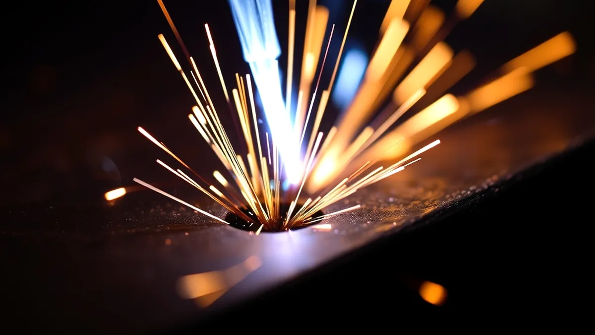
Before you can eliminate spatter, you have to be able to describe it precisely, because “spatter” gets blamed for about six different problems that each have their own cure. Some of what welders call spatter is actually transfer-mode instability. Some of it is boil-over from a contaminated puddle. Some of it is flux and slag being expelled by gas trapped in the wire. Naming the enemy correctly is half the battle.
Definition of Welding Spatter
Welding spatter refers to the tiny droplets of molten material that are expelled during the welding process. These droplets do not contribute to the weld bead formation and instead adhere to the base material or the surrounding area. In flux core welding, spatter can create added work in post-weld cleanup, potentially damaging the workpiece or surrounding materials.
Spatter droplets range from fine specks you can barely see to BB-sized spheres that leave dents. They leave the arc at high velocity, which is why they embed themselves in adjacent steel rather than just resting on top of it. That is the part that hurts: once a droplet cools and fuses to a surface you intended to paint or powder coat, removing it means abrasion, and abrasion means more rework.
Spatter is also a process diagnostic. Every welder I know uses the arc’s behavior as a feedback loop, and the type of spatter tells you what went wrong. Fine, even popping across the whole bead usually points to parameters. Big, irregular chunks with a wandering arc point to feeding or contact tip problems. A shower of dark, crusty particles mixed with smoke often means moisture or contamination. Learn to read the mess and you will know what to adjust before you strike the next arc.
Why Spatter Occurs With Flux Core Welding
Several factors contribute to the occurrence of spatter in flux core welding, and the four most common culprits are the ones you can control from the driver’s seat of the machine:
- Voltage and Amperage Settings: If the settings are too high or too low for the task, this imbalance can cause excessive spatter. Low voltage makes the arc stub and pop as the wire crashes into the puddle; too much voltage makes the arc long, broad, and sloppy, throwing molten droplets sideways.
- Wire Feed Speed: Similar to voltage and amperage, an incorrect wire feed speed can lead to instability in the arc and increased spatter. Wire feed speed sets your amperage, so if it is wrong, your heat input is wrong, and the arc spends its time fighting the puddle instead of wetting into it.
- Poor Contact Tip Condition: A worn-out or incorrectly sized contact tip can disrupt the electrical current and cause spatter. An elongated or off-size bore throws the wire off center, so it enters the arc at an angle and swings the arc with it.
- Incorrect Stick-Out Length: Too much or too little distance between the contact tip and the workpiece can cause arc instability. Stick-out changes your actual voltage, your inductance, and your preheat — so it silently rewrites the settings you carefully dialed in.
Identifying and adjusting these variables are critical steps in reducing spatter and enhancing the overall efficiency of your flux core welding projects. Add four more that show up constantly in the field — dirty base metal, wrong polarity, wind disrupting the shield, and worn drive rolls feeding the wire in pulses rather than a steady stream — and you have covered roughly nine out of ten spatter complaints.
The Physics: Short-Circuit Transfer and Why Flux Core Pops
Most hobby and light-industrial flux core welding runs in short-circuit transfer mode. The wire feeds into the puddle, touches it, shorts out, melts off at the point of contact, the arc re-strikes, and the cycle repeats dozens to hundreds of times per second. It is a violent little event, repeated constantly, and the physics of that cycle is exactly where spatter is born.
Government research summarized in a National Institute of Standards and Technology study on metal transfer describes the mechanism plainly: during a short circuit, current rises sharply at low voltage, ohmic heating melts the wire, and the liquid column that forms is inherently unstable. When it separates, the arc is re-established — and the authors note that “this cyclic extinction of the arc may lead to severe spatter.” The more chaotic that cycle, the more metal gets thrown. You can read the full study, published through govinfo, the U.S. Government Publishing Office’s repository, if you want the oscilloscope-level details.
Field note: Think of each short circuit as a tiny explosion you are trying to keep small. Voltage that is too low makes the wire bury itself in the puddle before it can melt off, so each short dumps more energy in one place. Voltage that is too high stretches the arc so the wire melts off in free space, away from the puddle, and the droplet flies somewhere useful — nowhere. Your job is to land in the narrow band where the wire melts off right at the surface of the pool.
The American Welding Society’s Welding Digest breaks the process down in accessible terms in its article Flux Core Arc Welding (FCAW): What It Is, How It Works, and How to Fix Common Issues, and makes a useful comparison for anyone who also MIGs: gas metal arc welding generally produces less spatter and less post-weld cleanup, while flux core trades some of that cleanliness for wind tolerance, dirty-metal tolerance, and penetration. It is a trade you accept knowingly, not one you have to suffer through.
What Spatter Really Costs You
It is tempting to treat spatter as a cosmetic annoyance, but the bill arrives in several different envelopes:
- Time. Every minute spent chipping, grinding, and wiping spatter is a minute not spent welding. On repetitive production work, cleanup can rival the actual welding time.
- Consumables. Spatter build-up chews through contact tips, nozzles, and liners faster, and the grinding discs used to remove it are a recurring expense that never shows up in a spool’s price.
- Rejection and rework. On anything with a visible surface — furniture, railings, automotive panels — spatter means part handling, re-cleaning, and sometimes starting over.
- Safety. Spatter is molten metal leaving the arc at speed. OSHA’s guidance on welding, cutting, and brazing hazards and solutions is blunt about the need for eye and skin protection, fire control, and ventilation, because the same particles that ruin a finish will also burn skin and eyes.
Reducing spatter is therefore not vanity. It is throughput, cost control, and safety wearing a cosmetic disguise.
Pre-Welding Setup for Spatter Reduction

Pre-welding setup for spatter reduction is pivotal in achieving clean welds with minimal post-weld cleanup. Experienced welders know that taking the time to prepare correctly can make all the difference. The following steps can significantly reduce spatter during flux core welding, leading to more efficient projects and higher-quality results.
Importance of Proper Machine Setup
Ensuring your welding machine is correctly set up is the first step in minimizing spatter. A well-calibrated machine contributes to stable arcs and smoother welding. Begin by checking the manufacturer’s guidelines for setup and confirm that all connections are secure. It is essential to verify equipment functionality, especially the condition of the torch and cable, to prevent any unexpected issues that might increase spatter.
- Check the electrical circuit. Tighten the work clamp connection, gun-to-machine connection, and ground. A loose or corroded connection adds resistance, which shows up as an erratic arc and unpredictable spatter.
- Inspect the gun liner and cable. Kinked, crushed, or contamination-filled liners cause the wire to feed in pulses. Feed should feel smooth when you pull wire through with the tip removed.
- Fit the correct contact tip. Match the bore to the wire diameter exactly, and screw it snugly into the diffuser. A loose tip arcs internally; a worn tip throws the wire off axis.
- Set drive roll tension. Knurled rolls for flux core, adjusted just tight enough that the wire does not slip or deform. If the rolls are marking or flattening the wire, back them off.
- Confirm polarity. The single most overlooked setup step. Wrong polarity will produce a spattery, hard-to-control arc no matter how good your other settings are — more on this shortly.
- Set gas flow if required. For gas-shielded flux core, 35–50 cubic feet per hour through a clean nozzle and diffuser; for self-shielded wire, no gas at all, and remove the gas nozzle so you can actually see the puddle.
- Dial in your starting parameters. Use the manufacturer’s recommended starting point, then fine-tune on scrap of the same thickness you are about to weld.
Selecting the Right Parameters: Voltage and Wire Feed Speed
Adjusting the welding parameters is crucial for reducing spatter. Voltage and wire feed speed must be balanced based on material thickness and welding position. These two controls are inseparable: wire feed speed determines your amperage and therefore how much metal arrives per second, while voltage determines arc length and how that metal is distributed. Change one and you must re-check the other.
- Opt for lower voltage and wire feed speed for thinner materials to prevent burning through.
- Thicker materials require higher voltage and wire feed speed for adequate penetration.
- Out-of-position welding (vertical, overhead) wants lower heat than flat welding on the same thickness, so drop both settings and slow down.
It is vital to run a few test welds on scrap material to fine-tune these settings before you start on your actual workpiece. Two inches of scrap bead will teach you more than an hour of reading dials. If you want the deeper dive into how the two dials interact, our Flux Core Welding Settings Chart walks through the pairing in detail, and the Flux Core MIG Welding Wire Speed and Voltage Chart covers how to translate a machine’s numbered dial into actual numbers.
Settings Charts for Common Wire Sizes
Charts are starting points, not commandments — wire brand, machine response, and joint fit-up all shift the ideal. But a good starting point means you are fine-tuning instead of guessing, and fine-tuning is where spatter disappears. The table below gives typical open-root and butt-joint starting parameters for self-shielded flux core wire on mild steel, using a drag technique and roughly 3/4-inch stick-out.
| Wire Diameter |
Material Thickness |
Wire Feed Speed (ipm) |
Arc Voltage |
Approx. Amperage |
| .030″ (0.8 mm) |
16 ga – 1/8″ |
180–260 |
17–19 V |
70–110 A |
| .030″ (0.8 mm) |
1/8″ – 3/16″ |
260–350 |
19–21 V |
110–140 A |
| .035″ (0.9 mm) |
14 ga – 1/8″ |
200–300 |
18–20 V |
90–120 A |
| .035″ (0.9 mm) |
1/8″ – 1/4″ |
300–400 |
20–22 V |
120–160 A |
| 1/16″ (1.6 mm) |
1/4″ – 3/8″ |
300–450 |
22–25 V |
160–210 A |
| 1/16″ (1.6 mm) |
3/8″ – 1/2″ |
450–600 |
25–28 V |
210–290 A |
Read the chart vertically first: find your wire, then your thickness, then take the middle of the range as your starting point. From there, apply two simple adjustments. If the bead is tall, narrow, and popping, nudge voltage up in half-volt steps. If the bead is flat, wide, and washing over the edges, nudge it down. For the specifics of the two most common light-wire sizes, our .030 vs .035 Flux Core Wire comparison explains which one feeds better on small machines and which one handles thicker plate. And when you step up to heavy wire, the 1/16 Flux Core Wire Settings guide covers the voltage, wire speed, and stick-out ranges that larger-diameter wire demands.
One more thing about machines: on many 120-volt welders the voltage control is a tapped range rather than an infinitely variable dial, which means you may have to solve spatter by moving wire feed speed instead. Raise the wire feed speed and arc voltage follows it down slightly; lower the wire feed speed and the voltage climbs. That relationship matters more than it sounds — it is the reason you can “chase” spatter by adjusting the wrong control and never catch it.
Importance of Clean Material Surface
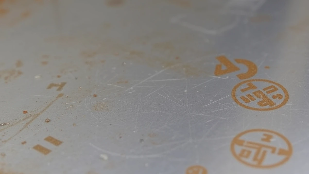
A clean surface is non-negotiable for reducing spatter. Any contaminants, such as rust, paint, mill scale, oil, or grease, can create irregularities in the arc, leading to increased spatter. Contaminants boil and gas out at arc temperature, and those gases have to go somewhere — usually straight through the puddle as pops and droplets.
- Use a wire brush, flap disc, or grinder to remove rust and scale back to bright metal on both sides of the joint.
- Clean the area with a solvent to eliminate oil or residue, then let it flash off completely before striking an arc.
- Ensure the workpiece is completely dry before welding — surface moisture and damp flux are hydrogen sources that cause both porosity and spatter.
- Wipe the joint a final time just before welding if the part has been sitting; even handling with dirty gloves re-contaminates the surface.
This surface preparation ensures a stable arc and a significant reduction in spatter. It also happens to be the cheapest fix on this entire list — a two-dollar wire brush prevents more spatter than a two-hundred-dollar machine upgrade.
A Pre-Weld Spatter Audit in Seven Steps
Build this into a habit and you will catch about 80 percent of spatter problems before they exist:
- Confirm the plate is clean, dry, and free of coatings in the weld zone.
- Confirm polarity matches the wire — electrode negative for most self-shielded wire, electrode positive for most gas-shielded wire.
- Confirm the contact tip bore matches the wire diameter and is not worn oval.
- Confirm stick-out is set to the recommended length and will stay consistent as the gun moves.
- Confirm drive roll type, tension, and liner condition feed the wire smoothly with no surging.
- Confirm voltage and wire feed speed against the starting chart for that wire, thickness, and position.
- Confirm the environment — no drafts across the arc, no moisture, adequate ventilation for fumes.
It takes about ninety seconds. It also saves you from the far more expensive ritual of grinding your own mistakes off a finished part.
Polarity and Shielding Gas: The Hidden Spatter Variables
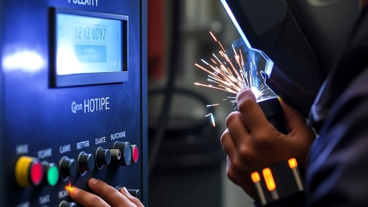
If you fix nothing else after reading this article, fix your polarity. Wrong polarity is the cause of more “impossible” flux core spatter problems than any other single factor, and it is invisible unless you physically check the studs inside the machine. A welder will spend an hour changing voltage trying to cure an arc that was never going to behave, when the actual problem was that the leads were connected for MIG wire instead of flux core wire.
DCEP or DCEN? Match Polarity to the Wire
Miller Electric’s setup guidance for flux-cored welding is unambiguous: self-shielded flux-cored welding requires DC electrode negative — straight polarity — with the connections usually found inside the machine near the drive rolls. That single instruction eliminates the most common cause of a rough, spattery arc on gasless wire. Gas-shielded flux-cored wire, by contrast, is typically run on DCEP (electrode positive, reverse polarity), which is also what solid MIG wire uses. When in doubt, the wire box and the machine’s labeling both say it outright, and checking takes ten seconds.
Here is why polarity changes spatter so dramatically: polarity controls where the heat goes. On DCEN, roughly two-thirds of the arc heat is concentrated at the electrode, which melts the wire quickly, keeps the arc relatively cool at the plate, and suits the flux-driven chemistry of self-shielded wire. On DCEP, heat concentrates at the workpiece, driving deeper penetration — which is exactly what gas-shielded flux core wants when it is combining an external gas shield with a flux core. Run the wrong one and the melting balance shifts: the wire either melts off too early and sprays droplets, or melts too late and stubs into the puddle. Both ends of that spectrum produce spatter.
Quick diagnostic: If your self-shielded wire gives you a crisp, crackling arc like frying bacon and a flat bead, polarity is probably right. If the arc sounds soft and mushy, the bead is tall and ropey, and spatter is fine and heavy, check polarity first — then voltage.
There is also a third polarity to know about: some gas-shielded flux-core procedures are specified as DCEP/DCEN depending on the classification, and a few dual-shield wires run on electrode positive while certain self-shielded wires run on electrode negative with rare exceptions. AWS classification designations exist precisely to standardize this, and the American Welding Society’s Welding Digest article Flux Cored Arc Welding: Principles, Uses and Challenges walks through how the two process variants differ in shielding, deposition, and cleanliness. The rule of thumb remains: read the wire’s specification sheet and follow it exactly.
Self-Shielded vs. Gas-Shielded: Two Processes, Two Spatter Profiles
Flux core is not one process — it is two, and they behave differently enough that mixing up their setups is another classic spatter trap. The table below lines them up side by side.
| Characteristic |
Self-Shielded (FCAW-S) |
Gas-Shielded (FCAW-G) |
| Shielding source |
Flux in the wire generates its own gas and slag |
Flux core plus an external bottle (75% Ar/25% CO2 or 100% CO2) |
| Typical polarity |
DC electrode negative (straight) |
DC electrode positive (reverse) |
| Wind tolerance |
High — designed for outdoor and field work |
Low — the gas shield blows away easily |
| Spatter level |
Higher; more visible popping |
Lower when correctly set |
| Slag and cleanup |
Heavy slag layer to chip and brush |
Lighter slag, easier cleanup |
| Best use |
Outdoor, windy, dirty or rusty steel, structural work |
Shop fabrication, cleaner beads, thinner material control |
| Drive rolls |
Knurled, to bite the softer tubular wire |
Knurled as well; never smooth V-groove on cored wire |
The spatter difference comes down to shielding efficiency. When the gas shield is complete and stable, the arc burns quietly and the droplets transfer smoothly. Interrupt that shield — with wind, with a clogged diffuser, with the wrong gas — and atmospheric nitrogen and oxygen get into the arc, destabilize it, and blow the puddle apart. This is why gas-shielded flux core welds so much more quietly indoors and why the same wire, taken outside on a breezy day, can turn into a fireworks display.
Gas Selection, Flow, and Delivery
For gas-shielded flux core, gas choice is a spatter decision as much as a metallurgical one:
- 100% CO2 runs hotter, penetrates deeply, and is cheap, but produces more spatter and a rougher bead than argon blends.
- 75% argon / 25% CO2 (C25) gives a smoother, quieter arc with noticeably less spatter and better bead appearance, at a higher gas cost.
- Argon-rich blends with oxygen or CO2 are common in industrial dual-shield procedures for stable spray-like transfer and low spatter at high deposition rates.
Whatever the blend, delivery matters. Set flow to the wire manufacturer’s specification (commonly 35–50 cfh), check the regulator gauge before every session, and always test with a flowmeter or the “dunk the nozzle in water” trick after any gas-line change. Air leaks, kinked hoses, and a cracked insulator all bleed gas, and a starved shield will cause both porosity and spatter no matter how perfect your technique is.
Choosing Quality Materials and Equipment
Ensuring a clean, spatter-free weld using flux core welding hinges heavily on the choice of materials and equipment. High-quality materials lead to fewer welding issues, reduced cleanup, and a stronger bond. The selection process is crucial for novice and experienced welders aiming for professional results.
Impact of Wire Quality on Spatter
The caliber of wire used in flux core welding plays a vital role in the amount of spatter produced. A higher quality wire might cost steeply, but the benefits outweigh the initial cost. Good wires ensure consistent feeding, excellent conductivity, and minimal impurities, leading to a cleaner weld. To identify a superior wire:
- Check for smooth, consistent wire with no irregularities along its length.
- Look for well-packaged wire to prevent contamination from moisture and dust.
- Confirm that the wire specification (AWS classification, diameter, polarity) matches your welding requirements.
- Inspect the spool itself: neatly wound, evenly layered wire unspools without snags.
High-quality wire will help maintain a stable arc, directly reducing the tendency for spatter. Cheap wire is often the false economy of the welding world — it saves a few dollars at checkout and costs you an hour of grinding, plus the tips and liners it destroys along the way. Our guide to the Best Flux Core Wire breaks down which spools consistently deliver smooth arcs and which ones to leave on the shelf.
Cast, Coil, and Spool Condition
Even premium wire can misbehave if its mechanical condition is poor. Wire leaves the spool with a natural curve called its cast (the radius of the curve in the wire) and a secondary bend called hook or coil. Inside the gun, the wire is straightened once as it passes through the liner and again at the contact tip. If the cast is wrong for your liner, or the wire has been kinked, crushed, or unraveled loosely across the shop floor, it retains memory and feeds in surges. Surge feeding means intermittent contact resistance at the tip, which means arc flicker, which means spatter.
- Never let a spool uncoil onto the floor — a single kink will plague you for the rest of the spool.
- Mount the spool so it brakes properly and does not free-spin after you release the trigger; overrun tangles the wire under the tray.
- Store wire indoors in its original packaging. Surface rust on flux core wire is a direct cause of feeding problems and arc instability — Lincoln Electric’s troubleshooting literature lists “electrode wire may be rusty or dirty” among the first checks for irregular arc behavior.
- Discard the last few feet of any spool that has picked up oil, coolant, or grinding dust.
Significance of the Right Welding Gun and Nozzle
The appropriate welding gun and nozzle selection is just as critical as the wire. A well-suited welding gun creates a more stable arc and has an ergonomic grip to enhance control during welding. Such features lead to less spattering. Look for:
- A gun that is compatible with your welder and work application — a 200-amp gun on a 400-amp duty cycle job will overheat, and an oversized gun is fatiguing on small work.
- One that supports smooth wire feed with the least resistance: straight cable routing, a good liner, and quality drive rolls.
- A device that handles the thermal demands of your specific projects, with a duty cycle rating that matches your actual arc time.
Similarly, the proper nozzle affects the gas flow dynamics, influencing spatter levels. A clean nozzle of the correct size will properly shield the weld, minimize oxidation, and reduce spatter. Bigger is not automatically better: an oversized nozzle streams gas past the arc in turbulent patterns, while an undersized nozzle chokes flow and can trap spatter against the diffuser. Match nozzle bore to the joint — a smaller nozzle for tight corners, a larger one for flat-out heavy work — and keep it clean. Ensure regular cleaning and maintenance of your nozzle to keep it in optimal condition.
Your choice of materials and equipment signifies your commitment to quality in flux core welding. A thoughtful selection equips you with the tools necessary for superior welding performance with minimal spatter.
Stick-Out and Contact Tip-to-Work Distance
Stick-out — technically contact tip-to-work distance, or CTWD — is the most powerful adjustment most welders never think to make. It is also the one variable that silently changes your voltage while the dial on the machine stays exactly where you set it. If your settings seem right but your arc behaves as if they are wrong, measure your stick-out.
What Stick-Out Does to the Arc
The wire between the contact tip and the workpiece is a length of electrical resistance and inductance. Lengthen it and you add resistance, which raises the actual arc voltage for a given dial setting; shorten it and the opposite happens. Lincoln Electric’s operating manuals state the relationship directly: lengthening the contact tip-to-work distance raises the voltage, shortening it lowers the voltage. Stick-out also preheats the wire — longer stick-out means more resistive preheat, softer wire entering the arc, and a different melting rate. Your wire feed speed, in other words, stops meaning what you thought it meant.
Because flux core wire is a hollow tube rather than a solid rod, it needs more stick-out than MIG wire to generate enough resistive heat to burn the flux correctly. Too short a stick-out with flux core is a classic beginner mistake: the arc is confined and violent, the puddle boils, and spatter is heavy. Too long and the wire feeds into the arc from so far away that it wanders, and the shielding from the flux’s own gas has not fully developed before the arc hits the plate.
Recommended Stick-Out Ranges
| Process |
Recommended Stick-Out |
If Too Short |
If Too Long |
| Self-shielded flux core |
3/4″ typical (3/8″–1″ workable) |
Violent arc, excessive spatter, poor visibility |
Unstable arc, worm tracks, lack of shielding |
| Gas-shielded flux core |
1/2″–3/4″ |
Spatter build-up on the tip, nozzle burn-back |
Gas coverage loss, porosity, wandering arc |
| Solid wire short-circuit MIG |
3/8″ (for comparison) |
Stubbing, spatter, tip burn-back |
Cold lap, porosity, arc wander |
Consistency matters as much as the absolute number. Our original guidance put the sweet spot at a stick-out typically between 3/8 inch and 3/4 inch for most applications, with the emphasis on keeping it consistent: a uniform stick-out maintains a stable arc, and any tendency for the length to wander across the joint translates directly into a wandering arc. Adjusting the wire feed speed to match the stick-out length is equally important, as it affects the burn-off rate of the wire and prevents excess molten droplets from splattering around. Aim the gun so the contact tip stays a fixed distance from the puddle as you travel, rather than letting the stick-out grow as you move along the seam.
Rule of thumb: if you find yourself steadily increasing the voltage dial to get the same arc you had at the start of a weld, your stick-out is probably growing as you travel. Reset your hand position before you reach for the dial.
Mastery of Flux Core Welding Techniques
Flux core welding is notorious for its convenience and ease of use, particularly in outdoor applications. Yet one challenge frequently arises: spatter — the shower of hot, molten metal particles that can mar the workpiece surface. Mastering flux core welding techniques is essential for minimizing spatter and ensuring a cleaner, more efficient welding process. Honing your skills in various welding techniques can significantly reduce the cleanup required, saving time and material in the long run.
Correct Welding Angles and Travel Speed
Welding angles and travel speed, when optimized, play a significant part in spatter control. Gun angle determines where the arc force points, and the arc force is what physically pushes molten metal out of the puddle. Point it wrong and you are plowing metal out of the joint on purpose.
| Parameter |
Recommended Range |
Effect on Spatter |
| Work angle |
5 to 15 degrees from the joint |
Reduces spatter by giving the wire a clear, centered path into the joint |
| Travel angle |
Drag, roughly perpendicular (5–15 degrees back) |
Minimizes spatter by preventing excessive arc force from blowing metal forward |
| Angle beyond 20–25 degrees |
Avoid |
More spatter, less penetration, general arc instability |
Travel speed influences the heat input and the size of the weld puddle. A controlled and consistent rate ensures even heat distribution, reducing the likelihood of spatter. Find a balance where the speed is neither too slow (causing excess buildup and spatter) nor too fast (leading to insufficient weld penetration). Too slow means you are sitting in a growing puddle, boiling it past its capacity; too fast means the wire outruns the pool and stabs into solid metal. Both ends of that range throw metal.
Push or Drag? The Slag Rule
With flux core welding, you should almost always drag (pull) — point the gun back at the finished weld and pull it away from the bead, so the arc is always acting on clean, preheated metal and the slag trails behind the arc instead of running in front of it. Miller Welds gives the memorable version of the rule: “If there’s slag, you drag.” Pushing flux core drives the arc over its own molten slag, which traps gas, causes pops, and throws spatter. The exception cases are specific — some out-of-position or tightly controlled procedures call for a slight push — so when the wire manufacturer’s sheet specifies something different, follow the sheet.
Techniques for Steady Welding
Techniques to maintain a steady welding process include:
- Supporting the welding hand: steady the welding hand with comfortable support, allowing precise control over the welding gun. Brace your wrist or forearm on the fixture, use a hood prop, or weld off-hand with your free hand in your pocket for stability.
- Smooth EAD (Electrode Arc Distance): keep the EAD consistent throughout the weld to prevent fluctuations in the arc. Consistent arc length is consistent voltage, and consistent voltage is a consistent puddle.
- Continuous movement: avoid lingering in one spot; move steadily along the weld seam. Dwell time is the enemy — the puddle grows, gets too hot, and starts throwing metal.
Additionally, practice a controlled technique such as the whip-and-pause or weave to manage heat input and the molten pool better, substantially reducing spatter. Whip-and-pause — advancing the arc slightly ahead of the puddle and stepping back into it — gives the leading edge of the weld time to solidify while keeping the pool from getting deep, which is invaluable on thin wall tube and open roots. A small, tight weave keeps the puddle moving and spreads heat evenly on wider joints; a wide weave does the opposite, overheating the center and pushing metal to the edges. Both techniques only reduce spatter when the underlying settings are right — technique trims the last ten percent, it does not rescue a bad setup.
If you are still building confidence with the fundamentals, our step-by-step walkthrough on how to weld with a flux core wire feed welder covers stance, hand position, and first-bead drills in more depth.
Travel Speed Drills That Build Muscle Memory
- The line drill: strike an arc on flat scrap and travel along a marker line at a steady pace for six inches. No stopping, no lifting. Check the bead for uniform width — width variation is speed variation.
- The stopwatch drill: time how long a bead takes and try to repeat it within half a second on the next pass. Consistency in time equals consistency in heat input.
- The angle check: have a partner watch your gun angle from the side for a full pass. You will be surprised how far it drifts from where you think it is.
- The thickness transition: run beads across a butt joint of two different thicknesses and practice shifting speed without stopping — a real-world skill that also teaches heat control.
Optimal Welding Environment
The success of flux core welding largely hinges on preparing the welding environment. Achieving a clean, spatter-free weld requires more than skill alone; the surroundings in which a welder works significantly impact the quality and efficiency of the task at hand.
Effects of External Elements on Spatter
Undesired spattering during the welding process often stems from interactions with external elements. Recognizing these factors enables welders to hone in on a pristine, controlled welding atmosphere.
- Wind: even the slightest breeze can cool the weld pool too quickly, leading to a poor-quality weld with high spatter. Drafts from open bay doors, fans, and air conditioning also strip the shielding gas away before it can do its job.
- Humidity: moisture from the air can introduce hydrogen into the weld, which may cause porosity and excessive spattering. Damp flux or a wet plate is even worse — both are direct hydrogen sources.
- Temperature: extreme temperatures negatively impact the welding process, whether hot or cold, by disturbing the metal’s state. Very cold plate draws heat out of the puddle so fast that the arc has to work harder, while preheated or sun-baked plate changes penetration behavior.
Dust and airborne grinding compound the problem: particles settle on the wire, the plate, and inside the contact tip, all of which show up as arc instability. The American Welding Society’s overview of the process makes the same point in its discussion of where FCAW performs best — the environment is part of the procedure specification, not an afterthought.
Creating an Ideal Welding Environment
Certain conditions must be met to forge a setting conducive to optimal flux core welding. Control over these elements is crucial for a reduction in spatter and a boost in overall welding performance:
| Condition |
Control Method |
Why It Cuts Spatter |
| Shielding from drafts |
Use barriers or welding booths to protect the weld area from drafts and wind |
Keeps the gas or flux-generated shield intact around the arc |
| Moisture control |
Keep the area dry; consider dehumidifiers if needed to reduce air humidity |
Prevents hydrogen pickup, porosity, and puddle boiling |
| Ambient temperature |
Maintain a moderate temperature to prevent excessive cooling or heating of the weld zone |
Stabilizes puddle fluidity and burn-off rate |
| Airborne dust |
Separate grinding and welding areas; sweep rather than blow off plates |
Keeps contaminants out of the contact tip and puddle |
By implementing strategic temperature control, working in a clean, well-ventilated yet draft-free space, and ensuring the air is as free from contamination as possible, welders can drastically diminish the incidence of spatter and enhance their overall workflow. An ideal environment doesn’t occur by chance — it’s a well-planned and actively maintained foundation for superior welding practices.
Welding Outdoors: Wind, Drafts, and Self-Shielded Wire
The reason flux core exists at all is outdoor capability — but “wind tolerant” is not “windproof.” Self-shielded wire generates its own protective atmosphere from the flux, yet a steady breeze of even a few miles per hour will push that atmosphere off the puddle. Once shielding is lost, the arc becomes erratic and spatter increases immediately. Practical defenses:
- Position yourself, the work, and any available cover so the prevailing breeze does not cross the arc.
- Set up a windbreak — a sheet of plywood, a welding curtain, even a parked vehicle — a few feet upwind of the joint.
- For gas-shielded flux core outside, either move indoors or abandon gas and switch to a self-shielded wire rated for the job.
- Watch the puddle: if it suddenly goes from quiet to popping with no change in your settings, something in the environment just changed.
When outdoor structural work is on the menu, our related guide on stick vs. flux core welding compares how each process holds up against wind, dirt, and position when you cannot control the conditions.
Addressing Common Flux Core Issues
Flux core welding is a widespread technique due to its versatility and ability to produce strong welds even in windy conditions. However, even the most skilled welders can face challenges such as excessive spatter, which affects weld quality and increases cleanup time. You can reduce spatter and improve the welding process by addressing common flux core welding issues effectively.
Troubleshooting Wire Feeding Problems
One of the key culprits behind excessive spatter in flux core welding is poor wire feeding. Consistent and smooth wire feed is essential for a stable arc and reduced spatter — the wire is, after all, half of the electrical circuit and the entire filler supply. When it arrives in pulses rather than a steady stream, the arc length pulses with it, and each pulse throws metal. Here is how to address wire-feeding issues in the order that saves the most time:
- Check the tension. Ensure your drive roll tension is not too tight or too loose. Adjust according to the manufacturer’s recommendations. Too loose and the rolls slip, feeding intermittently; too tight and they crush the tubular wire, deforming it so it drags in the liner. Set it just tight enough that pulling the gun cable does not make the wire slip.
- Inspect the liner. A dirty or worn liner can lead to irregular wire feeding. Clean or replace the liner if necessary. Flux core wire sheds fine flux dust as it flexes, so liners soil faster than you would expect — many manufacturers recommend cleaning or replacing the liner every 50 pounds of flux-cored wire, compared to about 300 pounds for solid wire.
- Use the right drive rolls. Match the drive rolls to the wire size and type. Cored wire needs knurled rolls that bite the soft tube without compressing it; using incorrect registrations or smooth V-groove rolls on flux core causes slippage or deformation of the wire.
- Monitor the wire spool. Ensure the wire spool is not obstructed and can unravel without resistance. Spool brakes that are too tight cause feed surge; too loose and the spool over-runs and tangles under the tray.
- Check the contact tip. Remove it and inspect the bore. If the wire wiggles noticeably side to side, the tip is worn and must be replaced — an oversized bore is a hidden source of spatter.
- Check the gun cable routing. Sharp bends, tight loops, and cable ties holding the gun in a stressed position all add friction. Route the cable with a gentle radius and hang the gun when not in use.
Miller Electric’s defect-troubleshooting guide lists rusty or contaminated wire, wrong-size or worn contact tips, and the wrong contact-tip-to-nozzle recess among the standard causes of excessive spatter — a useful reminder that feeding problems and spatter problems are frequently the same problem.
Mitigating External Factors
Beyond equipment settings, external factors also play a significant role in the occurrence of spatter. Address these external factors to enhance your flux core welding quality:
| Factor |
Corrective Action |
What Goes Wrong If Ignored |
| Welding speed |
Adjust the welding speed. Too slow causes excessive buildup, while too fast leads to a lack of fusion |
Slow: over-hot puddle that boils and spatters. Fast: wire stabbing into cold metal, stubbing and popping |
| Stick-out length |
Maintain a consistent stick-out length. Usually, a 3/8-inch to 1/2-inch stick-out works well for most applications |
Arc length drifts, actual voltage changes under the dial, bead width becomes inconsistent |
| Ambient wind |
Shield the welding area from the wind or use windbreaks to minimize its impact on the welding arc |
Shielding loss, arc wander, porosity, heavy spatter |
| Material cleanliness |
Clean the base material thoroughly to remove any contaminants, such as rust or paint, before welding |
Gas release from coatings, boil-over, spatter, porosity |
By tackling these issues head-on with a strategic and systematic approach, flux core welders can significantly reduce spatter and enhance the quality and efficiency of their welding projects. Consistency and precision are your allies in achieving the best welding results.
Symptom-to-Fix Spatter Troubleshooting Table
When spatter shows up mid-job, work down this table before touching anything else. It follows the same logic as manufacturer troubleshooting charts, and it resolves the majority of complaints in a single pass.
| Symptom |
Most Likely Cause |
Fastest Fix |
| Fine, even popping across the whole bead |
Voltage too low for the wire feed speed |
Raise voltage in 0.5 V steps until the crackle steadies |
| Heavy, irregular spatter with a wandering arc |
Worn contact tip, loose tip, or poor ground |
Replace the tip, tighten connections, move the clamp closer |
| Spatter only at the start of each weld |
Long initial stick-out, cold plate, slow arc start |
Set stick-out before striking; start on clean, preheated metal |
| Spatter with a mushy, soft-sounding arc |
Wrong polarity |
Check the leads; run DCEN for self-shielded, DCEP for gas-shielded |
| Burning back to the tip, spatter at the nozzle |
Stick-out too short, nozzle clogged, gas flow wrong |
Lengthen stick-out, clean nozzle and diffuser, verify flow |
| Spatter that starts suddenly outdoors |
Wind or draft destroying the shield |
Add a windbreak; reposition; check for open doors and fans |
| Spatter plus porosity and sugar on the bead |
Moisture, rusty wire, contaminated plate |
Dry the plate, replace the wire, re-clean the joint |
| Intermittent surging arc with feed noise |
Drive roll tension, liner, or spool brake |
Re-tension rolls, clean liner, free the spool |
Achieving Better Welds With Flux Core
Flux core welding is a popular choice for its versatility and speed. Still, it can often lead to the common problem of spatter, which affects the aesthetics of your welds and requires additional cleanup. Achieving better welds with flux core necessitates blending the proper techniques, equipment adjustments, and understanding of the welding process. With a few key strategies, you can significantly reduce spatter and ensure more robust, cleaner welds.
Importance of Practice and Skill Refinement
Just like any other art, welding demands diligent practice. Refining your skills with a flux core welder reduces the occurrence of spatter and enhances the overall strength and quality of your welds. A steady hand and precise control over the welding gun are essential. Here are the four disciplines to keep sharp:
- Stick-out length: maintain a consistent wire stick-out length, typically between 3/8 and 1/2 inches.
- Welding speed: adjust your speed; too fast can create poor fusion, whereas too slow might generate excess spatter.
- Angle of attack: keep the torch at a 10 to 15-degree angle from perpendicular to get the best results.
- Parameter settings: fine-tune the voltage and amperage on your welder to match your working material.
Practice deliberately rather than just repeatedly. Run a bead, chip the slag, look at it, and name what happened before running the next one. If you cannot say why the bead looks the way it does, another hundred passes will not teach you anything. Ten analyzed beads beat a hundred anonymous ones every time, and the scrap-metal cost of that habit is a few dollars.
Reading the Weld Pool and Making Adjustments
Observing the weld pool provides invaluable feedback on your technique and settings. Noticing how the weld pool forms and reacts during the process allows for on-the-fly adjustments that can improve the outcome and minimize spatter. Key points include:
- Size and shape: the weld pool should be consistent and symmetrical. Adjust travel speed if it is not.
- Weld penetration: deep enough penetration indicates good fusion. If it is lacking, increase the voltage or amperage.
- Surface appearance: a smooth surface means you are doing well. Rough surfaces are often a sign of excessive spatter and unstable transfer.
React quickly: the weld pool changes rapidly, and your ability to respond to these changes makes all the difference. If spatter increases, swiftly alter your angle or speed to correct the issue. Sound is your best early-warning system — a steady, crisp frying-bacon crackle means a stable short-circuit arc, while a soft, sputtering burble means something has drifted out of range. Learn to weld by ear as much as by sight, and you will catch spatter conditions before they leave the puddle.
Read the Bead After the Slag Comes Off
- Chip the slag while the bead is still warm — slag releases far easier and cracks in long ribbons rather than shattering into chips that embed in the plate.
- Wire brush and inspect for the three tells: convex (too cold or too fast), washed-out and wide (too hot or too slow), and crusted with fine droplets (unstable transfer — go back to settings).
- Check for undercut along the toes of the weld. Undercut plus spatter almost always means travel angle too steep or voltage too high for the speed.
- Log the settings that worked on the part. A notebook of proven settings for your machine, your wire, and your typical material is worth more than any chart.
Reducing Spatter Post-Weld
Spatter can be a persistent nuisance for welders, leading to extra cleanup and potential damage to the workpiece. Addressing this issue post-weld involves both preventative measures and effective cleanup strategies.
Importance of Anti-Spatter Products
Anti-spatter products are crucial in the battle against post-weld spatter. These specialized solutions form a protective barrier on the surface around the welding area, repelling spatter and making cleanup a breeze. The category is broader than most welders realize:
- Anti-spatter sprays are misted or brushed onto the plate, jig, or fixture around the weld zone. Spatter lands on the film rather than fusing to the steel, then wipes or washes off.
- Nozzle dip (anti-spatter gel) is a jelly-like paste you dip the hot nozzle into. It prevents spatter from sticking to the nozzle and diffuser and is one of the cheapest consumables with the highest return in the shop.
- Nozzle anti-spatter paste and cream are brushed onto the outside of the nozzle for longer-lasting protection between dips.
- Weld-through and spatter-release coatings are used on fixtures and clamps that see hundreds of welds a day.
The benefits of putting them to work are concrete:
- Protection for work surfaces: anti-spatter sprays safeguard the workpiece from being marred by spatter, maintaining the integrity of the metal.
- Increased productivity: by minimizing post-weld cleanup time, welders can focus more on the quality of their work rather than spatter management.
- Cost-effective: reducing spatter adhering to equipment reduces wear and tear, which lowers tool maintenance costs.
One caution: keep anti-spatter products off the weld joint itself. Anything organic burning in the arc creates fumes and contamination — a benefit on the fixture two inches away becomes a defect if it migrates into the puddle.
How to Remove Spatter That Is Already There
Sometimes spatter happens anyway. Removing it correctly matters — aggressive grinding removes base metal and creates more rework. Work from least invasive to most invasive:
- Chipping hammer or scraper. While the weld and plate are still warm, a light tap pops most droplets loose without touching the base metal.
- Wire brush or knotted wheel. Handles the fine speckle left behind after chipping and cleans the bead itself.
- Flap disc or grinding disc on a light touch. For droplets welded onto a visible surface, use the lightest abrasive that works and feather it so you do not leave a bright crater in the middle of a dark plate.
- File or spot drill for precision areas. Hinge holes, threads, and mating surfaces need targeted removal rather than blanket grinding.
- Solvent wipe as the final step. Removes fingerprints, cutting oil, and anti-spatter residue before paint or powder coat.
If you find yourself doing this for more than a few minutes per foot of weld, treat it as a process signal rather than an unavoidable chore. Something upstream — settings, cleanliness, shielding — is out of adjustment, and cleanup is where the bill for it arrives.
Cleaning and Maintenance Tips for Reduced Spatter
Keeping your welding equipment in top condition is essential for minimizing spatter. Follow these cleaning and maintenance tips:
| Task |
How Often |
Why It Reduces Spatter |
| Remove spatter from inside the gas nozzle |
Every 5–10 minutes of arc time, or as soon as build-up appears |
A clean nozzle ensures a steady, uninterrupted gas flow, critical in reducing spatter |
| Dip the nozzle in anti-spatter gel |
Every few passes |
Keeps droplets from fusing to the nozzle in the first place |
| Check and replace worn parts |
As required; inspect tips weekly |
Worn contact tips, liners, and other consumables significantly influence the occurrence of spatter |
| Clean or replace the gun liner |
About every 50 lb of flux-cored wire |
Smooth feeding keeps arc length — and actual voltage — constant |
| Clean the gas diffuser |
Every time the nozzle is cleaned |
A clogged diffuser channels gas unevenly and lets spatter into the stream |
| Maintain correct torch angle and stick-out |
Every weld |
Proper welding technique results in less spatter, allowing more control and precision during the weld |
| Check drive rolls and spool |
Weekly, or when feed feels uneven |
Knurled rolls in good condition feed steadily without crushing the wire |
Additionally, ensure all metal surfaces are clean and contaminant-free before welding. Remove rust, oil, and dirt using appropriate cleaning agents or grinders; this keeps the weld area pure and reduces the likelihood of spatter clinging to the post-weld surface. Lincoln Electric’s maintenance guidance makes the same point about consumables: keep the nozzle clear so gas flow is not inhibited, check the diffuser for clogging, and replace contact tips once the bore elongates, because a worn tip no longer places the wire where you aimed it.
Safety: Fumes, Ventilation, and Protection
No article about spatter would be complete without talking about what those particles are and what else comes off the arc with them. Spatter is the visible hazard; fume is the invisible one, and flux core generates more fume than almost any other semiautomatic process because the flux is burning to create its shield.
- Ventilation is a requirement, not a preference. OSHA’s construction standard 29 CFR 1926.353, Ventilation and Protection in Welding, Cutting and Heating, requires mechanical ventilation whenever welding takes place in a confined space and calls for local exhaust positioned close to the work so fumes are removed at the source.
- Know what you are breathing. NIOSH’s welding topic page on welding fumes and manganese notes that welding fumes are composed of metals and that exposure varies with the wire, flux, base metal, and whether the work is done in a confined space.
- Clean the plate first — it is a fume control too. OSHA’s fact sheet Controlling Hazardous Fume and Gases during Welding specifically advises cleaning welding surfaces of coatings and solvent residue that can generate toxic exposure.
- Protect against the spatter itself. Safety glasses under the helmet, jacket sleeves closed, no exposed skin, and no synthetic fabrics that melt. Spatter burns are the most common injury in every shop I have worked in, and they are entirely preventable with standard PPE.
Professional habit: treat fume control and spatter control as the same discipline. The cleanest, best-shielded, correctly parameterized arc produces the least of both — which is one more reason every technique in this article is worth learning properly.
The Ten-Minute Pre-Weld Routine That Eliminates Most Spatter
If you want one consolidated, repeatable routine to run before every job, this is the one we teach in our shop. It takes about ten minutes and addresses every major spatter source covered in this guide:
- Inspect the plate (2 minutes). Grind to bright metal, solvent wipe, dry completely.
- Verify the wire (1 minute). Right classification, right diameter, dry, no surface rust, spool mounted and braking correctly.
- Check the gun (2 minutes). Tip bore correct and unworn, liner clean, nozzle clear, diffuser free of build-up, cable routing with gentle bends.
- Verify polarity (30 seconds). DCEN for self-shielded, DCEP for gas-shielded unless the wire sheet says otherwise.
- Set parameters (1 minute). Starting values from the chart for your wire size and thickness, then one test bead on scrap.
- Set stick-out and angles (1 minute). 3/4-inch stick-out, 5–15 degree work angle, drag with a 5–15 degree travel angle.
- Check the environment (1 minute). Block drafts, confirm ventilation, clear the area of dust and moisture.
- Stage the cleanup tools (30 seconds). Chipping hammer, wire brush, and anti-spatter gel within arm’s reach — because the first ten seconds after the arc stops is when spatter comes off easiest.
Run that routine consistently and you will find that most “spatter problems” never appear at all. The welders who complain least about cleanup are not the ones with the best grinding technique — they are the ones who never created the mess.
Frequently Asked Questions About Reducing Spatter When Flux Core Welding
What Causes Spatter in Flux Core Welding?
Spatter during flux core welding typically results from high voltage settings, incorrect wire feed speed, or impurities in the material. Adjusting welder settings and preparing metal surfaces can significantly reduce spatter. In practice, the most common triggers are voltage and wire feed speed that are out of balance with each other, a worn or wrong-size contact tip, incorrect stick-out length, wrong polarity, inadequate shielding caused by wind or a clogged nozzle, and a plate contaminated with rust, oil, paint, or moisture. Work through them methodically — settings first, then consumables, then environment — and you will find the actual cause rather than guessing.
How Do You Choose the Suitable Flux Core Wire?
Selecting the suitable flux core wire depends on the welding job. Factors include the base metal type, welder compatibility, and required weld strength. Consult the welder’s guide or a professional for recommendations. Also weigh the application: self-shielded wire for outdoor and field work, gas-shielded wire for cleaner shop beads; a lighter diameter such as .030 or .035 for thin sheet and small machines, and 1/16-inch wire when you have the amperage to drive it into thick plate. The AWS classification printed on the spool — E71T-11 or E71T-14 for common self-shielded wires, E71T-1 for gas-shielded — tells you the polarity, positions, and shielding the wire was designed for, and following it exactly is one of the easiest ways to avoid spatter from the start.
Can Welding Technique Reduce Spatter?
Yes, proper welding technique is crucial in minimizing spatter. Techniques such as maintaining a steady travel speed and the correct angle can help ensure a cleaner welding process with less spatter. Drag rather than push with flux core wire, hold a consistent stick-out, support your hand so the arc length does not wander, keep the puddle moving instead of dwelling, and listen to the arc: a steady crackle tells you the short-circuit cycle is stable, and any change in sound is your cue to look at what changed. Technique cannot rescue completely wrong settings, but once the machine is in the right window, technique is what keeps the arc inside it.
What Is the Best Angle to Weld Flux Core?
For flux core welding, a 15-degree angle is typically advised. Keeping the gun at a slight angle allows for better penetration and less spatter due to more focused heat distribution. In more detail: hold a travel angle of about 5 to 15 degrees off perpendicular using a drag technique, with a work angle of 5 to 15 degrees centered in the joint. Angles beyond 20 to 25 degrees are where spatter, arc instability, and lost penetration start, because the arc force begins blowing molten metal sideways instead of into the joint.
Why Does My Flux Core Weld Pop and Spark so Much Outdoors?
Almost always shielding. Even self-shielded wire, which generates its own protective atmosphere, can be overwhelmed by a breeze that pushes the gas away from the puddle before it stabilizes. The arc then burns in air, nitrogen and oxygen get into the molten metal, and the result is exactly what you see: violent popping and a shower of spatter. Set up a windbreak, reposition so the draft does not cross the joint, and confirm your other settings are in range — wind is usually the last straw on top of an arc that was already marginal.
Should I Use Anti-Spatter Spray on the Weld Itself?
No. Anti-spatter products belong on the surrounding plate, fixtures, and tooling — never in the joint. Anything organic or silicone-based that burns inside the arc will contaminate the puddle, causing porosity and inclusions that are worse than the spatter you were trying to prevent. Apply it to the areas adjacent to the weld, wipe it up before painting, and keep the joint itself chemically clean.
Does Wire Feed Speed or Voltage Matter More for Spatter?
They matter together, because they are not independent. Wire feed speed sets your amperage and how much metal arrives; voltage sets arc length and how that metal is distributed. If the two are mismatched, no amount of adjusting the other will fix it: low voltage with high feed speed causes stubbing and violent short circuits, while high voltage with low feed speed creates a long, wild arc that throws droplets. Start from a manufacturer’s matched pair for your wire and thickness, run a test bead, then adjust one control at a time in small increments.
How Much Stick-Out Should I Use With Flux Core Wire?
For most self-shielded flux core work, around 3/4 inch is the standard recommendation — roughly twice what solid wire MIG welding uses — with 3/8 inch to 3/4 inch covering the majority of real-world situations and manufacturer procedures allowing up to about 1 inch. Consistency matters more than the exact figure: hold it uniform across the whole weld, and remember that changing it also changes your effective arc voltage, so re-check your settings if your stick-out changes significantly.
Is Spatter Worse With Cheap Flux Core Wire?
Frequently, yes. Lower-cost wire is more likely to have inconsistent diameter, poor weld seam quality, surface rust from inadequate packaging, and flux that varies from inch to inch. All of those show up as arc instability and spatter, and they cost you far more in cleanup and ruined consumables than the spool saved. Buy wire from a known manufacturer, store it dry in its packaging, and inspect it before use — consistent feeding and a consistent arc are the two biggest spatter reducers a good spool gives you for free.
What Is the Fastest Way to Remove Spatter After Welding?
Remove it while the part is still warm. A light tap with a chipping hammer pops most droplets clean off the plate without abrasion, and a quick pass with a knotted wire brush finishes the fine speckle. Only reach for a flap disc on droplets that will not lift, and use the mildest abrasive that works so you do not gouge the base metal. Prevention beats removal every time: a thin film of anti-spatter spray on the surrounding plate, or anti-spatter gel on the nozzle, will save you more time than any removal technique.
Conclusion
Mastering flux core welding without excess spatter requires practice and attention to detail. The strategies discussed are your roadmap to cleaner welds — from understanding short-circuit transfer physics and matching polarity to your wire, through settings charts for .030, .035, and 1/16-inch wire, stick-out and gun angles, travel speed, clean material, quality wire, nozzle and diffuser maintenance, wind and moisture control, wire-feed troubleshooting, and the anti-spatter products that make the final cleanup almost effortless.
Implement them each time you weld. Start with the ten-minute pre-weld routine, run a test bead, listen to the arc, and adjust one variable at a time. With the right equipment, settings, and technique, your welds will be stronger and more aesthetically pleasing — and your grinder will spend most of its life on the shelf.
Aim for perfection, and remember, patience is vital to reducing spatter. Every hour you invest in setup and technique returns itself several times over in saved cleanup, saved consumables, and parts you are proud to hand over. The mess you prevent never has to be cleaned up at all — and that is the whole point.