Key Takeaways
- Drive rolls are the only parts that actually move the wire. Everything you see at the weld pool starts with two small wheels gripping the wire and pushing it through the gun, so feed problems almost always trace back to them.
- Flux-core wire is a soft tube, not a solid rod. It is a thin steel sheath filled with powdered flux, which means it can be crushed, flattened or kinked far more easily than solid MIG wire.
- Knurled rolls grip, V-groove rolls guide, U-groove rolls cradle. Knurled or knurled-V rolls are usually the everyday choice for self-shielded flux-core wire, while plain V-groove rolls suit hard solid wire.
- Match the groove to the wire diameter exactly. 0.030, 0.035, 0.045, 0.052 and 1/16 inch wire each want a roll cut for that size, and a mismatched groove is a hidden cause of slipping.
- Tension is a balancing act. Too tight flattens the tube and creates kinks; too loose lets the rolls spin without moving wire. Set it with a simple test instead of cranking it down.
- Feed problems rarely live in one place. Birdnesting, a stuttering arc and erratic wire speed usually come from a worn roll, a dirty liner, a mismatched contact tip or bad tension.
- Polarity matters for flux-core. Self-shielded wire runs DCEN and gas-shielded flux-core runs DCEP. Wrong polarity gives weak, spattery welds that no drive roll can fix.
- Rolls are wear items. Inspect them every time you change spools and replace them when you see shiny grooves, notches or flat spots rather than waiting for a failure.
The Morning a Fifteen-Dollar Part Held Up the Whole Job
Picture a Saturday on a friend’s property. The gate posts are set, the hinge brackets are cut, and the only task left is to weld them in place before the rain comes in. The welder is a simple wire-feed machine, the cart holds a spool of self-shielded flux-core wire, and everything looks ready. The trigger is pulled and nothing useful happens. The wire crawls forward, stops, crawls again, and then a small loop of wire pops out of the feeder and tangles around the drive roll housing. The operator loosens the tension, tries again, gets a few inches of wire, and tangles again.
After twenty minutes of frustration the gun is pulled apart and the real culprit shows up. The drive rolls are the wrong type for the wire. They are smooth V-groove rolls sized for solid wire, and the soft tubular flux-core wire is sliding inside them instead of being gripped. The groove is also cut for a slightly smaller diameter than the spool actually holds, so the wire sits high in the groove and skates. The fix costs less than a fast-food meal and takes four minutes: pop the latch, swap in a knurled-V roll marked for the correct diameter, set tension with a quick test, and the weld runs clean for the rest of the day.
This story plays out in garages, fabrication shops and repair yards every week, and it points at a truth that experienced welders learn early. The wire, the settings and the technique get all the attention, but the drive rolls are the small mechanical handshake between your hand and the arc. When they are right, you forget they exist. When they are wrong, nothing else you try really helps. You can turn the wire speed up and down, you can change contact tips, you can fight the gun angle, and the weld still looks like it was made by a machine that never quite made up its mind.
If you are new to flux-core work, start with the fundamentals in what is flux core welding, because the tubular construction of the wire explains almost every quirk you will meet at the feeder. From there, the differences between wire families are laid out in flux core wire types, and the feeder itself is covered step by step in wire feed welder. Once the big picture makes sense, the drive rolls become the easiest part of the whole system to understand and to get right.
This article walks through the whole subject in plain language: what drive rolls do, how to choose between knurled, V-groove and U-groove profiles, how to match rolls to wire sizes from 0.030 up to 1/16 inch, how to set tension so the wire is gripped without being damaged, how liners and contact tips fit into the feed path, the polarity reminder that trips up a lot of flux-core welders, and a full troubleshooting table you can work through when the wire misbehaves. There is also a maintenance schedule, an installation walkthrough, an FAQ, and a short conclusion that pulls the important points together.
What Drive Rolls Actually Do Inside a Wire Feeder
A wire feeder looks complicated from the outside, with knobs, gears and a motor, but the working part is almost embarrassingly simple. The spool sits on a spindle with a brake that keeps the wire from overrunning. A length of wire passes from the spool into the feeder assembly, where it is pinched between two rolls. One roll is powered by the motor. The second roll is an idler that presses against the first. When you pull the trigger, the motor turns, the rolls turn together, and the friction between the roll surfaces and the wire pushes the wire forward through the gun liner, out of the contact tip, and into the weld.
That is the whole idea. The rolls do not melt anything, they do not measure anything, and they do not know what settings you dialed in. They only do two things: grip and push. Every wire-feeding complaint you will ever have is a complaint about grip or push, and the drive rolls sit at the center of both.
The Grip-and-Push Cycle
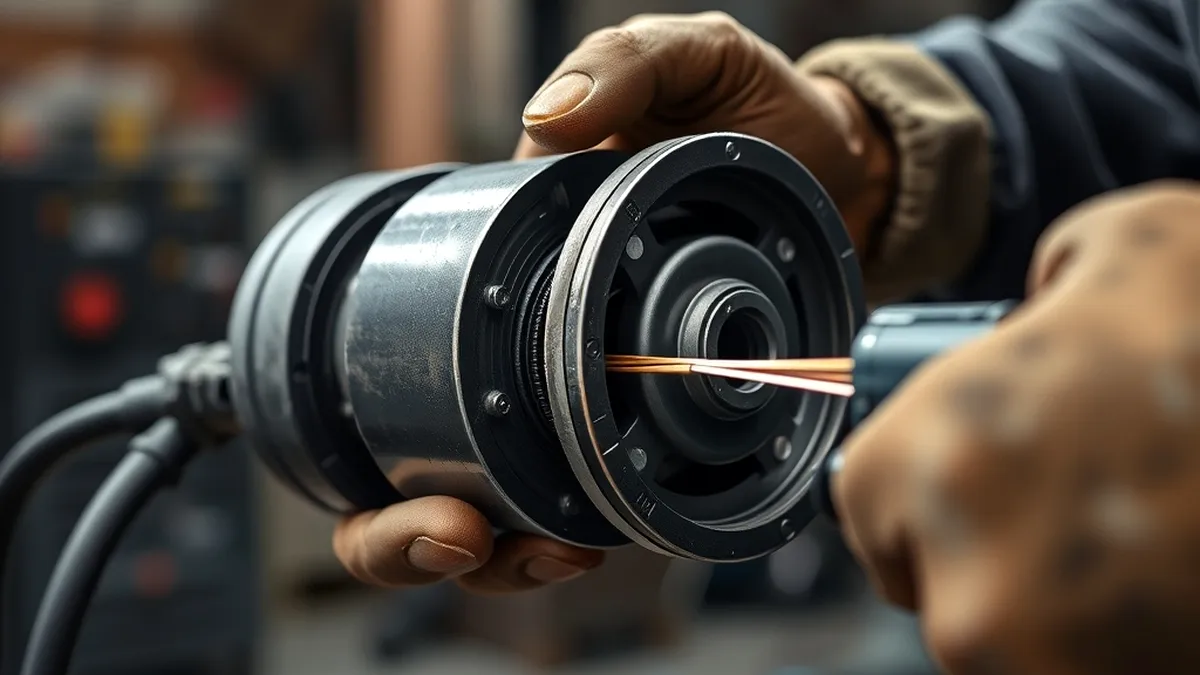
The grip comes from contact area. A perfectly smooth roll touching a perfectly smooth wire has very little purchase, so manufacturers cut patterns into the roll faces. Knurling raises small teeth that bite into the wire surface. A V-groove forces the wire down into a wedge so the sides of the groove carry the load. A U-groove lets the wire nestle into a rounded channel with more surface contact than a sharp wedge. Each approach trades grip against gentleness, and that trade is exactly what makes roll selection interesting when the wire is tubular.
The push comes from consistency. If the rolls grip the same way on every revolution, the wire moves at a steady rate and the arc stays stable. If the rolls grip on one spot and slip on the next, the wire speed pulses. At the weld pool that shows up as a rhythm of short arcs and long arcs, a bead that varies in width, and spatter that seems to come and go for no reason. Flux-core wire is less forgiving of this pulsing than solid wire because the arc has to keep melting the flux in the core along with the sheath, and an uneven supply of wire means an uneven supply of flux, which in turn means uneven shielding and inconsistent penetration.
Drive rolls also set the tone for the rest of the feed path. If they deliver wire smoothly, the liner and contact tip only have to guide it. If they deliver wire in pulses, the liner has to absorb the variation and the contact tip has to keep re-establishing electrical contact with a wire that keeps changing speed. Good rolls make every downstream part look good. Bad rolls make every downstream part look suspect, which is why troubleshooting should start at the feeder and work outward instead of starting at the gun.
Why Flux-Core Wire Behaves Differently
Solid MIG wire is a continuous drawn rod of steel, stainless or aluminum. It is stiff, uniform and hard to distort by hand. Flux-core wire is different in a way you can feel the moment you uncoil a length of it. Take a piece of 0.045 self-shielded wire and press it between your fingers and it gives slightly. Straighten a curve out of it and it wants to spring back in a soft, lazy way. That is the behavior of a tube, not a rod.
The tube construction is the whole point of the process, because the powdered flux inside is what produces the shielding gas and the protective slag when the arc burns it. The trade-off is mechanical. A tube has far less resistance to crushing than a solid bar of the same outside diameter. Squeeze it hard enough in one spot and it goes oval, then flat, then folded. An oval section will not pass cleanly through a contact tip bore sized for a round wire, and a folded section will snag in the liner. Even a small amount of ongoing deformation at the rolls creates a steady trickle of feed trouble.
There is a second consequence that people overlook. Flux-core wire has a lubricant and a light surface finish from the tube-making process, and it can be slightly less grippy than a clean solid wire. Combine a softer cross-section with a slicker surface and you have a wire that needs a roll pattern designed to bite without cutting. That is why knurled faces and knurled-V profiles show up so often on machines that run flux-core, and why a plain V-groove roll sized for hard wire can quietly ruin a day of welding. The wider process picture, including how the arc and the shielding work, is covered in flux core welder, and the practical knob settings live in flux core welding settings.
One more difference is size range. Self-shielded flux-core wire is most common in 0.030, 0.035, 0.045 and 0.052 inch, with 1/16 inch appearing on heavier structural and high-deposition work. Solid wire for light fabrication is most common in 0.023, 0.030 and 0.035. The overlap means many shops own both types of wire and, unless the rolls are swapped deliberately, one of the two wires is being fed by a roll that was never cut for it. This is the single most common root cause of feed trouble in mixed-use shops.
Finally, flux-core wires leave more residue. The flux powder sheds a fine dust as the wire passes through the feeder, and that dust works its way into the roll grooves, onto the idler arm pivot and around the tension nut. It builds up slowly, changes the effective groove shape, and eventually shows up as slippage that seems to appear out of nowhere. Clean rolls feed better rolls, and a quick wipe at every spool change is cheap insurance.
Knurled, V-Groove and U-Groove Rolls Explained
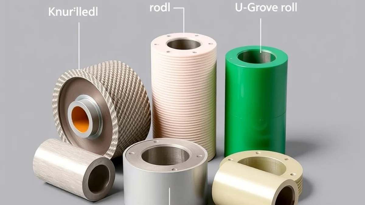
Roll profiles are the first decision you make and the one that matters most. Manufacturers describe them with a handful of names that overlap, so it helps to sort them into three families by shape: knurled faces, V-grooves and U-grooves. Some rolls combine two ideas, such as a V-groove with knurled walls, which is where the name knurled-V comes from. The right choice depends on what the wire needs, which is grip or gentleness, and how much of each it needs.
Knurled Rolls
A knurled roll has a pattern of small raised teeth cut into the groove face, similar to the knurl on a tool handle. When the rolls close on the wire, the teeth press tiny dimples into the wire surface and lock it in place. The grip is aggressive and immediate, which is exactly what you want when the wire is soft, slightly oily or otherwise inclined to slip.
Knurled rolls are the natural partner for self-shielded flux-core wire. The tubular wire is soft enough that the teeth can bite without flattening it, and the grip means the feeder can push the wire through a long liner, a bent gun or a cold morning without surging. Knurling also tolerates a bit of surface contamination better than a smooth groove, because the teeth cut through the film instead of sliding on it.
The downside is wear and marking. Knurled teeth are small, and over hundreds of hours they round off. As they round, grip drops, and the wire starts to slip at exactly the moment you are in the middle of a long seam. Knurled rolls can also leave a light pattern on soft aluminum wire, which is one reason aluminum usually runs on a different profile. The practical rule is simple: use knurled rolls when the wire is soft and needs help being pushed, and inspect them often because knurl wear is gradual and easy to miss.
V-Groove Rolls
A V-groove roll has a wedge-shaped channel. The wire sits down in the wedge and the two angled walls support it. Because the contact is along lines rather than over an area, a V-groove concentrates force on the wire surface, which makes it excellent for hard solid wire and poor for soft tubular wire.
On hard steel solid wire, a V-groove is hard to beat. The wire cannot be flattened by the wedge, the alignment is precise, and the feed rate stays accurate because the wire is held at a fixed depth in the groove. This is why many machines ship with V-groove rolls in the box. They are the right answer for the solid wire most buyers start with.
On flux-core wire, a plain V-groove is where trouble begins. The wedge focuses force on two lines across the tube wall, and a soft tube responds by going oval. An oval wire feeds fine for a while, then starts to stutter as the deformed section reaches the contact tip, then jams. If you have ever seen a flux-core wire emerge from a contact tip looking slightly flattened with a shiny stripe down one side, a V-groove roll was probably involved. There is a middle ground in the knurled-V roll, which adds teeth to the V walls so the wire is both supported and gripped, and that combination suits a wide range of flux-core diameters very well.
U-Groove and U-Knurled Rolls
A U-groove roll has a rounded channel instead of a wedge. The wire rests in a cradle and the force is spread around a larger arc of its circumference. Nothing digs in, nothing concentrates on a single line, and the tube keeps its round shape. U-grooves are the gentlest option and they shine on very soft wires, on thin-wall tube and on aluminum.
The trade-off is that gentleness reduces grip. On a hard wire a plain U-groove can allow surface slip, which shows up as an inconsistent feed. For flux-core wire the balance usually works well, especially on larger diameters where the tube wall is thick enough to feed reliably but soft enough to deserve a cradle. U-knurled rolls split the difference by adding a light knurl to the cradle, giving gentle support with a bit of bite.
The table below summarizes the everyday matching rules. It is a starting point, and your machine manual may refine it, but if you follow this chart you will avoid most of the feed problems that send people chasing their tails.
| Wire type and size |
Recommended roll profile |
Why it works |
Avoid |
| Self-shielded flux-core, 0.030 |
Knurled or knurled-V, sized 0.030 |
Soft thin-wall tube needs bite without crush |
Plain V-groove sized for solid wire |
| Self-shielded flux-core, 0.035 |
Knurled-V or U-knurled, sized 0.035 |
Best all-around grip for the most common flux-core size |
Oversized groove that lets the wire ride high |
| Self-shielded flux-core, 0.045 |
Knurled-V or U-groove, sized 0.045 |
Thicker wall tolerates more pressure, cradle keeps it round |
Worn knurl with visible polish marks |
| Self-shielded flux-core, 0.052 |
U-groove or U-knurled, sized 0.052 |
Heavy deposition wire, round shape must be preserved |
Rolls cut for 0.045 reused as a shortcut |
| Self-shielded flux-core, 1/16 |
U-groove or heavy knurled, sized 1/16 |
Large tube needs full support and real torque |
Light-duty rolls that slip under load |
| Gas-shielded flux-core, 0.030 to 0.045 |
Knurled or knurled-V, exact size match |
Tubular but often tighter wall, grip still helps |
Assuming gas-shielded equals solid wire handling |
| Solid steel MIG, 0.023 to 0.035 |
V-groove, exact size match |
Hard wire holds shape under wedge pressure |
Knurled rolls that dent and mar the surface |
| Solid stainless MIG, 0.030 to 0.045 |
V-groove or U-groove, exact size match |
Stainless is gummy and benefits from clean support |
Rolls used previously on carbon steel without cleaning |
| Solid aluminum MIG, 0.030 to 0.045 |
U-groove or knurled-V, large flat knurl |
Soft metal marks and dents under sharp wedges |
Standard V-groove that gouges the wire |
Two habits make this table work in real life. First, read the stamp on the roll face before every spool change and confirm it matches both the diameter and the wire family. Second, keep the rolls that came with the machine in a labeled bag so they are still available when the solid wire goes back on the feeder. Mixed shops get into trouble not because they lack the right rolls, but because the right rolls are loose in a drawer somewhere and the wrong rolls are still clamped in the machine.
Matching Roll Size to Wire Diameter: 0.030, 0.035, 0.045, 0.052 and 1/16
Profile gets the attention, but size is the part people get wrong most often, usually by accident. Roll grooves are machined to a nominal diameter so that the wire sits in the groove with a defined amount of support. When the groove is right, the wire touches the walls at the designed points and force is distributed as the engineer intended. When the groove is too big, the wire rides high, contact area shrinks and the rolls slip. When the groove is too small, the wire is forced down hard into the wedge and the tube wall takes more load than it should.
The confusing part is that flux-core wire sizes sit close together. The difference between 0.030 and 0.035 is five thousandths of an inch, which you cannot reliably judge by eye. The difference between 0.045 and 0.052 is similar. So a roll that looks about right can be subtly wrong, and subtle wrongness produces the worst kind of feed problem because the machine works most of the time. It feeds beautifully for twenty minutes, then hesitates during a long weld, then recovers. That intermittency is what makes people replace contact tips and liners when the real fault is a groove that is half a size off.
The reliable fix is discipline. Read the number stamped on the roll. Read the label on the spool. If they do not match exactly, stop and change the rolls. A full rundown of diameters, their typical uses and the settings that go with them is available in MIG wire size chart, and flux-core amperage ranges by diameter are covered in the flux core welding amperage chart. Those two references together tell you what wire to run and how hot to run it, and the drive rolls simply have to match.
| Wire diameter |
Typical use |
Roll groove to specify |
Watch out for |
| 0.030 inch |
Light gauge steel, sheet metal repair, thin tubing |
0.030 knurled-V or knurled |
Rolls marked 0.030 that were cut for solid wire only |
| 0.035 inch |
The everyday flux-core size for general fabrication and outdoor repair |
0.035 knurled-V, U-knurled or knurled |
Being fed through a 0.045 groove left over from the last job |
| 0.045 inch |
Thicker plate, structural brackets, high deposition work |
0.045 U-groove or knurled-V |
Worn knurl that has polished smooth |
| 0.052 inch |
Heavy fabrication, thick sections, high current applications |
0.052 U-groove or U-knurled |
Forcing it through a 0.045 groove to avoid a roll change |
| 1/16 inch |
Heavy structural and high deposition flux-core work |
1/16 U-groove or heavy knurled |
Feeder torque limits, which is a machine issue not a roll issue |
| 0.023 inch |
Solid wire for thin automotive sheet |
0.023 V-groove |
Using it on flux-core, which is rarely offered in this size |
There is a practical test you can run in ten seconds when you are not sure whether the roll matches the wire. Feed the wire out of the gun at a slow speed with the trigger held and watch the groove. A correctly matched roll will show the wire running dead center in the groove with no side-to-side wander and no visible rocking. If the wire sits high and skates sideways, the groove is too big. If the wire is pressed down and you can hear a faint grinding note, the groove is too small. You can also pull a short length of wire by hand before installing the gun liner and feel for smooth travel. Rough or notchy travel means the roll is biting too hard for the wire.
Another point worth making is that some machines use a dual-groove roll, with one groove on each face so a single set of rolls covers two wire sizes. These are convenient, but they double the chance of accidentally running in the wrong groove. If your machine has dual rolls, make it a habit to check which groove is engaged whenever you change spools. A quick look with a flashlight removes any doubt.
Finally, remember that groove size matters more than roll diameter. Rolls are often described by both the groove size and the outer diameter, and the motor drive gear must match the roll’s hub pattern regardless. If you are buying aftermarket rolls, order by the pattern your machine uses and by the exact wire diameter, not by generic terms like small or large. Manufacturer part numbers are the safest guide, and a five-minute call to the machine maker is cheaper than a season of feed problems.
Drive Roll Tension: The Difference Between a Clean Bead and a Bird’s Nest
Tension is the second big decision and the one most often handled by feel alone, which usually means overtightened. The adjustment is normally a knurled thumbwheel or a small lever on the idler arm, and its only job is to decide how hard the idler presses the wire against the drive roll. Too little pressure and the rolls spin without moving the wire. Too much pressure and the wire is damaged or the motor strains. Somewhere between those two extremes sits a setting that feeds consistently in every position.
What Happens When Tension Is Too Tight
Flux-core wire suffers first and suffers visibly. Excessive tension flattens the tube along the contact line. Feed the wire forward and it exits the rolls slightly oval, then passes through the liner and into the contact tip where the bore is round. The mismatch creates drag, the drag increases the load on the rolls, and the cycle repeats. Within a few feet of wire you have a length of flattened, work-hardened material that resists bending and wants to spring sideways the moment it leaves the contact tip. In a tight joint that spring-back shows up as wire that will not stay where you point it.
Further down the line, over-tension causes kinks. A kinked wire cannot pass through the contact tip bore, so the wire stops and the rolls keep turning. The wire bunches in front of the feeder, loops out of the housing, and wraps around the roll shaft. That is the classic bird’s nest, and it always starts with one of three things: tension too high, a blocked path ahead of the rolls, or both at once. Over-tension also polishes and dents the rolls prematurely and pulls extra current from the drive motor, which shortens the life of a feeder that was never designed to push that hard.
There is a weld-quality consequence too. A crushed tube delivers an inconsistent mix of metal and flux. When the arc melts a wire with an uneven core, shielding becomes uneven, and uneven shielding shows up as porosity, the small pinholes that ruin a bead and weaken it. If you are seeing porosity and cannot explain it from gas flow or contaminated steel, look at the rolls and check whether the wire is coming out of the feeder round. The causes of porosity are examined in depth at porosity in welding, and deformation at the drive rolls is one of the quieter entries on that list.
What Happens When Tension Is Too Loose
The opposite failure is quieter and just as disruptive. With too little tension the rolls spin and the wire does not move at the commanded rate. The arc length changes as the wire slips and catches, the bead wanders, and the deposition rate drops below what your settings assume. On a flat butt joint this looks like a cold, narrow bead with poor tie-in at the edges. On a vertical-up joint it looks like the puddle running away from you because there is not enough filler metal arriving to support it.
Slipping also generates fine metal dust on the roll faces. That dust mixes with the flux residue already present and forms a slick coating that makes slippage worse. So a slightly loose setting does not stay slightly loose. It degrades over the course of a spool until the operator compensates by tightening the tension, often past the correct point, and the cycle starts again. Catching the setting early breaks that loop.
Slip also shows up as a specific sound. A healthy feeder makes a steady, quiet hum. A slipping feeder makes a faint periodic tick or chirp as the knurl grabs, releases and grabs again. If you can hear the wire surging, the tension is not right or the path ahead is obstructed. Learn the sound of your machine when it is happy, because your ear will catch a slipping feeder faster than your eyes will.
A Practical Way to Set Tension From Scratch
Do not start by dialing the tension to a number, because every machine has its own spring rate and every wire has its own surface condition. Start with the tension backed off until the rolls barely grip, then increase it in small steps while testing. The test is simple and takes under a minute.
- Disconnect the gun liner from the feeder outlet if your machine makes that easy, or simply cut the wire free of the contact tip so the wire is not being pushed into a restricted path.
- Hold the wire a short distance from the feeder outlet with one hand, applying only the light resistance of your fingers.
- Press the trigger at a slow feed speed. The rolls should pull the wire through your fingers at a steady rate with no chatter.
- If the rolls spin while the wire stays still, increase tension one notch and repeat.
- If the wire stops or judders under your fingers, or the rolls audibly labor, back off one notch.
- Reconnect everything, run the wire through the gun and check that it exits the contact tip straight and round.
After that, do the arc test. Run a short bead on scrap of the same thickness you plan to weld. Listen for a smooth crackle and watch for a steady arc length. If the arc stutters, re-check tension before you touch any other setting, because a feed problem will fake every other problem. Adjustments to voltage and wire speed interact with the amperage range for each diameter, so keep the flux core welding amperage chart nearby while you test.
One last tension tip. Re-check the setting after the first few feet of a new spool. Fresh wire has more surface lubricant than wire that has been sitting, and the tension that worked on the old spool can be slightly off for the new one. A ten-second check at every spool change saves a lot of guessing later. The full set of machine adjustments around this topic is grouped in flux core welding settings, where tension sits alongside wire speed and voltage as one of the three variables you control.
Liners and Contact Tips: The Rest of the Feed Path
Drive rolls do not work alone. After the wire leaves the feeder it travels through the gun liner and finally passes through the contact tip, and both of those parts influence how the rolls perform. Treating the feeder, liner and tip as one system is the fastest way to fix stubborn feed trouble.
The Liner
The liner is a tightly coiled steel spiral that runs the length of the gun. Its job is to guide the wire with as little friction as possible while protecting it from the bends of the gun cable. A liner that is the wrong inside diameter for the wire will either add drag when it is too tight or allow the wire to snake when it is too loose. Both outcomes push the drive rolls harder than they should work.
Wear and contamination are the usual villains. Flux-core wire sheds powder, and that powder packs into the liner along with whatever oil and shop dust it collects. Over time the packing increases drag. The symptom pattern is distinctive: feeding is fine when the gun is straight, then slows as the gun bends, and the problem is worst in the first inches after a fresh spool change when the new wire is stiff. If you see that pattern, clean or replace the liner before you change anything else.
Liner length matters as well. A liner cut too long will bunch inside the gun and create a tight spot, while one cut too short will leave a gap where the wire can buckle. When you install a new liner, follow the gun manufacturer’s cutting instructions and make sure the ends seat cleanly in the fittings. A liner that seats poorly introduces drag at exactly the point where the wire enters, which the drive rolls then have to overcome on every inch of travel.
Replacement intervals depend on use. A home shop running a few spools a year might get several years from a liner. A production shop welding every day should plan on replacing liners on a routine schedule rather than waiting for trouble. If you work outdoors or in a dirty environment, shorten that interval, because grit finds its way into the gun through the contact tip opening.
The Contact Tip
The contact tip is the small copper component at the very front of the gun, and it does two jobs: it guides the final few inches of wire and it transfers welding current into that wire. Its bore is machined for a specific wire diameter, which means an 0.035 tip is a genuinely different part from an 0.045 tip even though they look almost identical in your hand.
A tip that is too large for the wire lets the wire wander off center, so the arc starts off axis and the bead pulls to one side. A tip that is too small creates drag that the drive rolls must overcome, which tempts the operator into raising tension. Tips also wear. The bore becomes elongated and eventually egg-shaped from the wire passing through it under heat, and a worn tip makes the arc wander even when everything else is correct. Many welders carry spare tips for exactly this reason and treat them as consumables on par with nozzles.
Tip length is worth a thought too. Short tips are convenient for reaching into tight spaces, while long tips give a better view of the wire and the puddle on open joints. The length does not change how the drive rolls work, but it changes how much liner drag the wire experiences right before it exits, which affects the feel at the trigger.
There is also a thermal angle on tip selection. Higher currents need tips with adequate mass to shed heat, and a tip running too hot will soft-solder itself to the wire or erode quickly. When a tip starts to fail you will see burn marks, an irregular bore or a tip that fuses to the wire when you stop. Replacing it restores clean feeding immediately.
Keeping the whole path clean ties the system together. Blow out the liner, wipe the nozzle, replace the tip and confirm the roll tension, and you have effectively rebuilt the feed system for the cost of a few consumables. Routine machine and gun care is part of good shop practice, and general habits are covered in welding tips for beginners. If you are comparing electrode and wire terminology across processes, MIG welding electrode explains how the wire functions as the electrode in this process.
For readers who want the technical background on how the wire, arc and shielding interact, the global engineering resources at TWI technical knowledge and the process overviews at gas metal arc welding provide useful context for the wire-side behavior described here.
Polarity Reminder: Why Flux-Core Wire Needs the Right Direction
Here is a fault that has nothing to do with rolls, liners or tips, and yet it produces symptoms that look exactly like a feed problem. Self-shielded flux-core wire runs on direct current electrode negative, usually written DCEN or straight polarity. The electrode is the wire, so the wire is connected to the negative side of the machine and the ground clamp is positive.
With DCEN most of the arc heat goes into the wire rather than the work. That is deliberate, because the flux inside the tube needs enough heat to melt, react and generate the shielding gas and slag that protect the puddle. If the polarity is reversed, the wire does not melt at the rate the settings assume. Instead the arc runs hot on the work and cold on the wire, the wire stubs into the puddle in solid lumps, spatter increases dramatically and the bead comes out wide, flat and undercut.
From the operator’s chair this looks like a feeding fault. The wire seems to arrive at the wrong speed, the arc sounds harsh and inconsistent, and the instinct is to reach for the drive roll tension. Tightening the tension on a machine with wrong polarity makes things worse, because the real problem is thermal, not mechanical. Before you rebuild a feeder over a bad-looking weld, confirm the polarity setting at the machine terminals. The full explanation of how to switch and why it matters is in MIG polarity explained.
The rule is not universal, so read the spool label. Gas-shielded flux-core wire, sometimes called inner-shield or dual-shield depending on the manufacturer’s terminology, runs on direct current electrode positive, the same direction as solid MIG wire, because the external gas and the flux core together need a different heat balance. Solid wire also runs DCEP. So the practical rule is: self-shielded flux-core means DCEN, and almost everything else on a wire feeder means DCEP. When you switch between wire types, change the polarity and the rolls together as part of the same setup routine.
Wrong polarity also interacts with feeding in a subtle way. If the wire does not melt at the intended rate, it keeps feeding into a puddle that cannot consume it, the wire bows and pushes sideways, and the operator reacts by slowing the wire speed or raising tension. Both reactions chase a symptom. Correct the polarity first, re-run your bead test, and only then fine-tune the mechanical settings. The same principle applies to shielding choices, which are covered alongside polarity in MIG welding gas settings, and to the broader process distinctions described in what is flux core welding.
Feed Problem Checklist: Work the Path, Not the Guess
When wire feeding goes wrong, the temptation is to change something and see what happens. That approach burns time and usually leads to three adjustments stacked on top of one fault. A better method is to work the feed path in order, from the spool to the contact tip, checking one item at a time. The wire travels a known route, and the fault is somewhere on that route. Here is the checklist in the sequence the wire actually travels.
- Spool and brake. Confirm the spool is seated, the nut is snug and the brake offers light resistance. A brake that is too loose lets the spool overrun and creates loops behind the feeder; a brake that is too tight makes the drive rolls fight constant drag.
- Wire guides. Check that the wire passes through the inlet guide in a straight line into the roll groove. Wire entering at an angle will climb out of the groove and slip.
- Roll type and size. Read the stamp on the roll face. Confirm the profile suits the wire family and the size matches the spool exactly. This is the check most often skipped and the one that catches most faults.
- Roll condition. Look for polished spots, notches, cracks or flattened knurl teeth. Hold the rolls up to the light; a healthy groove looks matte and uniform, a worn groove looks shiny in patches.
- Tension. Run the finger test described earlier. Firm, quiet pull with no chatter.
- Outlet and liner entry. Make sure the liner is seated in the feeder outlet and that no burr or kink sits at the connection. This is a classic hidden restriction.
- Liner condition. Clean or replace it if feeding worsens when the gun bends, or if the first inch after a spool change is always the worst.
- Contact tip. Confirm the bore matches the wire diameter, check for an elongated bore, and replace it if the arc wanders or the tip shows burn marks.
- Polarity and settings. Verify DCEN for self-shielded flux-core, then confirm wire speed and voltage against the charts for your diameter.
Working this list in order converts a frustrating mystery into a short, logical inspection. Almost every case resolves somewhere in steps three through eight, and steps one, two and nine catch the rest. The same path discipline applies to any wire process, which is why the feeder walkthrough at wire feed welder is worth reading even if you only run flux-core.
Troubleshooting Table: Symptoms, Causes and Fixes
Keep this table near the machine. Match what you see and hear to the symptom column, then work down the causes in order rather than jumping to the last one. The fastest fix is usually the first cause listed.
| Symptom |
Most likely causes |
What to check first |
Fix |
| Bird’s nest: wire tangles at the feeder before the gun |
Tension far too high; blocked path ahead; liner crimped or packed with dust; roll groove too small for the wire |
Roll stamp, tension setting, gun straightness |
Back off tension, clear the nest, clean or replace liner, refit correct roll size |
| Wire slips: rolls spin but wire does not advance |
Tension too low; roll knurl worn smooth; wrong profile for a soft wire; oil or dust film on the rolls |
Roll face condition and groove stamp |
Raise tension one notch at a time, replace worn rolls, wipe the grooves clean |
| Erratic arc length, wire speed pulsing |
Worn rolls; dirty liner; contact tip bore worn oval; loose inlet guide |
Watch the wire at the roll groove while feeding |
Replace rolls, clean liner, fit a new tip, tighten the inlet guide |
| Wire feeds then stops, repeats in a rhythm |
Spool brake dragging; wire tangled on the spool; kink in the wire; drive motor struggling |
Watch the spool while feeding |
Loosen the brake, re-seat the spool, cut out the kink, check motor drive gears |
| Wire curls or walks off target as it exits the tip |
Over-tension has flattened the tube; tip bore too large; gun bent sharply near the tip |
Examine a fresh inch of wire as it exits |
Reduce tension, fit the correct tip diameter, straighten gun access |
| Feeding fine on a straight gun, poor when gun bends |
Liner worn, packed with flux dust, or wrong inside diameter |
Bend test with the trigger held |
Clean liner with compressed air or replace it |
| First inch after spool change always judders |
New wire stiffer and slicker; tension not re-checked; loose outer wrap on the spool |
Re-run the finger test on the new spool |
Re-set tension, remove the first loose feet of wire, check spool seating |
| Good feed, but bead is wide, flat and spattery |
Wrong polarity for the wire; voltage too high; wire speed too low |
Terminal polarity at the machine |
Set DCEN for self-shielded flux-core, then re-check settings against the charts |
| Good feed, but bead is cold with poor penetration |
Polarity reversed; amperage too low for the diameter; dirty or painted base metal |
Polarity, then amperage range for the size |
Correct polarity, move up a size-appropriate setting, clean the joint |
| Pinhole porosity scattered along the bead |
Crushed or oval wire from over-tension; contaminated wire surface; wind on an outdoor job; liner debris |
Roll tension and wire condition at exit |
Reduce tension, wipe wire, shield the weld area, clean or replace liner |
| Wire sticks to the contact tip when you stop |
Tip too hot or worn; crater not filled; wire speed continuing after arc stop |
Tip bore and burn marks |
Replace tip, use a heavier tip for the current, practice crater technique |
| Feed rate drops partway through a long weld |
Heat building in gun and liner; roller tension loosening; motor loading up |
Feel the gun cable partway through |
Let the gun cool, re-check tension, reduce excessive liner drag |
| Clicking or chirping sound at the feeder |
Rolls grabbing and releasing; slight slip; foreign material in the groove |
Listen with the cover open |
Adjust tension, clean grooves, replace rolls if knurl is rounding |
| Wire feeding backward out of the feeder when idle |
Spool brake too loose; spring tension lost; spool mounted wrong |
Watch the spool after releasing the trigger |
Tighten the brake, re-mount the spool, replace a weak brake spring |
| Sharp nicks or grooves appear on the wire surface |
Roll groove damaged or burred; roll chipped; inlet guide misaligned |
Inspect the groove with a light and magnifier |
Replace damaged rolls, realign the inlet guide |
Notice how often the same three suspects appear: the rolls, the tension and the liner. That repetition is not a coincidence. Those three parts carry the wire the whole way, and they are the parts that wear. If a fault survives your first pass through the table, go back and inspect the rolls under a light. Groove wear is gradual, and a roll that looks acceptable at a glance can be polished enough to slip under load. The weld-side symptoms in the lower rows are worth cross-checking against porosity in welding, and the roll and wire combination choices are worth revisiting in flux core wire types before you change machines or settings.
Maintenance and Replacement Intervals
Drive rolls are cheap compared with the downtime they cause, so the maintenance question is not whether you can afford to replace them but whether you can afford to keep running them. A simple schedule removes the guesswork.
At Every Spool Change
Do these five things every time, because a spool change already has the machine open and the wire in your hand. Wipe the roll grooves with a clean rag to remove flux dust and metal fines. Read the stamp and confirm profile and size against the new spool. Run the finger test and re-set tension if the new wire feels different. Check the first few feet of wire for kinks, flats or rust and cut it back to clean metal. Confirm the polarity matches the wire family you just loaded. This routine takes about three minutes and prevents the majority of feed problems before they start.
Monthly or Every Few Spools
Inspect the rolls under good light. Look for three things: shiny polished bands in the groove, which mean the surface has worn smooth; notches or grooves cut across the roll face, usually from feeding contaminated or work-hardened wire; and cracks or chips, which mean the roll has been stressed. Any one of them is a replacement signal. Also check the idler arm pivot for stiffness and the tension spring for a consistent feel, because a pivoting arm that has picked up grime will apply uneven pressure no matter what the dial says.
Clean the inlet guide and the area around the drive rolls at the same time. Flux dust accumulates in corners and eventually works its way into the bearing surfaces of the feeder. A blast of compressed air with the machine off and the spool removed keeps things tidy. This is also a natural moment to glance at overall machine condition, and a broader maintenance mindset is described under MIG welding electrode care and general shop practice.
Replacement Intervals in Practice
There is no universal hour count, because wear depends on wire type, duty cycle and environment. As a working guide, a light-duty home or farm machine might run the same rolls for a couple of years. A shop welding a few hours a day on flux-core wire should expect to replace rolls within a few months of heavy use. High-deposition work at 0.052 and 1/16 inch wears rolls faster than light 0.030 work because the forces involved are simply larger.
The honest rule is to replace on evidence rather than on the calendar. Measure the groove, feel for roughness, look for polish. Rolls are inexpensive parts, and swapping a good-looking set that is actually worn costs you very little. Keeping one spare set of each profile you use in a labeled bag means the decision never has to be made under job pressure. A machine that is maintained this way feeds the same way in month twelve as it did on day one, which is the whole point. The safety side of shop maintenance, including guarding, gloves and respiratory protection when grinding and welding, is covered at welding safety tips and best welding respirator.
How to Install and Align Drive Rolls
Swapping rolls takes less than five minutes once you have done it twice, but doing it correctly the first time saves a long detour into feed problems. The sequence below works on most wire-feed machines with a hinged or latched idler arm.
- Power down and release tension. Turn the machine off or set the wire speed to zero, then back the tension adjustment fully off so the idler arm opens freely.
- Free the wire. Cut the wire at the feeder inlet and pull the gun-side length back out so nothing is trapped in the roll groove. If you leave the wire in the groove, it will bind when the shafts move.
- Open the idler arm. Release the latch or lever. On many machines the arm swings up and clear; on others it slides out. Do not force it, because the pivot is a precision surface.
- Remove the drive roll. Some rolls are held by a retaining clip or a spring-loaded pin, others lift straight off a keyed shaft. Note how the roll is oriented before you pull it, especially on dual-groove rolls where the two grooves sit on opposite faces.
- Fit the new roll. Seat it fully on the shaft so the groove lines up exactly with the wire path. A roll that sits proud of the shaft by even a small amount will misalign the wire and cause it to climb the groove wall.
- Fit or confirm the idler roll. On machines with separate idler rolls, match it to the drive roll. If one is knurled and the other is not, grip becomes uneven and one roll does all the work.
- Route the wire. Pass the wire through the inlet guide, down into the groove of both rolls and out through the outlet fitting in one straight run. No loops, no crossing over itself, no riding on the edge of the groove.
- Close and latch the arm. Make sure it clicks fully home. A partially latched arm applies diagonal pressure and will push the wire out of the groove within seconds.
- Set tension with the finger test. Back off until the rolls barely grip, then increase until the pull is firm and quiet with no chatter.
- Feed through and inspect. Run wire through the gun at slow speed and watch it leave the contact tip. It should come out straight, round and centered. If it curls, go back to steps three through nine.
Alignment deserves special emphasis because it is the part people rush. The wire should form one clean straight line from the inlet guide, through the roll groove, to the outlet. Any offset creates a side load that pushes the wire up the groove wall and reduces contact area, which shows up as intermittent slipping. If your feeder has an adjustable inlet guide, set it so the wire enters the groove tangent, not at an angle. If it has a fixed guide and the wire sits high, the problem is usually a wrong-size roll rather than a bent guide.
Dual-groove rolls are worth a second mention. When you refit them, decide deliberately which groove you are using and make sure both the drive roll and the idler sit in the same one. Running the drive roll in the 0.035 groove and the idler in the 0.045 groove is a mistake that produces baffling results, including wire that feeds for a while and then slips under load. A mirror or a phone camera held at the side of the open feeder makes it easy to confirm both rolls are in the same channel before you close the arm.
Finally, after the first weld, stop and re-inspect. Run your finger over the wire just after it leaves the feeder and feel for fresh flat spots or knurl marks that seem excessive. Check that the arm has not vibrated loose. Confirm tension has not drifted. That quick post-run check takes thirty seconds and is the difference between a swap that works and a swap that only appears to work.
Three Real Situations and How the Drive Rolls Decided the Outcome
Theory sticks better when it maps onto real work, so here are three common situations that turn entirely on the drive rolls.
Situation one: the outdoor repair with wind. A gate hinge or a trailer frame gets repaired in an open yard, and the wind keeps blowing the gas away from any gas-shielded process. Self-shielded flux-core wire is the right answer because its own flux generates the shielding. The operator loads the spool, welds, and gets decent penetration but scattered porosity along the stops and starts. Tension is checked and it is too tight, flattening the wire and adding a second source of gas disruption right at the tip. Backing the tension off and fitting a correctly sized knurled-V roll cleans up the feed, and the porosity clears once the wire reaches the arc round and consistent. The lesson is that in outdoor work, where shielding is already fighting the weather, the mechanical condition of the wire matters even more than usual.
Situation two: the mixed shop with two wires. A small fabrication shop runs 0.035 solid wire for thin brackets and 0.045 flux-core for heavier frames. The rolls for the solid wire stay on the machine because they work fine, and the flux-core spool goes on the same rolls because nobody wants to stop and change them. For the first hour everything behaves. Then the flux-core wire starts slipping, the operator raises the tension, the wire comes out slightly oval, and the contact tips start clogging. Two roll swaps a day would have prevented an afternoon of lost work. The fix is procedural: label both sets of rolls, keep them in the machine drawer, and treat the roll change as a mandatory part of the wire change. Shops that do this stop having feed problems almost entirely.
Situation three: the long-haul vertical seam. A welder is running a long vertical-up seam on thick plate with 0.052 flux-core wire. Halfway through, the feed softens and the arc becomes quiet and unstable. Everything looks correct on the panel. The actual cause is heat and dust building in a liner that has seen better days, combined with tension that was set for a cold machine at the start of the shift. The drive rolls are doing their job but are now working against a path that has become restrictive. The immediate fix is a new liner and a tension re-set; the durable fix is a maintenance interval so liners get replaced before they reach that point. Vertical and overhead positions are less forgiving of feed variation than flat work, because gravity is already pulling the puddle the wrong way, so this is exactly where a healthy feed system pays for itself.
Each of these situations has the same underlying shape. The wire, the settings and the technique were reasonable, and the failure was mechanical, somewhere between the spool and the tip. Checking the rolls first is not a beginner’s habit. It is the habit that experienced welders fall back on when a weld suddenly behaves badly, because it is fast, it costs nothing and it eliminates the largest single source of variability in the system.
Wire Choice, Polarity and the Bigger Picture
Drive rolls are one link in a chain that starts with the wire you buy and ends with the bead you lay down. Choosing the wire deliberately makes every downstream decision easier. Self-shielded flux-core is the go-to for outdoor work, windy sites, dirty or coated steel and situations where a gas bottle is impractical. Gas-shielded flux-core gives smoother beads and less spatter when a bottle is available. Solid wire is the cleanest and cheapest option for indoor work on clean steel. Each of those choices implies a roll profile, a polarity and a set of feed-path checks.
It also pays to know what the wire is made of. Some flux-core and MIG wires use nickel-bearing compositions when the job calls for corrosion resistance or when the base metal itself is a nickel alloy, and those specialty wires can be fussier about handling and feed pressure than plain carbon steel wire. The characteristics of those options are described at nickel based welding wire. Whatever wire you load, the same rules apply: match the groove, set the tension by test, confirm the polarity and verify the settings for the diameter.
The arc itself is worth understanding too, because feed quality and arc quality are two views of the same thing. A steady feed produces a steady arc, and a steady arc is what produces a bead with even width, good tie-in and sound fusion. Bead appearance and joint strength are discussed in how strong is a weld, while the broader differences between processes, including when a wire feeder is the wrong tool altogether, are set out in difference between MIG and TIG welding. For background on how the flux-cored process developed and how it is classified professionally, the overview at flux-cored arc welding and the reference material published by the American Welding Society are solid starting points.
Frequently Asked Questions
What are drive rolls and where are they located on the machine?
Drive rolls are the pair of grooved wheels inside the wire feeder that grip the wire and push it toward the gun. One roll is driven by the motor and the other is pressed against it by a spring-loaded idler arm. You will find them under a small hinged or removable cover on the front of the feeder, usually right where the wire enters from the spool. They are deliberately easy to reach because they are changed whenever the wire size or type changes.
Should I use knurled or V-groove drive rolls for flux-core wire?
In most cases knurled or knurled-V rolls are the better choice for self-shielded flux-core wire. The tubular wire is soft and slightly slick, so the knurl provides grip without needing extreme pressure. Plain V-groove rolls are designed for hard solid wire and tend to flatten flux-core wire over time. If your machine manual recommends a specific profile for flux-core, follow it, but when in doubt choose the profile that grips at light tension rather than the one that needs heavy tension.
Can I use the same drive rolls for different wire sizes?
No. A roll groove is machined for a specific wire diameter, and using a roll that is even slightly off size is a common cause of slipping and deformation. A 0.035 wire running in a 0.045 groove sits high and loses contact area, while a 0.045 wire forced into a 0.035 groove gets crushed. Dual-groove rolls cover two sizes only when the wire sits in the correct channel, so always confirm which groove is engaged.
What sizes do flux-core drive rolls come in?
Common sizes track the wire diameters sold for wire-feed welding: 0.023 and 0.030 for light work, 0.035 as the everyday size, 0.045 for heavier fabrication, 0.052 for high deposition work and 1/16 inch for the heaviest flux-core applications. Roll sets are normally sold to match one of those diameters exactly, and some are sold as dual-groove pairs covering two adjacent sizes. Buying by manufacturer part number is the safest way to get the right fit for your machine.
How do I know if my drive rolls are worn out?
Look for three signs. First, polished shiny bands inside the groove where the surface used to have texture. Second, notches, ridges or cracks cut across the groove. Third, flattened or rounded knurl teeth that no longer bite into the wire. A worn roll will slip at a tension that used to work fine, and the fix is replacement rather than more pressure. Check them at every spool change under a decent light and keep a spare set on hand.
What tension should I set on my drive rolls?
Set tension by test rather than by a fixed number. Back the adjustment off until the rolls barely grip the wire, then increase in small steps until the feeder pulls the wire through your fingers steadily and quietly with no chatter. Then run a test bead and listen to the arc. If the arc stutters, re-check tension first. The goal is the lightest pressure that feeds reliably, because every extra unit of pressure works against the tubular wire.
Why does my wire birdnest even with new rolls?
A bird’s nest almost always means there is a restriction ahead of the rolls and the wire is being forced against it. The usual culprits are a kinked or packed liner, a contact tip bore that does not match the wire, a crimp in the gun cable, or tension turned up high enough to crush the wire so it can no longer pass through. Clear the nest, work the feed path from the contact tip back to the spool, and fix the restriction before you feed new wire. Cranking tension higher will only repeat the failure.
What polarity should flux-core wire run on?
Self-shielded flux-core wire runs on direct current electrode negative, DCEN, also called straight polarity. Gas-shielded flux-core wire and solid wire run on direct current electrode positive, DCEP. Check the spool label to be certain, and remember that wrong polarity produces symptoms that mimic feed trouble: stubbing, heavy spatter and a wide flat bead. Confirm polarity before you start adjusting mechanical settings.
How often should liners and contact tips be replaced?
Treat both as consumables. Contact tips should be replaced whenever the bore looks elongated, the tip shows burn marks or the arc starts to wander, and many welders simply fit a new tip at every spool change. Liners last longer, but a production machine should be on a routine replacement schedule while a lightly used machine can go years. Any time feeding worsens as the gun bends, or the first inch after a spool change is always the roughest, suspect the liner first.
Does drive roll selection affect weld quality, or only feeding?
It affects both, because feeding is what makes arc stability possible. An inconsistent feed changes arc length from inch to inch, which changes heat input, penetration and bead shape. It also delivers the flux core unevenly, which can cause porosity and slag inconsistencies. A correctly matched and tensioned roll set gives the welder a predictable arc, and a predictable arc is what makes it possible to run consistent, sound welds all shift long.
Getting drive rolls right is the cheapest upgrade you will ever make to a wire-feed welder. Match the profile to the wire family, match the groove size to the wire diameter exactly, set tension by feel and test rather than by force, keep the liner and contact tip clean and current, and confirm the polarity before you strike an arc. Check the rolls at every spool change and replace them on evidence rather than on hope. Do those five things consistently and your flux-core wire will feed smoothly from the first inch to the last, your arc will stay steady in every position, and the feed problems that steal your time will simply stop showing up at your bench.