Marcus (a different Marcus than you may have met in our aluminum coverage — welding seems to collect them) had spent three Saturday afternoons chasing a ghost. The fillet welds on his steel handrail project kept coming out wrong in the same specific way: a porous, crusted-over surface with little pinholes near the top edge, an undercut groove along the upper toe, and slag that fought like it had something to hide. His settings were textbook. His wire was fresh. His ground clamp was solid. He had watched dozens of tutorial videos and was doing exactly what he thought they showed — pointing the gun forward into the joint and pushing the puddle along like a broom sweeping a mess ahead of it.
Then an old ironworker named Gene watched him run half a bead, held up a hand, and said five words that rearranged Marcus’s entire understanding of the process: “You’re driving into the wind.” Gene flipped the gun angle around — tilted it back so the wire trailed behind the arc like a skier’s tuck — and had Marcus re-run the joint. The bead that emerged was smooth, evenly rippled, properly wetted at both toes, and buried under slag that curled off in a single satisfying ribbon. Same machine. Same settings. Same wire. The only change was the direction the gun leaned.
That reversal — drag it, don’t push it — is one of the first rules a flux core welder learns and one of the most frequently misunderstood once learned, because it comes wrapped in exceptions, counterexamples from other processes, and forum arguments that go circular for hundreds of replies. “Always drag” is correct for self-shielded flux core and incomplete as universal truth. “Push gives better penetration” is defensible for certain gas-shielded arcs and dangerously wrong for gasless wire. Knowing why the rule exists — the actual physics of shielding atmosphere, arc force, and puddle geometry — is what turns a memorized slogan into a skill you can adapt to any joint, any position, and any process you’ll ever pick up.
That’s what this guide delivers: a complete dissection of push versus pull technique for flux core welding. We’ll define the angles precisely, trace what happens to the shielding gas your wire generates when you lean the wrong way, map the specific defects each error produces, explain exactly when pushing becomes acceptable (because sometimes it does), and give you drills that install the correct motion into your hands permanently. By the end, gun angle will never again be the variable you leave to chance.

Key Takeaways: Angle Discipline in Seven Lines
- Self-shielded flux core is a drag (pull) process. Run the gun trailing the arc at roughly 10–15° off vertical, letting the puddle follow behind. This is the default for essentially all gasless flux core work.
- The physics is shielding, not superstition. Your wire’s flux generates its own protective atmosphere at the arc — dragging keeps that blanket trailing over the molten puddle; pushing directs it ahead of the weld, away from where it’s needed.
- Pushing with gasless wire produces signature damage: porosity and surface contamination, weak and inconsistent penetration, upper-toe undercut, erratic slag, and spatter — often in a combination that looks like a settings problem but isn’t.
- Exceptions exist and they’re process-specific. Gas-shielded MIG (and some dual-shield flux core work) can push or drag depending on the situation — because external shielding gas changes the equation. Context: flux core vs MIG and what dual-shield welding is.
- Travel angle and work angle are separate variables. Drag direction is the travel angle; bisecting the joint is the work angle — both must be right, independently. Details: our techniques masterclass.
- Position doesn’t repeal the rule — it modulates it. Vertical-up, horizontal, and overhead all remain drag operations; the angle and settings adjust, the direction doesn’t. Positional specifics: vertical-up settings and horizontal settings.
- Angle errors masquerade as every other problem. Wrong gun angle produces defects that look like voltage errors, feed errors, or contamination — which is why angle belongs at the top of any diagnostic checklist: troubleshooting playbook.
With the summary in hand, let’s build the understanding behind it — starting with geometry, because “push” and “pull” are casual words describing precise spatial relationships.
The Geometry: Travel Angle, Work Angle, and What “Push” Actually Means
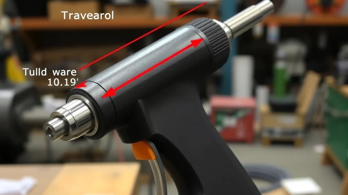
Welding technique conversations stay vague until the angles get named, so let’s name them properly. Every gun position in welding is defined by two angles measured against different reference planes.
The travel angle (also called the push-pull angle or drag angle) is the gun’s tilt along the direction you’re moving — measured from a line perpendicular to the work surface. Point the gun in the direction of travel (leading with the nozzle) and you’re pushing: the arc leads, the puddle trails behind it. Tilt the gun backward (nozzle trailing, wire dragging behind the arc) and you’re pulling or dragging: the arc leads into un-welded metal while the puddle follows in its wake. Perpendicular (0° travel angle) is the neutral reference point — neither push nor pull, rarely used in practice because most processes prefer some tilt one way or the other.
The work angle is the gun’s orientation relative to the joint geometry itself — measured across the joint. In a T-joint fillet, work angle describes where the gun points between the two plates (45° bisecting the corner is neutral). In a butt joint it’s the gun’s lean relative to the plate surface (near-perpendicular). Work angle decides how heat splits between the two members being joined; travel angle decides how the arc and puddle interact with the direction of travel. They’re independent axes — you can drag with a correct work angle or drag with a wrong one, and each combination produces its own bead.
With vocabulary fixed, the push-pull question sharpens into something measurable: at what travel angle should the gun trail or lead for a given process? For self-shielded flux core, the answer has been remarkably stable across decades of industrial practice: drag at approximately 10–15° from perpendicular — a modest trailing tilt, enough to pull the puddle behind the arc, shallow enough to keep the arc aimed into the joint root rather than skimming across the surface. Some experienced welders run slightly steeper drags (up to ~20°) on heavier sections or out-of-position work; a few run near-perpendicular on very thin material where puddle control dominates. The 10–15° window is where the physics, the bead appearance, and the defect rate all converge — and it’s the number every reputable training curriculum teaches first.
Here’s what beginners reliably get wrong, and why: the angle feels wrong. Pushing feels aggressive and purposeful — you’re driving into the work, leading with the arc, the way you’d point a garden hose where you want the water to go. Dragging feels passive, like you’re being towed. New welders naturally push because it matches their intuition about aiming energy at the target. Gene’s “driving into the wind” line lands precisely because pushing is driving — into a headwind of shielding atmosphere flowing the wrong direction. The intuition must be overwritten by understanding, and understanding is what the next section provides.
Why Dragging Is Mandatory: The Shielding Atmosphere Physics

Everything about the drag rule traces back to one fact: with self-shielded flux core, the shielding gas is manufactured at the arc, in real time, by the wire itself. There’s no cylinder, no valve, no hose delivering a steady external flow. The tubular wire’s core contains gas-forming compounds that decompose under arc heat, releasing a small, localized cloud of protective atmosphere — carbon dioxide and other compounds — right at the point of metal transfer. That cloud is your only line of defense between the molten puddle and atmospheric oxygen and nitrogen, which would otherwise oxidize, embrittle, and gasify the weld into scrap.
The cloud’s behavior under your gun angle follows plain fluid dynamics. When you drag (gun tilted backward, arc leading into fresh metal), the newly generated atmosphere flows off the arc zone and settles trailing over the molten puddle directly behind the arc — precisely where the liquid metal sits and where protection matters most. The puddle is born under the atmosphere and stays under it through the critical cooling seconds as it solidifies. The trailing gas blanket also flows over the hot deposited bead and the advancing slag layer, extending protection through the sensitive early-solidification window.
When you push (gun tilted forward, nozzle leading), two failures stack. First, the gun’s motion and orientation direct the generated atmosphere ahead of the arc — into territory that isn’t molten yet — while the puddle sits in the arc’s wake where the atmosphere has already been swept past. The liquid metal ends up covered late or thinly, exactly when it’s hottest and most reactive. Second, the push angle drives the arc plasma and its associated gas flow forward, actively shearing the protective blanket off the top of the puddle; the shielding that was generated gets pushed away rather than laid over. The result is a puddle that spends part of its liquid life partially exposed.
Now layer in what partial exposure actually does to molten steel. Atmospheric oxygen dissolves readily into liquid metal, creating iron oxide inclusions that weaken the deposit and roughen its surface. Atmospheric nitrogen — worse — dissolves into molten steel and, upon cooling, forms iron nitrides that embrittle the weld (nitride embrittlement is a documented reason why nitrogen exclusion matters in welding metallurgy; the technical literature from bodies like TWI and the standards framework of the American Welding Society treat atmospheric exclusion as a first-principle requirement of every arc process). And hydrogen — present in humidity, oil, coatings, and wire moisture — enters an unprotected puddle freely, becoming trapped as the metal freezes and blowing porosity as it tries to escape. That’s the mechanism behind the pinholes: a shielding deficit during liquid life, frozen in time at solidification.
There’s a second shielding function people forget: the atmosphere also protects the slag and the deposit during cooling. The slag blanket needs its own gas cover while it solidifies and while the bead beneath transitions from liquid to solid. A dragged bead delivers trailing gas over this entire sequence. A pushed bead leaves the trailing edge of each fresh pass exposed — which is why pushed flux core welds frequently show discolored, crusted, or powdered slag and oxide-tinted bead surfaces even when the arc itself looked stable.
The quantitative side: self-shielded flux core’s core-generated atmosphere is modest — it’s a small volume produced continuously, not a pressurized cylinder stream. It has enough volume to protect a puddle moving through it correctly and marginally inadequate volume to protect a puddle that the gun’s motion and angle keep evacuating. This asymmetry — barely sufficient when aligned, clearly insufficient when misaligned — is why pushing self-shielded wire fails so reliably. It’s not a subtle degradation; it’s a system operating below its already-tight margin.
One more physical effect completes the picture: arc force direction. The arc’s plasma jet imparts directional force on the puddle — pushing force drives into the joint ahead of the puddle (useful for breaking through surface oxides and forcing penetration into a root), dragging force directs energy slightly into the leading edge of the moving puddle with the deposit settling behind. Dragging combines with the geometry to build a modest penetration profile into the joint root while the puddle’s mass remains controlled and covered. The penetration discussion deserves its own section because it’s where the most persistent counterargument lives.
But Doesn’t Push Give Deeper Penetration? (The Counterargument, Honestly Examined)
You will hear, confidently and repeatedly, that pushing yields deeper penetration than dragging. The claim isn’t fabricated — it’s contextual truth exported out of context, and understanding its origin inoculates you against misapplying it.
In gas-shielded MIG welding (GMAW with solid wire and external gas), research and shop practice both support that push and drag produce meaningfully different penetration profiles: pushing directs arc force and heat ahead of the puddle into un-welded base metal, generally producing deeper penetration for a given setting, while dragging (and gun angle subtleties like “backhand” versus “forehand” technique in older terminology) produces a somewhat shallower, wider profile with better puddle control. Welding research summarized by TWI and process guides from manufacturers like Miller and Lincoln Electric document this directional sensitivity — it’s real physics: the arc jet ahead of a pushed puddle does excavate forward.
Now run that physics through the self-shielded flux core constraint. Yes — pushing might direct more excavation force ahead of the puddle. But the puddle it produces is simultaneously unshielded, oxidized, and contaminated — the penetration groove exists beneath a weld metal that has spent its liquid life partially exposed to atmosphere. Penetration measured under a metallurgically compromised deposit isn’t a virtue; a deep groove with porosity, oxide inclusions, and nitride-affected weld metal at the fusion boundary is a crack waiting for a load. Metallurgical quality and penetration depth aren’t interchangeable scores — codes require both, and process rules exist to deliver both simultaneously. The pushed-flux-core configuration sacrifices the first to chase the second; the drag configuration delivers both.
There’s also the practical bead-geometry reality: pushing on gasless wire tends to produce a narrower, taller, less-surface-controlled bead with inconsistent toe wetting — the visible geometry of a shield-deficit, heat-imbalanced weld. Dragging produces the wider, flatter, evenly-rippled profile associated with properly fused fillet work. Inspectors recognize both instantly, and they know which history each one tells.
The honest summary: for self-shielded flux core, the penetration argument for pushing doesn’t survive contact with the shielding constraint. The arc-tilt penetration physics is real; it’s simply purchased with a currency — atmospheric protection — that flux core can’t afford to spend. When external shielding gas is present (gas MIG, dual-shield flux core), the currency is available, and push technique becomes a legitimate tool with different trade-offs. That’s the exception’s territory, covered in its own section below.
What Goes Wrong When You Push Gasless Wire: The Symptom Map
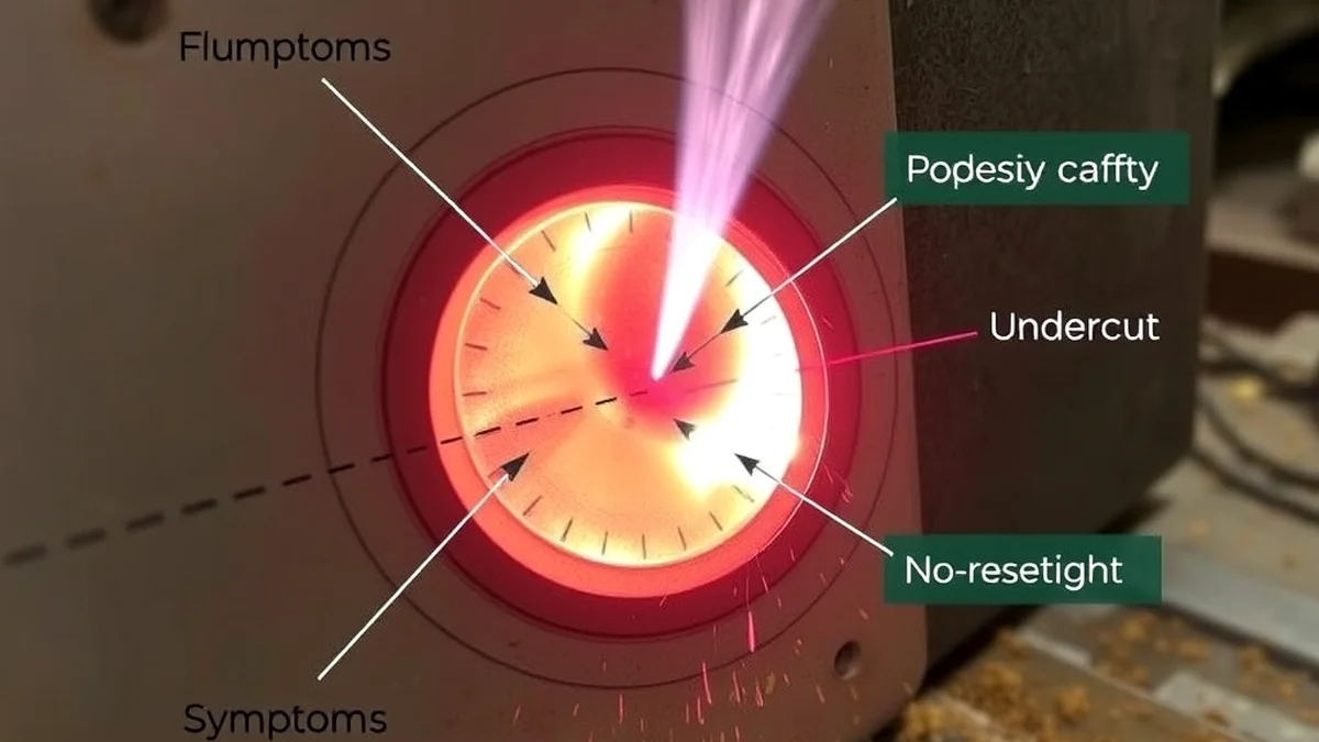
Theory is only useful if it predicts what you’ll actually see in the booth. It does — pushing self-shielded flux core produces a recognizable symptom cluster, and each symptom traces to a specific mechanism. Here’s the field guide to what a pushed bead looks like and why.
Porosity, especially near the top edge and in clusters. The signature defect. The shield-deficient puddle dissolves oxygen and nitrogen during liquid life; hydrogen from ambient humidity or surface contamination enters freely; all of it tries to escape as the metal freezes — and what doesn’t escape in time becomes a pinhole. Porosity from pushing often concentrates along the crown and upper toes of the bead (the surfaces most exposed by the evacuated blanket) rather than distributing evenly (which would suggest bulk contamination instead). If you see that spatial pattern — clean base metal, correct settings, pinholes biased toward the bead’s upper surfaces — gun direction belongs at the top of your suspect list. Full cause analysis: our porosity in welding guide.
Undercut along the leading (upper) toe. The forward-leaning arc deposits its excavation energy at the leading edge of the moving puddle while the trailing deposit has less time and less controlled heat to fill behind — cutting a groove at the toe that the filler doesn’t replenish. Dragging inverts this: the arc leads into virgin metal, the puddle fills the wake, and the toes get fed. Undercut is a fatigue-crack initiator in loaded joints — inspectors reject it for exactly that reason — and a pushed flux core bead’s undercut pattern (leading-edge biased) is diagnostic.
Surface oxides, discolored or crusted slag, and rough bead surfaces. Direct atmospheric exposure of the hot deposit: iron oxides form on the liquid surface, contaminating the bead’s appearance and surface metallurgy; the slag layer forms under partial exposure and comes off discolored, powdery, or inconsistently — sometimes fused into the surface rather than lifting cleanly. A bead that looks “dirty” despite clean base metal and fresh wire is telling you its shielding failed, and if technique is the only variable that changed, direction is the failure.
Weak, inconsistent, and erratic penetration. Paradoxically, despite the theoretical forward excavation, pushed gasless welds often show worse average fusion — the arc wanders more (the atmosphere’s turbulence interacts differently with a forward-facing gun), puddle control degrades (you’re watching and filling a puddle that’s being shielded badly and placed inconsistently), and the toe wetting problems compound. Coupons tell the truth: backside heat tint on butt joints comes uneven, root fusion varies along the length, and cross-sections (when available) show erratic penetration versus the stable profile of dragged welds.
Spatter and arc instability that defy settings fixes. The shield-deficit arc runs visibly rougher — more flicker, more audible pop, more BBs — in a way that misleads welders into dial-chasing. They add voltage (making the puddle bigger and harder to shield), slow travel (increasing exposure time), even swap wire — and the spatter persists, because the variable actually broken is geometric, not electrical. This symptom-cluster-plus-dial-chasing pattern is one of the most common stories in welding forums; the spatter reduction guide names gun angle explicitly in its decision tree for exactly this reason.
Slag that behaves like a stranger. Thick in spots, fused in others, lifting unevenly or not at all — the slag blanket formed under inconsistent gas flow and inconsistent cooling, so it detaches inconsistently. Compare with a dragged bead’s thin, glassy, ribbon-lifting slag and the difference reads instantly. And remember what slag quality signals: underneath it sits the bead — its surface condition reporting the same shielding story the slag tells.
Put the cluster together — biased pinholes, leading-toe undercut, dirty surface, erratic penetration, spatter that won’t tune out, and fussy slag — and you have a pushed-flux-core weld’s fingerprint. Recognize the fingerprint and the fix takes seconds: flip the angle, re-run the joint, watch the defects vanish. The diagnostic table later in this guide maps each symptom to its angle-related cause in tabular form for quick reference at the machine.
The Exception Gallery: When Pushing Becomes Correct
“Always drag” is the right slogan for self-shielded flux core and the wrong universal law — because process design changes the shielding equation, and when shielding changes, geometry rules can legitimately change with it. Three domains where the push question opens up:
Gas-shielded MIG (GMAW) with solid wire. External shielding gas (argon/CO₂ mixtures flowing at 20–35 CFH through the nozzle) replaces flux-generated atmosphere — the protective blanket now comes from a cylinder with volume to spare and no dependence on your gun’s wake. Push (forehand) technique in gas MIG: deeper penetration into un-welded metal ahead of the puddle, faster travel potential, good visibility of the joint ahead — ideal for butt joints on thicker material where penetration matters. Drag (backhand): better puddle control, wider bead, reduced spatter in some situations, preferred for out-of-position and thin-work control. Both are legitimate; experienced MIG welders switch between them by joint and position. Our flux core vs MIG deep dive maps the broader process distinctions.
Dual-shield (gas-shielded) flux core (FCAW-G). Flux core wire plus external shielding gas — the hybrid configuration that industrial fabrication uses for high-deposition structural work. With external gas supplementing (or largely providing) shielding, push technique appears in qualified procedures where its penetration and deposition advantages are wanted. This is decidedly not the gasless home-shop configuration — it requires gas equipment, different polarity conventions (typically DCEN on many setups, the reverse of gasless), and procedure documentation. The category deserves recognition because it’s the direct demonstration that the drag rule belongs to gasless operation specifically, not to the tubular wire family as a whole: our what is dual-shield welding explains the configuration fully.
Special situations on gasless wire where near-perpendicular or very slight angles are used. Root passes in open-root joints sometimes run near-perpendicular or with minimal angle adjustments for puddle placement; some vertical-up sequences modify angle through the weave cycle (tilting slightly side to side to direct the puddle into each toe); overhead work often pulls with a slightly reduced angle to minimize puddle size. These are modulations of the drag — never full reversal into push — and they come from qualified technique traditions rather than casual preference. The unifying principle: shielding alignment is maintained (arc’s wake still covers the puddle) while angle varies within the trailing regime.
The clarity statement worth memorizing: self-shielded (gasless) flux core = drag, period. Gas-shielded processes = push or drag as joint, position, and procedure dictate. If someone tells you they push gasless wire and it “works fine,” ask to see their coupon’s surface condition, their porosity on a cut section, and their service history under load — the three questions that separate “ran without visible disaster” from “produced acceptable welds.”
Travel Angle in Depth: The 10–15° Window and What Lives Outside It
Within the drag regime, angle still has a range — and each deviation from center trades one property for another. Understanding the window lets you adjust deliberately instead of accidentally.
Shallow drag (5–10° from perpendicular): The arc points nearly straight down with slight trail. Puddle sits directly beneath the arc — maximum control, minimal directional force, good for thin material and flat-position fine work. Trade-offs: slightly less puddle-driving force into joint roots, and the trailing atmosphere’s directional bias is milder (fine when conditions are calm, less robust when drafts or repositioning disturb the wake). Some welders live here for sheet metal work where puddle size dominates all other concerns.
Standard drag (10–15°): The working window for general flat and horizontal fillet and butt work. Enough trail to keep the atmosphere blanket flowing over the puddle with directional certainty, enough forward aim to drive the arc into the joint root for fusion, and a natural hand position that’s stable through long passes. This is where technique becomes quiet — the angle supports everything else you’re doing rather than demanding attention.
Steeper drag (15–20°+): More trail means the arc’s leading edge strikes more surface ahead of the puddle while the deposit trails further behind — useful on heavier sections where you want the puddle pulled and set with more deliberation, and common in vertical-up weaving where the gun’s geometry naturally steepens as you climb. Trade-offs: the forward arc component into the joint root diminishes (potential root fusion loss on open roots), and the gun’s nozzle-to-work geometry gets awkward in tight joints. Beyond ~25°, the contact tip-to-work distance effectively lengthens and the arc begins skimming rather than driving — arc stability and penetration both suffer.
The angle-stickout interaction deserves emphasis because it’s rarely taught alongside the angle rule: as you tilt the gun, the perpendicular distance from contact tip to work shortens (or lengthens, depending on pivot point) even if your hand position feels unchanged. A steep angle unintentionally shortens stickout — dropping your effective amperage (per the resistance-heating physics covered in our settings guide) — while a shallow angle lengthens it. Angle changes are therefore never purely geometric; they’re electrical too. The disciplined welder evaluates stickout after setting angle, not before, and checks that the combination hasn’t silently moved arc amperage outside its window. The full interaction analysis lives in our techniques masterclass.
Travel speed couples in as always: drag angle at correct speed produces the standard profile; the same angle at excessive speed leaves narrow, under-wetted beads (the puddle never catches up to the arc); the same angle at excessive slowness floods the joint with heat and metal. Angle, speed, and stickout form a tripod — adjust any leg and the other two’s correct values shift slightly. That’s not instability; that’s a coupled system behaving as physics requires.
Work Angle: Where the Gun Points Across the Joint
Travel direction gets the headlines, but work angle decides whether heat lands where the joint needs it — and it fails in quieter, sneakier ways. The reference geometry by joint type, all assuming drag travel:
| Joint Type |
Work Angle Starting Point |
What Wrong Looks Like |
Signature Symptom |
| T-joint fillet (2F flat) |
45° bisecting the corner |
Gun biased toward one plate |
One toe wetted, the other cold and rolled; lopsided throat |
| Butt joint (1F/1G) |
Near perpendicular (~90°) |
Leaned left or right of seam |
Fusion favors one plate; root offset; uneven cap |
| Lap joint (2F) |
Slightly toward the vertical member (~15° bias) |
Perpendicular or biased to the flat sheet |
Upper plate edge melts back; lower plate unfused |
| Outside corner |
Pointed at the intersection of edges |
Aimed at one leg only |
One edge blown away, other untouched |
| Fillet, out of position |
Bias slightly uphill of neutral |
Neutral flat angle reused vertical |
Gravity pulls puddle down; top toe starves |
The pattern across the table: an incorrect work angle doesn’t usually destroy the weld outright — it tilts it, giving you one properly fused toe and one deficient, one thick side and one thin, and asymmetry that inspection catches even when visual confidence doesn’t. The reason work-angle errors hide is that the bead often still looks continuous from the top; you have to examine both toes (or the backside, or a cut) to see that the joint’s throat — the imaginary line through the weld’s thinnest section, which determines fillet strength — is thinner than the bead’s surface suggests. Our weld strength guide explains why throat geometry, not bead width, governs load capacity — which is exactly why work-angle discipline is a structural issue wearing a cosmetic costume.
The deeper principle unifying travel and work angle: the gun position defines where arc energy divides between base metal and filler, and that division must serve the joint’s design. A fillet needs equal fusion into both members (hence bisect); a lap needs the arc’s attention on the thicker-feeling seam where the two plates overlap; a butt needs straight-down symmetry so both edges melt at matched rates. Drag direction protects shielding; work angle serves joint geometry. Two axes, two purposes, both non-negotiable — and both visible in the finished bead for anyone trained to look.
A practical note on hand mechanics: work angle drifts most when the welder’s body is poorly positioned. If you start a fillet with the gun bisecting the joint but your arm is extended at an uncomfortable reach, the angle will flatten progressively as the pass advances — the bead’s start looks right, the middle leans, the end is wrong. The fix is upstream: reposition (kneel, sit, rotate the workpiece, use a fixture) so the natural arc of your arm sweep holds the work angle constant through the entire pass. Locked wrist, movement from shoulder or elbow, body aligned behind the gun — the ergonomics of consistency, covered with drills in our techniques masterclass.
Position Interactions: Drag Direction Under Gravity
A natural question from welders moving into out-of-position work: does changing position change the push-pull answer? The answer is no — position modulates angle, speed, and settings, but the drag requirement holds in every orientation, because shielding physics doesn’t reorient itself when you climb a wall.
Vertical-up is the clearest case. The gun drags upward, trailing the arc as the puddle builds on the shelf below — gun tilted slightly back from the climb direction, weave pausing at each toe, each segment resting on solidified metal. The trailing atmosphere blankets each fresh segment as it’s deposited and stays over the cooling stack. Tilt the gun downhill instead (which some welders do by accident when they lean into the climb) and you’ve effectively introduced a leading nozzle — shielding flows uphill over nothing while the fresh puddle below sits exposed. Vertical technique details and settings: our vertical-up settings guide.
Horizontal fillets drag along the seam with the work angle biased slightly toward the upper plate (gravity’s tax on the puddle pulls it across the joint face; the bias counters it). The travel direction stays a trailing drag — the atmosphere follows the puddle around the joint’s horizontal plane exactly as it does in flat work. Settings trim downward from flat baseline per our horizontal settings guide, but direction never flips.
Overhead is where drag technique’s shielding benefit matters most — the puddle hangs exposed beneath the work, defying gravity with surface tension and arc force, and a trailing atmosphere flowing over the underside of the joint provides the protection that a leading gun would blow away. Overhead also demands the lowest heat of any position (to keep puddle mass manageable) and the most committed travel — hesitation lets the puddle sag, and sagging overhead can’t be fixed with angle adjustments mid-bead. The full overhead profile — settings, body position, helmet angle, PPE for falling spatter — appears in our techniques masterclass, and the safety dimension (overhead spatter falls into collars, boots, and helmet gaps) anchors our welding safety tips.
There’s one legitimate directional exception across positions, and it belongs to thin-sheet vertical-down work: on light material, vertical-down dragging with fast travel and reduced settings produces controlled, shallow-penetration beads without puddle sag — a technique used in bodywork and light fabrication. Note carefully that this is still drag (gun trailing); the “downhill” describes travel path, not gun orientation relative to the arc’s wake. The vocabulary trap trips people up constantly: downhill travel with a trailing gun is a drag; uphill travel with a trailing gun is a drag; the gun’s relationship to the arc’s wake is what defines the technique — not the compass direction of the seam.
The Angle Diagnosis Table: Matching Defects to Geometry
When a bead misbehaves and settings check out, angle is the next suspect — and the specific defect pattern tells you which angle variable broke. This table converts symptom to geometry:
| Observed Symptom |
Most Likely Angle Error |
Secondary Suspects |
Corrective Action |
| Pinholes biased to bead crown/upper toe |
Pushing (leading nozzle) with gasless wire |
Wind exposure; damp wire; contaminated joint |
Flip to 10–15° drag; verify shielding path; clean and re-test |
| Undercut along one toe, consistently |
Work angle biased toward that side |
Voltage high; travel too slow at that edge |
Re-center work angle; trim heat; check both toes wet evenly |
| Leading-toe undercut, rough surface |
Pushing, or drag too steep (>25°) |
Voltage high; stickout short |
Return to 10–15° drag; measure stickout after re-angling |
| One plate fused, other rolled/cold |
Work angle favoring the fused plate |
Insufficient amps for joint mass; travel fast |
Bisect the joint; confirm both toes wet; check penetration |
| Bead wanders off the joint line |
Body position forcing mid-pass angle drift |
Feed pulsing; worn tip; loose ground |
Reposition before starting; drill stringers; inspect feed system |
| Slag discolored, powdery, lifts badly |
Insufficient trailing coverage (push or excessive angle) |
Damp wire; travel too slow; contaminated surface |
Verify drag geometry; check wire storage; clean joint |
| Spatter that won’t tune out |
Push-induced shield deficit (looks like parameter issue) |
Polarity wrong; stickout too long; worn contact tip |
Verify direction, then polarity, then stickout — in that order |
| Narrow tall bead despite adequate settings |
Drag too steep + travel too fast combo |
Wire speed low; stickout too short (amps low) |
Shallow angle to 10–15°; steady speed; recheck stickout |
Two diagnostic disciplines make this table work in real time. First, change one variable — flip direction (or re-angle), re-run, observe; if the symptom clears, you’ve found it; if it persists, move down the suspect list. Angle-first diagnosis works because angle is the variable most often wrong and least often checked — settings get verified constantly, polarity occasionally, gun geometry almost never. Second, test on scrap of matching thickness — angle-related defects interact with heat input, and a coupon at project thickness reproduces the real behavior that a heavy scrap plate would mask. The full diagnostic framework beyond angle lives in our troubleshooting playbook.
Installing the Skill: Four Drills for Angle Discipline
Knowing the angle and holding the angle are separate competencies — the second one lives in muscle memory, and muscle memory only develops through targeted repetition. Four drills that build it efficiently, in progression order:
Drill one: the paper-angle check. Before striking an arc, set your gun at the intended drag angle against a printed protractor (or a simple 90° and 15° card taped to the bench) — sight along the gun and match. Run a bead. Re-check visually. Repeat until your hand lands at 10–15° without the card. This drill calibrates proprioception: your sense of “15° tilt” is probably wrong on day one and accurate by day three.
Drill two: the mirror pass. Prop a mirror beside a plate joint so you can watch your own gun from the side while welding (through the helmet — position the mirror so the reflection is visible in your peripheral view without looking away from the puddle). Ten seconds of side-view feedback reveals angle drift your eyes, locked on the puddle from behind, cannot see. Filmed video of your hands (phone on a tripod) serves the same purpose for review after the session.
Drill three: constant-angle stringers. Three-inch stringers on plate where the only success criterion is uniform bead width start to finish (width variation is angle or speed drift — isolate angle by holding speed deliberately steady). Mark the intended path, run the bead, measure width at start, middle, end with a caliper or visual comparison. Repeat until width delta shrinks below ~10%. Log the session — our home practice guide structures this progression.
Drill four: joint-angle circuit. Set up four joint types in sequence — T-fillet, butt, lap, outside corner — and run one careful pass on each, re-setting work angle between joints while holding travel drag constant. The drill cements that work angle is joint-dependent while drag direction is process-dependent — the conceptual distinction that keeps the two axes from blurring. Evaluate each bead’s two-toe symmetry before moving to the next joint.
Twenty minutes a session across a few weeks converts the geometry from conscious effort to default. The investment pays beyond this process: the same angle discipline governs gas MIG technique (where push becomes an option but work-angle rules carry over identically) and stick welding (where electrode angle serves the same dual purpose) — angle fluency is transferable craft capital, detailed in our beginner welding tips.
Sorting the Forum Arguments: Myths About Push and Pull
The push-pull debate generates more circular online argument than almost any other technique topic, because participants routinely argue from different processes, different positions, and different definitions without announcing any of the three. Let’s defuse the four arguments that recur most:
“I push gasless wire and my welds pass inspection.” Sometimes true — in light-duty, non-code applications where visual acceptance is the only bar, a pushed bead on clean material with fresh wire may look passable. The claim collapses under three questions: what does a cut section show (porosity and inclusion rates hide under acceptable surfaces), what’s the service history under load (fatigue and brittle behavior live below the visual threshold), and would a qualified procedure permit it (codes specify direction for FCAW-S for the shielding reasons we’ve traced — no inspector signs off a reversed direction casually). “It passed my eye” and “it meets the standard” are different claims, and the gap between them is where structural failures eventually live. Standards context: AWS specifications.
“Pushing is standard practice — every MIG video pushes.” Correct observation, wrong transplant. Those videos show gas MIG, where cylinder-fed shielding makes push technique legitimate — the exception gallery above covers why. The rule follows the shielding source, not the machine’s shape: same-looking gun, same-looking wire feed, completely different atmosphere physics. Process literacy — knowing which process a demonstration actually shows — is the filter this argument fails.
“Angle doesn’t matter, settings are everything.” Settings define what the arc can do; angle defines what the atmosphere and puddle actually do with the opportunity. Perfect voltage and feed with a pushed gun produces the defect fingerprint anyway — which is why angle belongs in every diagnostic sequence and why our costly mistakes catalogue ranks direction errors near the top. A machine can’t compensate for a geometry that evacuates its own shielding.
“Drag or push — just pick one and be consistent.” Consistency with the wrong technique produces consistently bad welds — the worst outcome, because it removes even the accidental successes. Direction isn’t a style preference like weave pattern; it’s a process requirement with a physical basis. Consistency matters only after correctness: hold 10–15° drag consistently because that’s where shielding, penetration, and puddle control all succeed.
The meta-lesson across all four: arguments about technique are really arguments about unstated premises. Pin down the process (gasless vs gas-shielded), the position, the definition, and the acceptance criteria — and most push-pull disputes evaporate into agreement. That’s not debate aversion; that’s engineering communication.
Three Real Projects, Three Angle Lessons
Scenario one — driveway trailer rail repair, flat and horizontal fillets. A cracked rail section, cleaned and beveled, welded with fresh E71T-11 on a 180-amp 220V machine. Travel angle: standard 12° drag throughout, re-set at each segment restart (restarts are where angle discipline typically collapses — the gun comes in hastily and the first inch runs at whatever angle the approach produced). Work angle: bisect on the main fillet, slight upward bias on the horizontal segment where gravity pulled the puddle across the joint face. Result: uniform toes both sides, slag lifting in ribbons, and a repair that carries the rail’s load through the throat the bisected angle guaranteed. The project’s lesson: re-verify angle at every restart — mid-pass discipline is worthless if each new pass begins wrong.
Scenario two — vertical-up column stiffener, out of position. Settings trimmed from flat baseline per our vertical-up guide; gun trailing the climb with a triangle weave, pauses at each toe, segments of five inches tied carefully into each other. The angle lesson here: gun geometry shifts naturally as your arm rises through a climb — starting correctly and ending flat (or worse, leading) is the classic vertical failure. The countermeasure: segment the climb into short passes with repositioning between them, re-setting the trailing angle each time instead of stretching a single pass to arm’s length. Fatigue-driven angle drift is as real vertically as horizontally; the wall just hides it better.
Scenario three — overhead pipe support bracket, thin-wall tube meeting plate. Overhead fillets at reduced heat, drag angle held tight, stringers only (weaving overhead turns control into luck), and the constant awareness that every deviation of the trailing angle lets the puddle’s shield drain sideways while gravity works the metal below. Speed: committed — the one position where hesitation hurts more than any wrong-but-steady setting. The angle lesson: overhead rewards the standard drag more than any other position, because there’s no fallback — a leading gun overhead exposes the puddle that’s already fighting gravity. Safety note before the session: full collar coverage and gauntlet overlap — overhead spatter falls straight down, as our safety guide insists. (And for the material decision behind choosing flux core for this job — outdoor access, no gas bottle — our gasless flux core guide walks the trade-offs.)
Across all three: direction was never the variable under debate — it was the fixed premise from which every other adjustment proceeded. That’s how professionals treat it: correct shielding geometry first, then tune settings, speed, and weave within the space it opens.
The Angle-Settings-Polarity Triad: Diagnosing as a System
Angle never operates alone — it sits inside a triad with polarity and settings, and the three variables share symptoms so freely that misattributing one for another is the single most common diagnostic error in flux core work. Build the triad into your troubleshooting reflex and half the mysterious welds in your shop resolve before you touch a dial.
Polarity is the gatekeeper. Before angle analysis even begins, confirm DCEP — because wrong polarity on gasless wire produces a symptom cluster (wild unstable arc, wire melting back at the tip, heavy spatter, negligible penetration) so similar to push-induced defects that welders routinely re-angle good technique while the real fault sits in the cable connections. The check takes ten seconds: follow the electrode lead to the positive terminal, or consult the machine’s front-panel labeling (which varies by manufacturer and era — the polarity guide decodes the labeling traps and the verification bead test). Polarity first, then angle, then settings — that order is not negotiable, because each variable’s defect signature overlays the next.
Settings interact with angle through stickout and heat input. We covered the angle-stickout coupling earlier — tilting the gun changes tip-to-work distance and therefore effective amperage — but the settings dimension runs deeper. A welder who drags correctly but runs voltage too low sees cold, ropey beads with poor toe wetting that look like angle trouble; a welder running wire speed too high sees a stubbing, driving arc that mimics the instability of a pushed bead. The disambiguation path: re-set angle to the 10–15° window, verify stickout with a ruler, then walk the settings one variable at a time using the chart baselines from our wire speed and voltage chart and amperage chart. The full parameter framework — how voltage, feed, polarity, and stickout co-determine arc behavior — is systematized in our parameters guide.
Practice the integrated diagnosis on scrap. Set a plate at project thickness, run a bead with your normal technique, and evaluate in triad order: direction correct? (flip and re-run if the symptom cluster persists, direction is eliminated). Polarity verified? (terminal check or clamp-meter reading). Stickout measured after angle set? Only when all three gates pass do settings adjustments mean anything — dial-chasing before that point fixes symptoms while causes compound. The discipline converts vague \”something’s off\” sessions into structured hunts that terminate in answers, and it’s the same framework our costly mistakes catalogue and troubleshooting playbook use as their spine.
Two system-level checks round out the triad because they amplify every variable within it. Input power quality: extension cord voltage sag starves the machine of the energy its dial promises — settings that worked yesterday through a short lead misbehave today through fifty feet of undersized cord, and the arc symptoms (weak, cold, erratic) impersonate technique failures. Size the cord for the amperage draw per our breaker and wire sizing guide, and verify duty cycle headroom on sustained passes per our duty cycle article — a machine in thermal rollback delivers less than its settings request, and no angle correction compensates for that. Feed system condition: worn drive rolls, a clogged liner, or a stretched gun neck makes the wire arrive at the arc with pulsing, hesitation, or contamination that destabilizes puddle geometry regardless of perfect gun angle — feed inspection per our drive roll guide belongs in any diagnosis that survives the triad checks but still misbehaves.
Expert framing from industrial training practice: technique variables are judged inside a stable system, not against it. The American Welding Society’s procedure philosophy — formalized in the AWS standards framework — treats operator technique, equipment condition, and consumable state as one qualified system; change any element outside its window and the technique’s documented performance no longer applies. Your shop version of that principle: verify the system (polarity, power, feed), then judge the technique (angle, speed, weave), and the triage never inverts.
Gun Angle in Confined Spaces and Real Fabrication
Everything above assumes comfortable access — plate on a bench, arm free, sightline clear. Real fabrication spends much of its life violating those conditions, and confined access distorts gun geometry in ways worth anticipating deliberately rather than improvising under the arc.
Tight inside corners and boxed assemblies force the gun into angles the welder would never choose: the nozzle can’t reach the intended 12° trailing tilt because the frame member blocks the gun body, so the welder compromises — often unknowingly drifting toward neutral or leading geometry to make the nozzle fit. The countermeasures are practical. First, sequence the assembly so the difficult joint welds in the most accessible orientation remaining (welding-order planning is a fabrication skill, not an afterthought). Second, shorten stickout deliberately rather than tilting to reach — a reduced stickout in a confined joint holds the trailing geometry even when the gun body can’t swing wide, with the settings adjustment for shortened stickout applied per our settings guide. Third, accept smaller beads in multiple passes over one stretched pass attempting full throat in a single access — the multi-pass route keeps each pass’s geometry correct inside the space available.
Out-of-position access compounds the problem. Under a vehicle, inside a tank bay, or overhead between joists, the welder’s body position controls the gun position — and here the ergonomics principle from the practice drills pays directly: if you can’t hold the trailing angle through the pass from your current stance, the stance is wrong, not the angle. Move the workpiece, use mirrors for sightlines, reposition the body, or — where none of that is possible — shorten passes to segments your geometry can honestly hold, re-setting angle at each restart. The helmet matters more than welders admit in awkward positions: a heavy or badly balanced hood makes the fine head angles that sightline demands a fatigue source, and fatigue degrades angle discipline fastest of all — fit guidance lives in our how welding helmets work explainer, and the comfort-related equipment choices in our beginner machine reviews account for gun balance and lead flexibility that make angle control easier at awkward reaches.
Outdoor and drafty sites add the wind variable to geometry. A trailing angle that shields perfectly in a still shop can have its atmosphere blown across the joint when a breeze enters from behind the welder — direction still correct, blanket displaced anyway. The site fix: shelter first (windbreaks, positioning the vehicle or structure as a shield, welding on the leeward side of the work) before any angle or settings compensation, because brute-force adjustments can’t restore an atmosphere that keeps relocating. Fume management also shifts with wind: redirected plume means respiratory protection upgraded from optional to required, per the exposure framework in our welding fumes guide and the equipment picks in our respirator guide — with OSHA’s welding and cutting standard setting the enforceable exposure limits and NIOSH’s welding research documenting why the wind-shifted plume deserves respect. Site-condition context for why gasless flux core earns its outdoor reputation (and its limits) appears in our gasless flux core guide.
Read together, the confined-space section delivers one meta-principle: access problems are angle problems wearing a logistics costume. When a weld comes out wrong in an awkward location, the first question isn’t \”what settings do I change?\” but \”could I physically hold correct geometry through that pass?\” — and if the honest answer is no, the fix is sequence, fixture, or segment, not dial. The welder who internalizes that inversion stops fighting geometry with parameters and starts designing access around the technique the process requires.
Frequently Asked Questions
Do I always drag flux core wire?
For self-shielded (gasless) flux core — yes, with rare modulations within the trailing regime (near-perpendicular on thin open roots, slight side-tilts during vertical weaves). The 10–15° trailing drag is the process default because it aligns the flux-generated shielding atmosphere with the molten puddle. The rule changes only when shielding changes: gas-shielded MIG and dual-shield flux core can push or drag by joint and procedure. If gas isn’t flowing from your nozzle, the gun trails. Period.
Why exactly does pushing cause porosity with flux core?
Because the shielding atmosphere your wire generates at the arc gets directed ahead of the puddle by the forward-leaning gun, while the molten metal sits in the arc’s wake with thin or delayed coverage. The exposed liquid dissolves oxygen and nitrogen from the atmosphere, and hydrogen (from humidity or surface contamination) enters freely — all trying to escape as the metal freezes. Undissolved gas becomes pinholes. The characteristic pattern — porosity biased toward the bead’s crown and upper toes rather than evenly distributed — distinguishes push-related shielding loss from bulk contamination. Mechanism details: our porosity guide.
Is it true pushing gives deeper penetration?
In gas-shielded MIG, yes — research and practice both show pushed arcs excavate further ahead of the puddle. For self-shielded flux core, the claim is true in isolation and useless in context: the deeper groove arrives with a shield-deficient, contaminated deposit — penetration quality beneath compromised weld metal doesn’t produce a sound joint. Codes require fusion and metallurgical quality; dragging delivers both for gasless wire, pushing trades one for the other. When external gas is present (MIG, dual-shield), push technique’s penetration benefit becomes a legitimate tool.
What exact angle should I drag at?
Start at 10–15° from perpendicular — the trailing tilt where atmosphere blanket, root penetration, and hand stability all align for general flat and horizontal work. Shallow the angle (5–10°) on thin material for tighter puddle control; steepen (15–20°) on heavier sections or vertical climbs where deliberate puddle placement helps. Avoid exceeding ~25° (arc skims, stickout shortens, penetration fades) and never cross into leading-nozzle territory. Verify stickout after setting angle — tilting changes the tip-to-work distance and your effective amperage.
Why does only one side of my fillet weld wet properly?
Work angle bias — the gun is pointed at the plate that fuses while the opposite toe rolls cold. Re-center to bisect the joint (45° for a standard T-fillet), confirm both toes wet evenly on a test pass, and check your body position: an unstable reach lets work angle drift as the arm extends, producing one-sided fusion that starts right and leans. Secondary suspects if angle checks out: insufficient amps for the joint’s heat sink, or travel speed too fast for the puddle to wet both sides.
Does vertical-up welding change the drag direction?
No — vertical-up is still a trailing drag, with the gun tilted back from the climb so the atmosphere blankets each freshly deposited segment as it shelves onto the solidified metal below. What changes: settings trim downward (5–15% per our vertical-up settings table), weaves pause at the toes, and segments shorten with repositioning between them (arm extension during a climb causes angle drift — the classic vertical failure). Traveling “downhill” on thin sheet also keeps the gun trailing; travel path and gun orientation are independent variables.
Can I push with gas MIG instead?
Yes — gas-shielded MIG supports both push (forehand) and drag (backhand), chosen by joint, position, and goal: push for deeper penetration and faster travel on butts and heavier material; drag for puddle control, reduced spatter, and out-of-position work. The cylinder-fed atmosphere covers the puddle regardless of gun direction, which is exactly why the flexibility exists. The full process comparison — and when each process (including gasless flux core) suits the job — lives in our flux core vs MIG breakdown and gas vs flux core comparison.
My weld looks wrong — should I check angle or settings first?
Angle, almost always — it’s the most-wrong and least-checked variable. The working order: (1) gun direction correct (trailing for gasless), (2) work angle centered on the joint, (3) polarity verified (DCEP), (4) stickout in spec after angle set, (5) joint clean, (6) then dial settings. That sequence resolves a surprising share of “bad settings” mysteries — welders who dial-chase with a pushed gun spend evenings fixing symptoms while the cause sits in their hand. Full diagnostic flow: our troubleshooting playbook.
Does work angle differ between flux core and MIG?
No — work angle is joint geometry, not process. T-joints bisect at 45°, butts run near-perpendicular, laps bias toward the vertical member in both processes. What differs: travel direction freedom (gas MIG may push or drag; gasless drags) and settings windows. This is why work-angle skill transfers intact across wire processes and largely into stick (electrode angle serves the same heat-splitting purpose). Learn it once, apply it everywhere — our techniques masterclass treats it as a universal axis.
How can I prove to myself that direction matters?
The ten-minute experiment: clean 1/8″ plate, same settings, same wire, same everything — run three 3-inch beads: dragged at 12°, near-perpendicular, pushed at 12°. Photograph each. Compare surface color and texture, bead profile and toe wetting, slag behavior — then run a wire brush across each and look for pinholes at the crown. Then (if you own a grinder) cut and etch or at minimum inspect the backside heat tint for penetration consistency. The coupons teach the physics with zero rhetoric — and they belong in your reference notebook alongside the settings experiments from our practice guide.
The Direction That Protects the Weld
Strip the push-pull debate to its physics and it becomes almost embarrassingly simple: your wire manufactures its own shielding at the arc, that shielding flows where your gun angle sends it, and the molten puddle needs it flowing across — not away from — itself. Dragging at 10–15° places the blanket exactly where liquid metal waits for protection; pushing sends the blanket ahead into solid territory and leaves the puddle to fend against oxygen, nitrogen, and hydrogen with whatever turbulence happens by. The defect fingerprint of getting it wrong — biased pinholes, leading-toe undercut, dirty surfaces, erratic penetration, spatter that defies tuning — is as recognizable as a signature once you’ve seen it twice.
The exceptions are real and they’re boundary conditions, not loopholes: gas-shielded processes carry enough atmosphere from a cylinder to survive direction changes, dual-shield flux core joins them, and within the gasless regime, modulations of the trailing drag (shallower on thin work, steeper on climbs) stay inside the shielding logic rather than breaking it. Know which process’s rulebook you’re holding and the right answer arrives before the question finishes forming.
Gene’s five words — “you’re driving into the wind” — compressed all of it into an image you’ll never forget: direction carries the atmosphere, atmosphere carries the weld. Marcus’s rail passed inspection on the first re-run, by the way — same machine, same settings, same wire, flipped angle. He still drags. And now, understanding exactly why he does, so will you: set the trailing angle, keep it constant through the pass and at every restart, let the settings do their work inside the geometry that shielding requires, and let the bead’s even ripples and ribbon-lifting slag confirm what the physics already promised. Correct direction isn’t a technique tip — it’s the process working exactly as designed.