Roy had a piece of paper taped inside his welding cabinet — a settings card he’d built over two years of trial, a grid of thicknesses across the top and, inside each cell, the voltage and feed numbers that had worked for him on his specific machine. It was meticulous. It was hard-won. And for six months it had made him reliably good: pull the card, dial the numbers, weld. Then one Saturday a job arrived that his card had no answer for — a patch on 16-gauge fender steel welded at an awkward upward angle, with a wind coming across the driveway — and Roy discovered something uncomfortable about his system. The numbers were right and the welds were wrong. Every cell in his grid assumed the same stickout, the same gun angle, the same travel speed, the same clean metal, and the same machine on a full-power outlet. Change any assumption and the card’s numbers stopped meaning what he thought they meant.
What Roy had actually built wasn’t a settings guide — it was a photograph of one. And what he needed, what every welder eventually needs, is the moving picture: an understanding of flux core welding parameters as an interconnected system where no number has an absolute meaning, where voltage means one thing at a half-inch stickout and something else at an inch and a half, where “wire speed” is really amperage wearing a different hat, and where the honest answer to “what settings should I use?” is always “for what material, in what position, at what stickout, on what machine, welded how?” — followed by a number.
That’s the subject of this guide: the complete parameter system for flux core welding. Every variable that touches the arc, what each one physically does, how the pairs and trios interact, how to tune them systematically instead of by superstition, and how to recognize which parameter has drifted when a weld suddenly misbehaves. The goal isn’t a better card for the cabinet door — it’s retiring the card entirely, because a welder who understands the system can derive the right numbers for any situation, including situations no chart has ever seen.

Key Takeaways: The Parameter System in Seven Lines
- Parameters are a system, not a list. Voltage, wire feed (amperage), stickout, polarity, angle, and speed each change what the others mean — tune the interaction, never a number in isolation: settings guide.
- Wire feed speed IS your amperage dial. On the constant-voltage machines most welders own, feed rate determines how much current the arc draws — the “amps” label on cheap machines is really a feed label underneath: amperage chart.
- Voltage sets arc length and bead profile. Too low: cold, narrow, high crown; too high: wide flat bead, spatter, undercut risk. It pairs with feed — both rise together when thickness increases.
- Stickout is a hidden parameter. Tip-to-work distance changes effective amperage through resistance heating — measured after setting angle, every session.
- Polarity is parameter-zero. DCEP for self-shielded wire — every other parameter’s window is defined on the assumption it’s correct: polarity guide.
- Position adjusts the whole set. Vertical-up, horizontal, and overhead trim the flat-window baseline by roughly 5–15% while technique variables tighten: horizontal and vertical-up guides.
- Tune one variable at a time with test beads. Sound, puddle, and bead appearance are the instruments; charts are starting points, not destinations: practice method.
With the map sketched, walk it in order — starting with the family portrait: what each parameter actually is.
The Parameter Family: Every Variable That Touches the Arc
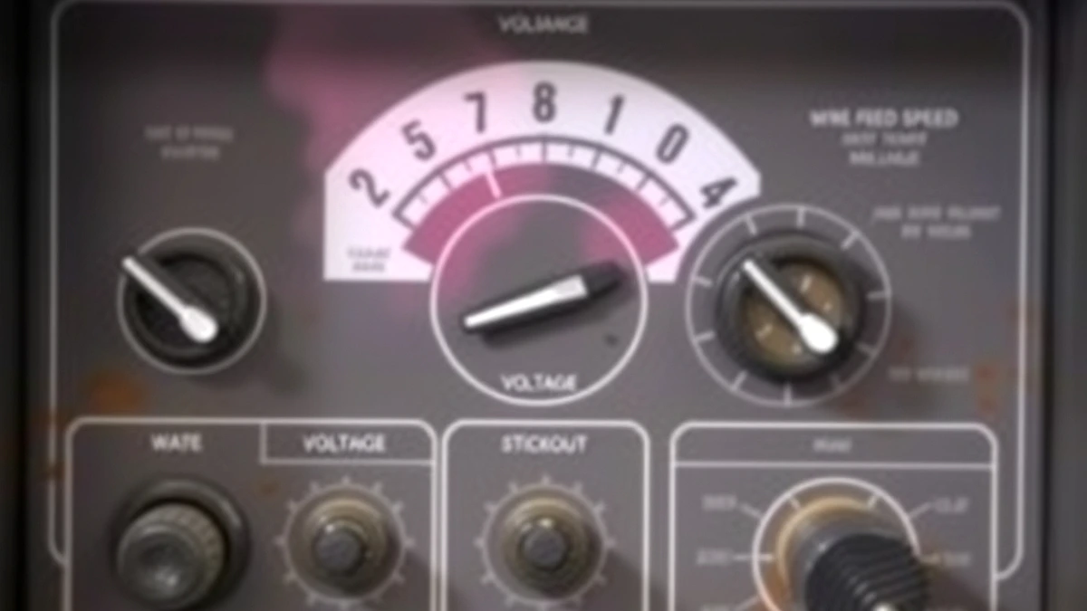
Ask ten welders which parameters matter and you’ll get answers ranging from “voltage and wire speed” to a shrug. The accurate answer has three tiers: electrical parameters (voltage, wire feed speed/amperage, polarity), geometric parameters (stickout, travel angle, work angle, travel speed), and contextual parameters (wire diameter, material thickness and type, joint geometry, position, shielding condition, machine and power-supply characteristics). The tiers interact constantly — geometry changes the electrical reality, context sets the windows for both — and mastery lives in seeing the whole board at once rather than the dial in isolation.
Voltage is the electrical potential the machine presents to the arc — the force pushing current across the gap. It governs arc length (how far the arc stretches between wire tip and puddle), which in turn governs bead width, penetration profile, spatter production, and how forgiving the arc feels as travel speed varies. Too little voltage and the arc keeps shorting itself out — the wire stubs into the puddle, the arc pops and sputters, the bead climbs into a tall narrow crown with poor toe wetting. Too much and the arc stretches long, the puddle flattens and spreads, spatter rises, and the edges of the bead undercut as the arc’s energy washes past the toes instead of feeding them. The correct voltage is the one where the arc runs with a steady, quiet crackle and the puddle wets both toes without spreading beyond the joint.
Wire feed speed (WFS) is how fast the drive rollers push wire toward the arc — and on the constant-voltage machines that dominate the consumer and light-industrial market, it’s simultaneously your amperage control. The physics: faster feed means more wire arriving to carry current, which means the arc draws more amps to melt it; slower feed means less wire, less current. This is why cheap welders label the feed dial “Amps” — the causal chain from knob to current runs through wire speed. The pairing is why voltage and feed are never tuned independently in practice: more feed demands more voltage to keep the arc length stable as current rises, and the two climb together from sheet to plate.
Polarity decides which direction electrons travel — and with them, where heat concentrates and how the flux’s chemistry behaves. Self-shielded flux core runs DCEP (electrode positive); wrong polarity doesn’t shift your window, it destroys it, producing an arc that no voltage or feed setting can rescue: full polarity mechanics.
Stickout (contact tip-to-work distance, CTWD) is the geometric parameter with electrical consequences: the wire between tip and arc acts as a resistor, heating before it arrives — longer stickout preheats the wire and lowers effective arc current, shorter stickout does the reverse. Change it a half-inch and you’ve moved your amperage by a meaningful margin without touching a dial. Travel angle (the drag tilt) and work angle (orientation across the joint) direct where the arc’s energy lands and how the generated shielding flows over the puddle. Travel speed sets the energy-per-inch equation: heat input scales with amps and voltage divided by speed, which is why an identical bead at half speed deposits twice the heat into the plate.
Contextual parameters set the windows before tuning begins: wire diameter determines the feed range that carries correct current (.030 vs .035), material thickness sets total energy demand, joint geometry decides where that energy must split (work angle), position tilts the whole window against gravity, and machine characteristics — rated output, duty cycle, input power quality — determine whether the window on your chart is physically reachable. The family portrait complete, dive into the two members that dominate daily practice.
Voltage in Depth: Arc Length, Profile, and the Sweet Spot

Voltage’s first job is arc length — the gap the arc maintains as the wire melts into the puddle. On a constant-voltage machine, the power source holds the voltage near its dial setting and lets current vary with arc length: short arc (wire close to puddle) draws high current, long arc draws low current. That relationship inverts the usual intuition — voltage sets the length, length modulates the current — and it explains several tuning behaviors that mystify beginners.
Run voltage too low for your feed rate and the wire arrives faster than the arc can melt it at that potential — the arc repeatedly re-strikes as wire dips into the puddle (stubbing), current spikes and falls erratically, and the bead comes out narrow, tall, and cold-rolled at the toes with a chaotic surface. Run voltage too high and the arc stretches: the puddle gets wider and flatter, the bead’s crown drops, spatter increases as droplets detach across a longer gap, and the toes may undercut as arc energy disperses laterally instead of concentrating at the fusion line. Both failure modes have signature sounds — the low-voltage stubbing is a harsh, irregular crackle; the high-voltage run is a smooth but aggressive hiss with visible spatter — and training your ear to distinguish them is half the tuning skill.
The sweet spot presents as a steady, even crackle (often described as frying bacon — a cliché because it’s accurate), a puddle that follows the arc fluidly without sluggishness or watery spread, and a bead roughly one to one-and-a-half times the wire diameter in crown height with toes tied smoothly into both base surfaces. Bead width responds most visibly to voltage; crown height and wetting respond to the voltage-feed pairing as much as either alone. The practical tuning order: set feed for the thickness (deposition need), then adjust voltage until the puddle and sound converge — because feed drives amperage and voltage accommodates it.
Voltage’s contextual modifiers matter as much as its baseline. Position tilts it: out-of-position welding lowers the working voltage (gravity needs a stiffer, smaller puddle — a few tenths to a volt down from flat). Stickout interacts: a longer stickout lowers effective current (more preheat), and welders often compensate by adding voltage — but the better fix is correcting stickout. Machine waveform matters too: modern inverter machines with adjustable inductance or arc-control settings let you shape the current’s rise characteristics — lower inductance for a stiffer, more controlled puddle on thin work; higher inductance for a softer, fluid puddle on heavier sections. Machines with that control: our machine reviews; machines without it achieve the same effect through voltage, feed, and stickout discipline alone — the arc-control dial is a shortcut, not a substitute for the fundamentals.
Wire Feed Speed: Your Real Amperage Control
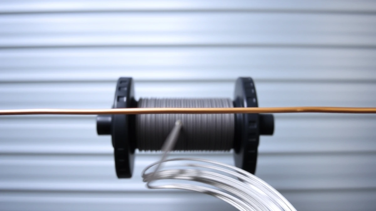
If voltage shapes the arc, wire feed speed supplies the current — and understanding this identity converts the feed dial from a volume knob into the machine’s most consequential control.
The mechanism: the arc must melt the wire arriving at a rate matching the feed. Faster feed = more metal per second = more current required to melt it (arc draws amps in proportion to the load presented). The empirical relationship on small flux core machines runs roughly in the ranges charts publish — commonly cited windows from ~100 ipm at the low end for thin-gauge work through 350–450+ ipm for heavy plate on capable machines — but the mapping from ipm to amps depends on wire diameter, stickout, voltage, and machine characteristics, which is why two machines at the same ipm can draw different amps. The practical takeaway: treat feed as your heat volume and voltage as your arc behavior — feed decides how much energy arrives per second, voltage decides how that energy distributes across the puddle.
Feed rate’s quality dimension is consistency. A steady feed produces a steady arc; a feed that hesitates — worn drive rolls, a draggy liner, kinked wire, a spool brake set too tight, a contact tip beginning to wear — modulates current randomly and produces exactly the erratic arc that welders then chase with voltage adjustments. The rule that prevents the misdiagnosis: verify the feed path before tuning electrical parameters. Straighten the gun and push the wire through (it should glide with light, even resistance), inspect the rolls (correct groove, no deep wear), check the tip bore (round, not oval), and free the spool (unwinding without drag spikes). Feed-path verification is step one of any systematic tuning session: our drive roll guide.
Feed also carries the thickness relationship: heavier material needs more total energy, delivered as higher feed (more amps) paired with higher voltage. The chart-based starting windows for common thicknesses live in our wire speed and voltage chart — but the numbers on any chart are entry points for the tuning loop, not answers. A welder who memorizes feed numbers without learning to read the puddle will still struggle on the day the material, the position, or the machine differs from the chart’s assumptions. A welder who can read the puddle can derive the numbers.
One honest warning about “amps” labels: on many 110V machines the dial marked amps isn’t directly measuring current — it’s commanding wire speed with an amps-style label because that’s what buyers expect. The number on the dial therefore won’t match a clamp meter’s reading on the work lead, and settings cards copied between machines can mislead badly. The portable truth: dial positions are machine-specific, weld puddles are physics-specific. Tune to the puddle on your machine and record what works — cards work when they’re annotated with stickout, position, and material assumptions, not just dial numbers.
The Voltage-Feed Pairing: Tuning Two Dials as One
Because voltage and feed are coupled through arc length and current, experienced welders don’t tune them as two separate decisions — they tune the pair against one observable: the puddle. The pairing logic runs like this: for a given thickness, set feed to the range that delivers adequate deposition and current (charts give the entry point), then dial voltage until the arc’s length and sound stabilize — if the arc stubs and pops, voltage is low for that feed; if it runs long and spattery, voltage is high. The pair is correct when the sound steadies, the puddle wets both toes, and the bead’s width-to-height ratio lands near the standard profile.
The pairing’s most common failure is asymmetric correction — moving one dial to fix a symptom the pair owns. Cold narrow bead: raise voltage? Sometimes — but if the underlying issue was feed too low for the thickness, voltage alone gives a hot narrow arc that underfills. Wide spattery bead: lower voltage? Or is feed too high for the machine’s capacity, driving excess current that voltage can’t tame? The disciplined method builds the test-bead loop: change one member of the pair, run three inches, evaluate sound-puddle-bead, change the next. It’s slower than guessing and immeasurably faster than dial-chasing — the structured version is taught in our settings guide, with the parameter theory behind it in this guide’s method section.
Thickness transitions expose the pairing most clearly. Moving from 1/8″ to 1/4″ plate isn’t one adjustment — it’s a coordinated climb: feed up (more amps for the mass), voltage up (arc length must grow with current to stay stable), possibly wire diameter up (if the machine’s feed range can’t deliver enough current on the thinner wire), stickout confirmed, angle confirmed. Each step re-opens the question “is the pair still right for what’s under the arc?” — which is why settings work on varied projects never fully ends, and why the ability to derive a window beats the ability to recall one. The full mapping from thickness to paired windows: our amperage chart and techniques masterclass.
Stickout: The Parameter You Never Dial
Contact tip-to-work distance is the parameter nobody thinks about and everybody violates — because it’s geometric rather than electrical, it changes without a click, and its electrical effect hides behind symptoms that look like settings problems.
The physics: wire conducts current from the contact tip to the arc; the longer the stretch, the more resistance heating occurs before the wire arrives — preheating it and lowering the current delivered at the arc. Empirically, extending stickout from 1/2″ to 1-1/2″ can drop effective amps by a double-digit percentage — the same dial settings, materially different arc. That’s why welders who “set the card” but hold inconsistent stickout across a session get inconsistent beads and blame the machine: the parameter moved, the numbers didn’t.
Stickout has two couplings worth memorizing. First, angle-stickout: tilting the gun pivots the tip relative to the work — a steep drag angle shortens stickout, a shallow angle lengthens it — so angle must be set first and stickout verified second, or your careful measurement describes a position you’ll immediately change. Second, stickout-voltage: because a longer stickout cools the arc, welders instinctively compensate with voltage — workable as a micro-adjustment, but a stickout correction is cleaner than a voltage offset, because voltage compensation leaves deposition behavior slightly off even when the arc looks right.
The working default for gasless flux core: 3/4″ to 1″ — long enough for puddle visibility and consistent preheat, short enough to keep effective amps in the chart’s window. Vertical and overhead work sometimes shorten it slightly for control; some heavy flat passes lengthen it deliberately for preheat — but every deviation is a choice that should be conscious and consistent, not drift. The habit that installs it: measure with a ruler once per session (against the gun at its working angle), commit the visual to memory, and re-check whenever the bead suddenly misbehaves after you’ve been welding in odd positions. Stickout’s diagnostic role appears in our troubleshooting playbook — as the variable checked before the dials, because it so often explains why the dials stopped working.
Polarity: Parameter Zero
Polarity isn’t a tuning variable — it’s the premise every other variable stands on. Self-shielded flux core wire’s classification, chemistry, and shielding behavior are all specified for DCEP (electrode positive): heat splits with roughly two-thirds concentrated at the wire (melting it efficiently at consumer-machine currents), the flux’s decomposition pathway runs as designed, and arc transfer behaves as the manufacturer tested it. Reverse the connection and every parameter window you’ve learned becomes invalid — the arc runs wild and unstable, the wire melts back at the contact tip, penetration collapses, spatter explodes, and no combination of voltage and feed produces a sound bead.
The cruel irony: wrong polarity produces symptoms that look like settings problems, which is why it tops the misdiagnosis list. A welder who has never verified polarity dials through every combination trying to fix an arc that has no fix — then concludes the wire is defective, the machine is weak, or flux core itself is unreliable. The correction costs nothing and takes seconds: follow the electrode lead to the positive terminal, read the panel switch, or run the test-bead comparison from our polarity guide. Build it into every session-start checklist alongside the feed-path check, and half the “mystery” arc problems in any shop disappear before they consume an evening.
Polarity also frames the process-boundary confusion: gas-shielded flux core and many MIG setups run DCEN — the reverse — so welders switching between processes must switch polarity with them, and machines built for one convention don’t always make the switch obvious. Multi-process machines often provide a panel toggle; single-process machines may be hard-wired. Know which you own before assuming the label means what a video implied — the labeling traps are catalogued in the polarity article, and the machines that handle switching gracefully appear in our machine deep dive.
With the primary electrical and geometric parameters defined, the guide now turns to the ones that live at the edges but shape results just as decisively — travel speed’s heat equation, machine and power-supply characteristics, and the position adjustments that tilt every window — before assembling the full tuning method.
Travel Speed: The Heat-Input Equation
Every other parameter sets what the arc offers; travel speed decides how much of that offer each inch of joint receives. The relationship formalizes as heat input — proportional to amps × volts ÷ travel speed (with process efficiency factors that rarely change the practical reading) — and it’s the parameter most often used to compensate for others, which is both its usefulness and its danger.
Double travel speed and each inch gets half the energy: the bead narrows, penetration flattens, and on thick material the weld fails to fuse its own root. Halve the speed and each inch gets double: the puddle floods, burns through thin work, widens beyond the joint, and dumps distortion into the plate. The correct speed is defined by puddle geometry rather than a number — the molten pool’s leading edge riding just ahead of the arc, wicking both toes, holding consistent width. When the puddle’s heel starts lagging behind the arc, you’re too slow; when the puddle’s edge races ahead and the bead narrows, you’re too fast. Consistency matters as much as the value: a bead that varies in width through its length is reporting speed variation (or angle variation — the two drift together when body position is poor), and inconsistent heat input means inconsistent properties along a seam that has to perform uniformly.
Speed’s interaction with the pair deserves attention: raising thickness requires more energy, which arrives as higher feed and voltage — but only if speed holds. A welder who scales settings up while simultaneously slowing down (a natural instinct, letting the puddle “catch up”) double-counts the correction and overloads the joint. The disciplined method: set the pair for the material, then adjust speed until the puddle geometry is right, watching for the failure modes — under-wetting at speed (raise energy or slow down), flooding at slowness (trim energy or speed up). Where the practice drills for speed discipline live: our home practice guide.
Speed also determines distortion behavior on thin material — the practical reason stitch technique exists. Short segments at brisk speed, with cooling gaps between them, keep peak temperature localized and let the plate shed heat before the next segment loads it. The alternative — one continuous slow pass — soaks the sheet with energy per inch and warps it out of dimension. Thin-material heat management has its own playbook in our thin metal guide, and the speed parameter inside it is the same equation, applied with intent.
Machine and Power Parameters: What Happens Behind the Dial
Parameters don’t stop at the gun — the machine’s own characteristics and the power feeding it shape what the dials can deliver, and these upstream variables explain a meaningful share of “my settings stopped working” mysteries.
Input voltage quality is the biggest upstream factor for small machines. A welder rated 140A at 120V expects full wall power; fifty feet of undersized extension cord delivers 105V instead, and the machine’s maximum output falls with it — settings that achieved a stable arc on a short lead go cold and stubbing on the long one, with zero indication on the dials. The fix is sizing (cord gauge matched to the draw over the actual run — our breaker and cord sizing guide has the tables), and the diagnostic is simple: weld at the machine, same settings, short lead — if the arc transforms, the problem was never the parameters.
Duty cycle is the time-domain parameter: the fraction of a ten-minute window the machine can weld at rated output before thermal protection kicks in. A 20% duty cycle at 180A means two minutes of arc, eight of cooling — and a machine pushed past its rating doesn’t fail dramatically; it degrades, throttling output mid-pass and destabilizing the arc in ways that mimic settings faults. Work planning that respects duty cycle (segmented passes, natural cooling breaks during fit-up and cleaning) keeps the machine inside its window: our duty cycle guide.
Waveform and arc-control features on modern inverter machines — adjustable inductance, arc stiffness settings, “crisp/soft” modes — are genuine parameters, and they do what they claim: inductance shapes how fast current rises during each short-circuit cycle, which changes puddle character. Lower inductance: stiffer, more directed arc, smaller puddle — useful on thin sheet and vertical-up where puddle size must stay contained. Higher inductance: softer, more fluid arc, better wetting — useful on flat heavier passes where puddle flow helps toes wet. The setting is a refinement applied after the voltage-feed pair is correct — it adjusts arc character within a working window rather than fixing a broken one. Machines offering this control: our beginner and mid-tier machine reviews. Machines without it (most entry-level units) rely entirely on voltage, feed, and stickout — which remain sufficient for sound work.
Machine output class sets the outer boundary: a 140A machine physically cannot produce the current window that 1/2″-plate settings demand, and no dial technique changes that. Honest capability assessment — matching project thickness to machine rating, using multi-pass strategy where single-pass capacity ends — prevents the frustration cycle where welders chase settings their hardware can’t reach: our machine deep dive explains output ratings and what they mean in practice.
Position Adjustments: The Window Tilts
Flat-position settings are the baseline every chart assumes — and out-of-position work modifies the whole window in coordinated ways, because gravity now competes with surface tension for control of the puddle.
Horizontal (weld axis horizontal, puddle held against gravity’s cross-pull): trim the flat window down — typically 5–15% on both voltage and feed — and bias the work angle slightly toward the upper plate so heat splits evenly across the joint despite gravity pulling the puddle toward the lower member. The signature horizontal defects (cold rolled upper toe, sag on the lower side, asymmetrical fillet) trace directly to uncorrected flat settings: the puddle that sat comfortably in flat runs wants to slump sideways, and a slightly smaller, slightly cooler puddle with the right work angle holds its geometry. Full horizontal treatment: our horizontal settings guide.
Vertical-up climbs against gravity with the puddle shelving on its own solidified metal — the position where parameter discipline matters most. Settings trim down (the puddle must stay small enough to be supported), travel angle steepens into a committed trailing drag, and the weave’s pause-at-toe rhythm controls heat distribution across the joint. Too much energy in vertical-up and the puddle sags or drops; too little and the toes don’t wet as the arc climbs. The window and technique pair: our vertical-up settings guide.
Overhead demands the lowest heat of any position (puddle mass must stay minimal to hang), disciplined stringers rather than weaves, and often a slightly shortened stickout for arc stability. The parameter trim runs deepest here — commonly 10–20% below flat — paired with the most committed travel speed, because hesitation lets puddle mass accumulate until gravity wins. Safety context for the position (falling spatter, PPE coverage): our welding safety guide.
The unifying principle: position modifies the window; it doesn’t invalidate the method. Start from the flat chart, trim per position, then run the same test-bead tuning loop with the same instruments — because the puddle’s language (sound, wetting, profile) stays constant while the numbers that produce it shift. Welders who carry this method between positions stop needing a separate chart for every orientation, which is the whole point of understanding parameters instead of memorizing them.
Starting Windows: The Master Parameter Tables
Consolidating the theory into practical entry points — the numbers a tuning session starts from for self-shielded flux core on a capable machine, flat position unless noted. Treat every cell as the midpoint of a window, adjust per the method section, and annotate whatever you discover about your own machine’s behavior.
| Thickness |
Wire |
Voltage |
Feed (ipm) |
Stickout |
Notes |
| 20–22 ga |
.030″ |
15–17 |
80–130 |
3/4″ |
Stitch technique; heat control dominates |
| 16–18 ga |
.030″ |
16–18 |
120–170 |
3/4″–1″ |
Single pass; watch distortion |
| 1/8″ |
.030/.035″ |
17–19 |
150–210 |
3/4″–1″ |
General repair core window |
| 3/16″ |
.035″ |
18–21 |
180–260 |
3/4″–1″ |
Flat fillets single pass |
| 1/4″ |
.035″ |
21–24 |
250–350 |
3/4″–1″ |
Bevel + multi-pass typical |
| 3/8″+ |
.035″ |
22–26 |
300–450 |
1″ |
Multi-pass; verify machine capacity |
The position-correction table applies multiplicatively to the pair:
| Position |
Voltage vs Flat |
Feed vs Flat |
Technique Modifier |
Signature Risk If Uncorrected |
| Flat (1F/1G) |
Baseline |
Baseline |
Drag 10–15°, standard work angle |
— |
| Horizontal (2F) |
−5 to −12% |
−5 to −12% |
Work angle biased slightly to upper plate |
Cold upper toe; lower-side sag |
| Vertical-up (3F/3G) |
−5 to −15% |
−8 to −15% |
Steeper drag; weave pause at toes; segment passes |
Puddle sag; uneven toes; stacked defects |
| Overhead (4F/4G) |
−10 to −20% |
−10 to −20% |
Stringers only; committed speed; minimal puddle |
Puddle drop; spatter fall; uneven fusion |
Read the tables as a launch sequence: pick thickness row → apply position modifier → confirm polarity and stickout → test bead → tune the pair with one-variable moves → weld. The same sequence scales from a 16-gauge patch to a multi-pass plate joint, and the annotated records it produces become a card worth keeping — because unlike Roy’s, this one carries its assumptions with the numbers. Broader chart context: our wire speed and voltage chart.
The Tuning Method: A Systematic Session Protocol
Parameters become mastery through method, not memorization — and the method that consistently outperforms intuition has seven steps, run in order, every session, without skipping ahead.
Step one — system verification. Polarity DCEP (terminal check), feed path healthy (push test through straightened gun, roll and tip inspection), wire dry and correctly sized, ground clamp clean and placed near the work, input power adequate (right outlet, right cord). None of these are tuning — they’re premise checks, and running them first means every subsequent observation describes your parameters rather than a hidden fault. Session-start checklist source: our costly mistakes guide.
Step two — set geometry. Gun angle (drag 10–15°), work angle for the joint, then measure stickout to 3/4″–1″. Geometry before dials, because both the dials’ meaning and your ability to hold the gun depend on the physical setup being fixed first.
Step three — set the window from the tables. Thickness row, position modifier, both dials to the adjusted midpoint. This is where charts belong: informing the start, never replacing the observation.
Step four — run the instrument test bead. Three inches on matching material (not heavy scrap, not the actual joint yet). Evaluate the three instruments: sound (steady crackle vs stubbing pop vs long hiss), puddle (fluid, following arc, wetting both toes, correct size for position), bead after slag removal (even ripples, standard width-to-height ratio, tied toes, no pinholes). The instruments speak a language independent of machine brand — fluency in that language is the actual skill: our beginner tips.
Step five — one-variable moves. Cold and narrow with stubbing sound → voltage up first. Hot, wide, spattery → voltage down, then check feed isn’t over-range. Puddle too large for position → both down. Deposition too slow for thickness → feed up, re-check voltage pairing. Move, re-test, evaluate — never two dials between observations, because two moves leave you unable to say which one worked.
Step six — lock and annotate. When the instruments are right, write the dial positions with their context (material, thickness, position, stickout, wire) — the annotation is what makes a settings record portable and honest. Machine-specific cards are gold when annotated; misleading when bare.
Step seven — weld the joint with monitoring. The parameters hold only while the geometry and context hold — stickout drifts through awkward positions, wind changes, the material’s thickness varies mid-joint (frame rails and exhaust never cooperate). Periodic re-checks during long sessions — sound hasn’t changed, bead width hasn’t wandered — convert tuning from a setup event into a continuous discipline. When a weld suddenly misbehaves mid-session, run the diagnostic order in the next section before touching a dial: our troubleshooting playbook formalizes the sequence.
Parameter Drift Diagnosis: Which Variable Moved?
A bead that suddenly misbehaves has a cause, and the causes have shapes — recognizable symptom patterns that point at the parameter that actually moved, even when no dial was touched. The table is the diagnostic shortcut:
| Symptom Change |
First Suspect |
Second Suspect |
Confirming Test |
| Arc goes cold/stubby with settings unchanged |
Stickout lengthened (angle drift) |
Input voltage sag (cord/outlet) |
Measure stickout; weld at machine on short cord |
| Arc gets wild, wire melts back at tip |
Polarity reversed (switch/terminals changed) |
Feed-path fault (tip bore worn) |
Terminal check; inspect contact tip |
| Bead narrows and stiffens mid-session |
Travel speed increased (fatigue/rhythm) |
Feed drifted down (roll tension) |
Watch puddle at fixed reference; check dial position |
| Porosity appears after earlier clean welds |
Wind shifted; plume redirected |
New spool is damp; joint zone contaminated |
Check environment; swap spool; re-clean joint |
| Spatter rises gradually |
Contact tip bore worn oval |
Voltage creep low relative to feed |
Replace tip; re-run instrument test |
| Bead inconsistent pass to pass |
Feed resistance varies (liner/kinks/spool drag) |
Body position varying angle through passes |
Push test; film your gun hand; re-set angle each restart |
| Arc weakens as the job goes on |
Thermal rollback (duty cycle exceeded) |
Ground clamp connection heating (poor contact) |
Let machine rest; check clamp and work-lead connections |
| Undercut appears in an established rhythm |
Voltage high for the position |
Travel angle steepened without noticing |
Instrument test at original settings; check angle |
Two disciplines make the table reliable. Change one thing — diagnose against the prior known-good state, one suspect at a time, so each test has one interpretation. And prefer geometry checks before dial checks — stickout, angle, speed, and environment are the variables that move without anyone deciding to move them, while dials sit still unless deliberately turned. The habit inverts the beginner’s instinct (grab the dial first) and resolves a larger share of real-world parameter problems per session, because in practice it’s usually the un-dialed variable that broke: the tips collection covers the monitoring habits that catch drift early.
Context Parameters: Material, Joint, and Environment
The final tier sets where the windows live before any tuning begins — the contextual parameters that explain why “correct” settings from one job misbehave on the next.
Material does double duty as heat sink and chemistry. Thicker sections absorb heat faster (needing more total energy), and alloy or coating changes alter puddle behavior: galvanized surfaces inject zinc into the arc (disturbing transfer and contaminating the weld — grinding back the coating is a parameter-level decision, not just prep: our galvanized guide), while rusty mill-scaled steel changes arc stability across the pass. Heat capacity also runs the thin-metal equation in reverse — thin work punishes every excess amp immediately, pushing windows down and technique toward stitch discipline: our thin metal guide.
Joint geometry decides the energy split — butt, fillet, lap, corner, and open-root joints each want heat directed differently (that’s work angle’s job), and fit-up gaps change deposition demand: an open root needs lower heat and precise puddle placement to avoid dropping through, while a tight beveled groove accepts higher energy with multi-pass strategy. Fit-up and sequence planning belong to parameter-setting because they define what the parameters must accomplish: our joint technique tips.
Environment — wind, temperature, position of the work itself — enters through shielding and heat-loss pathways. Wind displaces the flux-generated atmosphere (shelter before compensation — no voltage adjustment fixes an evacuated shield), damp surfaces load the puddle with hydrogen (dry the joint zone), and cold ambient steel pulls heat faster (a modest upward nudge to the window, applied after shelter and dryness are handled). Fume management rides along: gasless parameters that work outdoors vent naturally, while indoor sessions need the ventilation discipline from our welding fumes guide.
Stack the three tiers — system premises, geometric settings, contextual windows — and every “what should I set?” question decomposes into answerable pieces. That decomposition is the difference between a craft controlled by its practitioner and one at the mercy of whichever card is taped inside the cabinet door.
Parameters in Professional Practice: From Dial Numbers to Qualified Procedures
Everything in this guide happens at the welder’s level of the craft — the test beads, the instrument readings, the one-variable moves. It’s worth knowing how the same parameter thinking scales up into industrial practice, because the professional framework is the same logic with documentation attached, and understanding it sharpens the home-shop method rather than being a separate religion.
In qualified welding work — structural steel, pressure vessel, pipeline, heavy fabrication — the parameter set becomes a Welding Procedure Specification (WPS): a written document that pins down the variables this guide treats as a system. The WPS specifies filler classification, diameter, polarity, voltage and current ranges, travel speed bounds, position, shielding (including gas flow where applicable), preheat requirements, and joint preparation — essentially a formalized version of the “annotated card” discipline, but with each value justified by a supporting procedure qualification record (PQR): test results proving the specified parameters produce welds meeting the required mechanical properties. The point isn’t bureaucracy for its own sake — it’s traceability. When a parameter is qualified, anyone running the procedure within its windows produces acceptable work; deviations become documentable events rather than invisible risks. The standards framework governing this machinery in the United States is the American Welding Society’s — AWS D1.1 for structural steel welding, with filler metal specifications (the A5 series that classifies your flux core wire) sitting alongside it: AWS standards catalog. For a home-shop welder, the takeaway isn’t to write a WPS for the garage — it’s to borrow the mindset: write down your qualified parameters, with their assumptions, and treat deviations as deliberate decisions.
The technical literature behind those procedures reads like this guide’s footnotes. Research bodies have spent decades mapping the parameter relationships we’ve discussed from first principles: arc physics and metal transfer behavior, shielding gas and flux chemistry interactions, heat input’s effect on weld metal microstructure and mechanical properties, and the defect mechanisms that arise when parameters leave their windows. TWI (The Welding Institute) maintains one of the world’s deepest technical archives on exactly these questions — their publications on tubular wire welding, heat input control, and defect diagnosis are the deep-water sources behind the practical rules quoted throughout this article. The historical arc of the process itself — from coated electrodes through solid wire to tubular consumables — is sketched in Encyclopaedia Britannica’s welding overview, useful context for understanding why flux core’s parameter set looks the way it does: the consumable was engineered around field shielding constraints, and its parameters follow from that design brief.
Machine manufacturers sit between the research and the welder, translating parameter science into equipment behavior and reference material. Manufacturer technical libraries — Miller Electric’s resources and Lincoln Electric’s technical references among them — publish parameter starting charts, application bulletins, and technique notes calibrated to their machines’ characteristics; when a manufacturer’s chart differs slightly from another’s, it usually reflects waveform design, feed calibration, or the assumptions annotated (or missing) around the numbers. Reading those charts as starting windows with a stated machine context — rather than universal truths — is exactly the literacy this guide exists to build.
Safety parameters complete the professional set, and they’re the ones no procedure is allowed to skip. Ventilation rates, exposure limits, respiratory protection requirements, electrical safety practices, and fire-watch discipline are parameters of the environment around the arc — as real as voltage, and enforced with considerably more force. The regulatory floor in the United States comes from OSHA’s welding, cutting, and brazing standard, with the occupational health research — including the exposure science behind why flux core’s higher fume output deserves engineering controls — from NIOSH’s welding program. Our welding safety guide and welding fumes guide translate those parameters into shop practice: the extractor that runs, the respirator that fits, the breaker sized for the draw, the fire watch that stays until the last ember. A parameter set that produces beautiful beads in an unventilated space hasn’t succeeded — it has failed at the requirement that outranks all the others.
The bridge between garage practice and professional procedure, then, is a habit rather than a certificate: document the window, justify it with evidence, monitor the deviations. Test beads are your PQR; your annotated settings card is your WPS; the instrument checks are your inspection regime. Scaled honestly, the same method that qualifies a structural procedure runs a Saturday repair — and welds made with that discipline carry a consistency that luck never will.
Two Worked Examples: Deriving Settings From Zero
Theory proves itself in derivation — so close the method with two full walkthroughs, each starting from nothing but a job description and ending at weld-ready parameters. The first: a 1/8″ mild steel bracket, flat position, 110V machine, fresh setup. Premises first: polarity confirmed DCEP at the terminals, .030″ wire loaded (the 140A machine’s natural diameter), feed path push-tested, joint ground bright within an inch, ground clamp biting clean metal beside the work. Geometry: drag set at 12° with a protractor card (calibrating the eye), work angle bisecting the fillet, stickout measured to 3/4″ after the angle locked. Window: thickness row for 1/8″ says roughly 17–19V at 150–210 ipm flat — set 18V and 180 ipm as the midpoint, run three inches on matching scrap. The instrument read: sound was steady but the puddle ran slightly shy at the toes — one-variable move, voltage to 18.5V (feed untouched), re-test — toes now wetted, ripples even, width consistent. Lock, annotate (“.030, 1/8 flat, 18.5V/180ipm, 3/4″ stickout”), weld the bracket. Total derivation: two test beads and about four minutes, with every observation attributable to exactly one change.
The second: a horizontal fillet on 3/16″ plate, same machine now on 220V, .035″ wire — the context switch. New wire diameter means re-checking the rolls (swapped to .035 profile, tension reset) and a new premise pass — polarity still DCEP, liner still passing the push test, stickout re-measured at the new angle after the horizontal gun position changed the pivot. Window derivation: flat row for 3/16″ suggests 18–21V at 180–260 ipm, then the horizontal modifier trims 5–12% — start at 19V and 220 ipm, biased slightly down from flat midpoint. Geometry adds the horizontal-specific work angle (slight bias toward the upper plate to counter gravity’s pull across the joint). Test bead on 3/16″ scrap in the horizontal fixture: sound steady, puddle stable, but the upper toe ran marginally cold — the classic horizontal signature. The fix isn’t voltage (the pair was set for the thickness) — it’s the work angle, nudged a few degrees toward the upper plate, re-tested, resolved. Lock and annotate with the position noted (“horizontal, 3/16, .035, 19V/220ipm, +upper bias”) — the annotation is what makes the record honest for next time, because the same dial numbers in flat would produce a different bead.
Both derivations share the skeleton: premises → geometry → window → test → one-variable moves → lock and annotate. Notice what never appeared — guessing, memory of “the numbers that always work,” or a dial grab in response to a symptom with multiple possible causes. The method is slower than superstition the first ten times and faster than superstition forever after, because every session that follows starts from a documented, justified window instead of a fresh experiment. That compounding is what parameter literacy actually buys: not a better chart, but the retirement of charts as a source of uncertainty.
Frequently Asked Questions
What are flux core welding parameters?
They’re every variable that governs the arc and the deposited weld: the electrical set (voltage, wire feed speed/amperage, polarity), the geometric set (stickout, travel angle, work angle, travel speed), and the contextual set (wire diameter, material thickness and condition, joint geometry, position, shielding environment, machine and power characteristics). Parameters form a coupled system — each one changes what the others mean — which is why sound practice treats them as a set to be tuned together against observable puddle behavior, not as isolated dial readings: our settings guide.
Should I adjust wire speed or voltage first?
Set wire feed first — it determines your amperage and deposition for the thickness — then dial voltage to stabilize arc length and puddle behavior at that feed. The pair must climb together as material gets heavier (more feed needs more voltage; more voltage without feed gives a long hot arc that underfills). The symptom-driven version: cold narrow bead with stubbing → feed may be low (or voltage low for the current feed); wide spattery bead → voltage high or feed over-range. The full pairing logic: the voltage-feed section above and our wire speed chart.
My machine has an “Amps” dial — is that really amps?
On most consumer flux core machines, no — the dial commands wire feed speed with an amps-style label, because feed is what actually controls current on a constant-voltage machine. The practical consequence: dial numbers don’t transfer between machines (a “100” on one welder isn’t another’s “100”), and clamp-meter readings won’t match dial labels. Tune to puddle behavior on your machine and annotate what works with context: the wire-feed-as-amperage section above.
What exact stickout should I use?
Three-quarters of an inch to one inch for general gasless flux core work — the range where preheat and effective current match chart assumptions and puddle visibility stays good. Set gun angle first (tilting pivots the tip-to-work distance), then measure stickout second, then weld — and re-check whenever you’ve been working in awkward positions. Longer stickout lowers arc current (more preheat), shorter raises it — both move your window without touching a dial: the stickout section above and our techniques masterclass.
How much should I trim settings for vertical-up?
Start 5–15% below the flat window on both voltage and feed, then tune by test bead — the puddle must stay small enough to be supported as it climbs, and the exact trim depends on thickness, weave style, and machine. Horizontal trims similarly (5–12%), overhead deepest (10–20%). Position-specific tables and technique pairings: our vertical-up and horizontal settings guides.
What does the inductance knob on my machine do?
Inductance controls how fast current rises through each short-circuit cycle — shaping arc character rather than arc energy. Low inductance: stiffer, more directed arc with a smaller, tighter puddle (useful on thin sheet and vertical work). High inductance: softer, more fluid arc with better wetting (useful on flat heavier passes). It refines a working voltage-feed pair — it doesn’t fix a broken one — so set the pair first, then use inductance for puddle feel. Machines with adjustable arc control: our machine reviews.
Why do my usual settings suddenly weld badly?
Because something in the system moved — and it’s usually not a dial. Run the diagnostic order: check stickout (angle drift lengthens it), polarity (switches get bumped), feed path (tip bore wear, liner drag), input power (cord, outlet, breaker sharing), environment (wind, damp material, different steel), then position and technique drift. Only after the premise checks pass should the dials be revisited. The full drift-diagnosis table above covers the symptom-to-cause mapping: our troubleshooting playbook.
Can I copy settings from another welder’s chart?
As a starting hypothesis, yes; as an answer, no — because dial-to-output mapping varies by machine (waveform, feed calibration, rating), and charts silently assume stickout, position, and material conditions that may not match yours. The portable practice: start from the other chart’s window, run your own instrument test, and annotate your machine’s actual numbers with context. Machines’ behavior and differences are surveyed in our machine deep dive.
Does my wall outlet affect my settings?
Yes — input voltage directly limits machine output. An undersized extension cord or shared circuit delivering less than rated voltage means the machine can’t reach the current your settings assume: the arc goes cold and stubby with dials unchanged. Weld at the machine on a short, correctly-sized cord as a test; if the arc transforms, the parameters were fine and the power feed was not. Sizing tables: our breaker sizing guide.
What’s the fastest way to dial in a new material?
The seven-step session: verify premises (polarity, feed, wire), set geometry (angle, stickout), set the window from the thickness table with position modifier, run a three-inch instrument test, move one variable per re-test, lock and annotate when sound/puddle/bead converge, then weld with periodic re-checks. It typically converges in two to four test beads — faster than guessing because each observation has exactly one interpretation. The method section above walks each step; practice structure: our home practice guide.
The working formula: heat input is proportional to (voltage × amps) ÷ travel speed, scaled by a process efficiency factor (flux core’s commonly taken around 0.8 for practical comparisons). Example: 19V at 180A traveling 10 inches per minute delivers roughly (19 × 180 × 0.8) ÷ 10 ≈ 274 joules per millimeter-equivalent territory — you don’t need the absolute number so much as the relationships: double speed and each inch gets half the energy; raise current 20% and the plate sees 20% more. Clamps meters measure the current side directly, and travel speed can be timed over a known distance — both worth doing once so the arithmetic becomes intuition. Why it matters practically: heat input governs distortion, penetration, and grain structure — our weld strength analysis and thin metal guide both run on this equation underneath.
The System Behind the Dial
Roy retired his card — not because numbers stopped mattering, but because he finally understood what they always were: snapshots of a system, valid only where the system’s assumptions held. What replaced the card lives in his hands now: polarity checked before anything else, geometry set before dials, windows derived from thickness and position, and the three instruments — sound, puddle, bead — consulted after every test bead like readings on a dashboard. When the 16-gauge fender patch arrived at that awkward upward angle in the driveway wind, he didn’t need a chart. He needed shelter for the puddle, .030″ wire, DCEP confirmed, stickout measured at the steeper angle the position demanded, the flat window trimmed toward vertical, and two test beads worth of patience. The welds came out right — not because he’d memorized the right numbers, but because he knew which questions to ask before any number could mean anything.
That’s the parameter system in full: voltage that shapes the arc, feed that carries the current, stickout that quietly moves the window, polarity that makes every other reading meaningful, angle and speed that decide where the energy lands, and context that sets where all of them live. Tune them one at a time, verify the premises before blaming the dials, and let the puddle — always the puddle — have the final vote. Do that consistently, and no material, position, machine, or weather condition will ever catch you without an answer, because the answer was never on a card. It’s in the system, and the system now belongs to you.