MIG Basics: The Complete Beginner’s Guide to MIG Welding (Setup, Settings & Technique)
Learn MIG basics from scratch: how GMAW works, machine setup, wire and gas choices, transfer modes, technique, troubleshooting…
READ ARTICLE →The phone rang on a Saturday morning, and a friend asked if I could look at his aluminum boat trailer. One of the crossmembers had cracked clean through after two summers of salt water and potholes. He had already been told by a shop that the job would cost more than the trailer was worth, and another welder had turned it away because he “didn’t do aluminum.” So the trailer sat in a driveway, and the boat sat on blocks. I told him to bring it over, because the answer to the question everyone eventually asks is simpler than the internet makes it sound.
Can you weld aluminum with a MIG welder? Yes, you absolutely can. It is not a myth, it is not a hack, and it is not reserved for people with ten-thousand-dollar machines. But aluminum is not steel, and the difference is not cosmetic. Aluminum demands a different gas, a different wire, a different way of feeding that wire, and a different attitude toward cleanliness. Get those four things right and MIG welding aluminum becomes a repeatable, useful skill. Get them wrong and you will chase porosity, bird-nesting, burn-through, and a trail of ugly beads that break when you look at them funny.
This guide walks you through the whole thing from the ground up: why aluminum behaves the way it does, exactly what equipment you need, how to set your machine, how to move the gun, what to do when something goes wrong, and how MIG compares with TIG and the other options on the table. Whether you are fixing a trailer, building a bumper, or repairing a cast bracket in the garage, you will find the practical answers here.
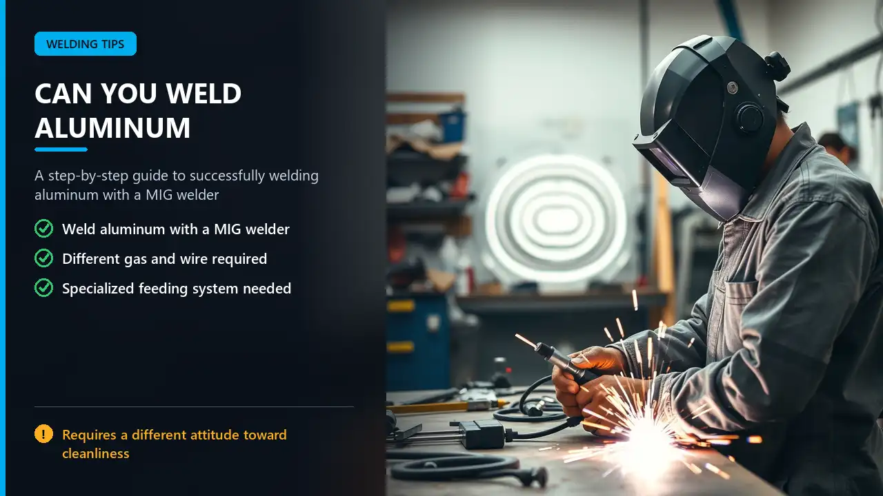
Yes, you can weld aluminum with a MIG welder, provided your machine can run on direct current electrode positive (DCEP) polarity and you invest in the right feeding setup. The single biggest obstacle is not arc stability, it is wire feed: aluminum wire is soft and gummy, and it drags inside a standard steel liner. That is why spool guns and push-pull systems exist. Beyond feeding, you need 100 percent argon shielding gas (never CO2, never an argon/CO2 mix), clean aluminum that has been wire-brushed with a dedicated stainless brush, and the right filler alloy — ER4043 for general work and better puddle flow, ER5356 for higher strength and anodized finishes. Expect to run faster travel speeds and higher wire-feed settings than you would on steel of the same thickness, and expect to push rather than pull the gun. MIG is the fastest, most forgiving way to join aluminum thicker than about 1.5 mm (around 16 gauge), while TIG still wins for thin sheet, cosmetic work, and precision. The rest of this article covers setup, settings tables, technique, common mistakes, troubleshooting, and safety in full detail.
To understand why aluminum MIG welding earns its reputation, it helps to know what the metal is doing underneath the arc. Three properties cause almost every problem beginners run into.

Every piece of aluminum is coated in aluminum oxide the instant it touches air. The layer is thin enough to ignore by eye, but it melts at roughly 2,070°C (3,760°F), while the aluminum underneath melts at about 660°C (1,220°F). That is a staggering gap — the skin on your metal will still be solid when the base metal has already turned to soup. Steel does not work this way; iron oxide melts at roughly the same temperature as the steel itself, so the arc tears right through it. With aluminum, the oxide has to be removed mechanically before welding or the arc will wander, the puddle will refuse to wet out, and you will get an erratic, spattery mess that looks nothing like a real weld.
This is why a stainless steel wire brush used only on aluminum is non-negotiable, and why solvent cleaning alone is not enough. It is also why you never grind aluminum with a wheel that has touched steel — embedded iron particles will contaminate the surface and later cause rust staining and weak welds. For a deeper dive into the chemistry behind this, ASM International publishes extensive reference material on aluminum metallurgy and surface behavior.
Aluminum conducts heat roughly four times better than carbon steel. When you strike an arc, the heat does not stay put — it races away from the joint in every direction. Two things happen as a result. First, the metal around the weld gets hot fast even though the puddle itself looks cold, so you can burn a hole through thin material before your eyes have caught up. Second, when you stop, the puddle loses support and collapses instead of freezing neatly. You end up with craters at the end of every bead, and craters are where cracks start.
The practical implication is simple: travel faster than feels natural, use more amperage than you expect, and keep the arc aimed into the puddle. On thicker sections, a modest preheat of 70–100°C (150–200°F) helps even out the temperature and slows the cooling enough to avoid cracking, particularly on heavy castings and 6xxx-series alloys. Do not preheat thin sheet; it will simply melt away. The U.S. Department of Energy’s lightweight materials program has documented how thermal management drives nearly every joining decision in modern aluminum-intensive vehicle structures.
When steel is molten it glows — orange, then cherry red, then bright yellow — so you can read temperature directly from the color. Molten aluminum does not glow at all until it is already far past its melting point. It looks like a shiny, trembling puddle of wet foil, and then without warning it goes transparent and drops out of the joint. Experienced aluminum welders describe it as watching a mirror that suddenly disappears. The lesson is to watch the leading edge of the puddle and the fillet shape, not the color, and to keep moving.
MIG — officially gas metal arc welding, or GMAW — feeds a consumable wire electrode through a handheld gun. The wire makes electrical contact inside the gun at the contact tip, arcs to the workpiece, melts, and becomes the filler metal. At the same time, a shielding gas flows out of the nozzle around the arc to keep oxygen and nitrogen away from the molten pool. The process on aluminum is exactly the same as on steel in principle. All of the differences live in the details.
On steel, the wire feeds through a long liner from a drive roll at the machine, sometimes three or four meters away, and it feeds fine because steel wire is stiff and slippery. Aluminum wire is soft and sticky — the alloy grabs the inside of the conduit and the bends in the gun cable add friction with every millimeter. Feed it through a standard steel liner and you get slack in the line, then a nest of tangled wire, then a bird’s nest that jams the drive rolls and stops the weld mid-bead. Everything in the aluminum MIG setup is designed to solve that one problem.
The electrical setup matters too. Aluminum MIG runs on direct current electrode positive, meaning the gun lead is positive and the work clamp is negative. In this polarity, about two-thirds of the arc energy is concentrated at the wire tip, which gives the clean, stable spray transfer that aluminum needs. Polarity is one of those settings people overlook when they switch processes, and it changes everything about how the arc behaves. If you want the underlying theory, our guide to MIG polarity explained walks through what DCEP and DCEN each do to penetration and deposition.
You can retrofit almost any decent MIG welder for aluminum without buying a new machine. Here is the complete list, in the order you will use it.
| Component | What to Use for Aluminum | Why It Matters |
|---|---|---|
| Welding machine | MIG welder capable of DCEP, with enough output (roughly 150 A+ for 14 ga and heavier) | Aluminum needs more current than steel at the same thickness because heat runs away so fast |
| Wire feed method | Spool gun, push-pull gun, or a short smooth-lined spool-on-gun setup | Solves the soft-wire feeding problem that causes bird-nesting |
| Drive rolls | V-knurled or U-groove rolls sized to the wire, light nip | Knurled steel rolls dig into soft aluminum and deform it |
| Liner / conduit | Dedicated nylon or Teflon liner, replaced when switching back to steel | Steel liners have rough interior surfaces that shred aluminum wire |
| Contact tip | Correct bore for wire size, replaced regularly | A worn tip causes arcing inside the gun and erratic feed |
| Shielding gas | 100% argon, 15–20 CFH flow | CO2 and argon/CO2 mixes create unstable arcs and severe oxidation on aluminum |
| Wire | ER4043 or ER5356, 0.8–1.0 mm (0.030–0.040 in) | Wrong alloy cracks, wrong size feeds poorly or lacks penetration |
| Polarity | DCEP (electrode positive) | Required for spray transfer and a stable arc on aluminum |
| Cleaning tools | Stainless wire brush, acetone, clean white cloth, file | Removes the oxide layer and any oil that would poison the weld |
If your welder has an aluminum mode or a spool-gun trigger circuit already wired in, you are halfway there. If not, most machines have a two-pin or multi-pin DINSE-style accessory socket on the front panel specifically for a spool gun — check your manual before you buy anything. The broader machine-selection questions are covered in our wire feed welder guide, which explains what to look for in drive-roll quality and output range.
This is the decision that makes or breaks your aluminum MIG experience, so it deserves a proper comparison rather than a one-line answer. There are three realistic options, and each has a genuine place.
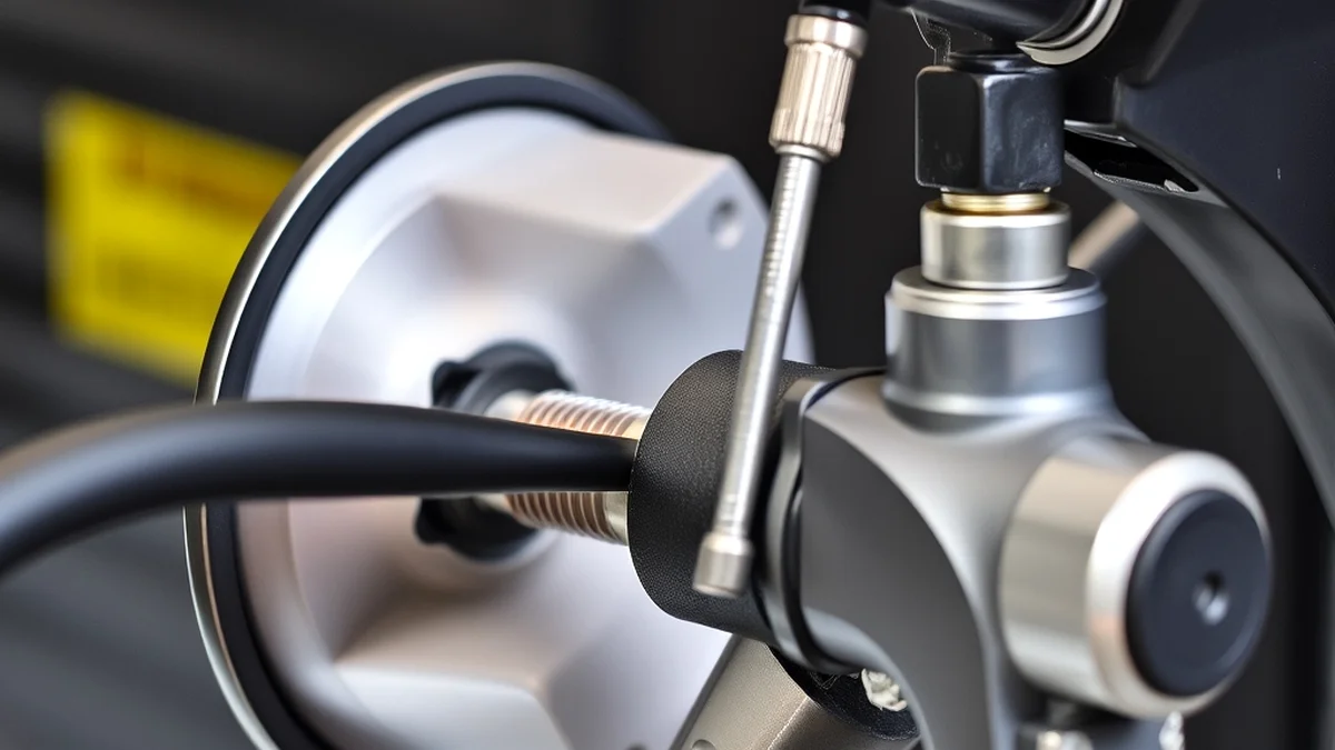
A spool gun is a standard MIG gun with a small 0.45 kg (1 lb) spool of aluminum wire mounted directly on top, plus its own motor and drive rolls. Because the distance from spool to contact tip is only a few hundred millimeters, the wire never has to fight friction through a long liner. Feeding problems essentially disappear. Spool guns are inexpensive relative to other options, work with almost any MIG welder that has a spool-gun circuit, and are perfect for occasional aluminum work — a few hours a month, a boat repair, a trailer fix, a set of brackets.
The downsides are real but manageable. One pound of wire does not go far on a long day, so you will change spools frequently. The gun is heavier and more front-heavy than a standard gun, which gets tiring on long beads. And the wire inside the spool can still tangle if you buy bargain-bin wire, because the spool’s internal tension is not adjustable the way a push-pull system is. Even so, for a hobbyist or a small shop that welds aluminum once in a while, the spool gun is the best value in the trade. If you are also wondering about welding cast parts, our piece on welding cast aluminum with a spool gun covers the extra prep castings require.
A push-pull system puts a second drive motor in the gun itself. The machine’s main drive rolls push the wire forward while the gun motor pulls it from behind, and the two motors are synchronized so the wire is under constant, gentle tension over the whole length. This is how production shops run aluminum: continuous 5–15 kg (10–33 lb) spools on the machine, comfortable standard-weight guns, and hours of uninterrupted feeding. If you weld aluminum daily, this is the system you want.
The cost is the main barrier. A quality push-pull gun can cost as much as a whole small MIG welder, and the machines that drive them usually have the synchronized motor electronics built in, so you may need to check compatibility before purchasing. If you are moving from occasional to regular aluminum work, it is the upgrade to plan for.
The budget option: keep your standard gun, remove the steel liner, and install a nylon or Teflon liner sized for aluminum, pulling it taut with almost no gap between the end of the liner and the contact tip. Some welders also remove the liner entirely on very short guns and run the wire through open space. It works, it costs very little, and many perfectly good aluminum welds have been made this way. The catch is that it only works reliably on shorter gun lengths and lighter wire diameters, and you must dedicate that liner to aluminum — swapping back and forth invites contamination. Treat it as a legitimate starting point, not a permanent solution.
| Feeding System | Approx. Cost | Wire Capacity | Best For | Watch Out For |
|---|---|---|---|---|
| Spool gun | Low–medium | 0.45 kg (1 lb) | Occasional use, repairs, hobby work | Front-heavy; frequent spool changes |
| Push-pull gun | High | 5–15 kg (10–33 lb) | Daily production, thick material, long beads | Machine compatibility; upfront price |
| Nylon/Teflon liner | Very low | Spool on machine | Short gun lengths, light wire, trial use | Only reliable on short runs; must be dedicated to aluminum |
| Standard steel liner | None | Spool on machine | Not recommended | Bird-nesting, shavings, inconsistent feed |
Once the wire source is sorted, the next weak link is the hardware between the drive rolls and the arc. Aluminum wire does not tolerate aggressive knurling. Standard V-knurled steel drive rolls, which bite hard into mild steel wire, will gouge and flatten aluminum, producing a shaved, flaky wire that jams in the contact tip. The correct choice is either a U-groove roll or a V-knurled roll made from a softer material, run with just enough nip to move the wire without crushing it. Set the tension by feel: pull the wire out of the gun by hand with the drive disengaged — it should slide with light resistance, not require a tug and not slide so freely that it falls out of its own weight.
The contact tip bore should be a close fit to the wire. A tip worn oval from long steel service will allow the wire to arc inside the gun, which causes popping, erratic current, and melted tip ends. Buy a handful of spare tips and change them the moment feed becomes inconsistent — a tip costs less than the wire you waste fighting a bad arc. Check the MIG wire size chart if you are unsure which diameter matches your material thickness, because oversize wire on thin aluminum is a fast route to burn-through.
Liners deserve the same attention. A steel liner that has been running mild steel wire for a year will contain fine oxidation and drawn-in dust that acts like sandpaper on aluminum. Fit a nylon liner, mark it clearly, and leave it alone. When you switch back to steel, fit a fresh steel liner rather than reusing the contaminated one. It is unglamorous maintenance, but it eliminates an entire category of feed problems before they start.

Gas selection is where many first-time aluminum welders unknowingly sabotage themselves, because the bottle they already own usually does not work. If your shop tank is the standard 75/25 argon/CO2 mix used for steel — and for most people it is — you cannot use it on aluminum. The carbon dioxide in that mix reacts violently with molten aluminum, breaking down in the arc and dumping carbon and oxygen into the puddle. The result is a black, crusty, porous weld that looks like a sponge and has the structural integrity of one. This is not a gray area: see our detailed look at welding aluminum with 75/25 gas for exactly what goes wrong.
Plain CO2 is even worse — it is a reactive gas, and on aluminum it produces an arc that will not run stably at all, heavy oxide film, and zero useful penetration profile. There is a reason every welding reference in existence lists CO2 as a steel-only gas. The shielding gas reference on Wikipedia lays out the reactive-versus-inert distinction clearly if you want the chemistry.
Use 100 percent pure argon. It is inert, it ionizes readily at the voltages MIG produces, and it gives the concentrated, directed spray transfer that makes aluminum MIG work. Flow rate should sit around 15–20 cubic feet per hour (roughly 7–9 litres per minute) for most bench work, with a slightly higher setting outdoors or near a draft. Too much gas is not a free upgrade — an over-strong flow creates turbulence that actually sucks atmospheric air into the puddle, producing porosity anyway. Start at 15 CFH, watch the weld, and adjust from there. Our guide to gas for aluminum welding covers tank selection, regulators, and hose considerations in more depth, and the MIG gas settings guide explains flow rates across processes.
Helium sometimes appears in the conversation. Argon/helium blends (typically 25–75 percent helium) run hotter, increase travel speed, and improve wetting on thick sections, but helium costs several times more than argon and is difficult to source consistently. Save the blend for a production environment where cycle time justifies the expense. For everything else, pure argon is correct, cheap, and available at any gas supplier.
MIG welding can run in either polarity depending on the process. Solid-wire MIG on steel runs DCEP, flux-cored welding usually runs direct current electrode negative (DCEN), and aluminum MIG must run DCEP — electrode positive, work negative. In DCEP, electrons flow from the workpiece up to the wire, and roughly two-thirds of the arc’s energy is released at the wire tip. That concentration melts the aluminum wire efficiently, stabilizes the arc, and produces the fine, penetrating spray of droplets the process needs.
Run aluminum on DCEN by accident and you get a soft, wandering arc that deposits metal with poor penetration and a chalky surface. It will not be obvious that polarity is wrong — the arc will strike and the wire will melt — so check your machine’s setting before you blame your technique. If you have recently been running flux core, this is the most likely trap, since flux-cored settings default to the opposite polarity. The MIG welding electrode overview gives a useful refresher on how the electrode circuit is completed.
| Parameter | Steel (MIG) | Aluminum (MIG) | What Happens If You Get It Wrong |
|---|---|---|---|
| Polarity | DCEP | DCEP (required) | DCEN gives a soft arc, poor penetration, unstable transfer |
| Shielding gas | 90/10 or 75/25 argon/CO2, or 100% argon | 100% argon only | CO2 causes gross porosity, oxidation, brittle welds |
| Liner | Steel | Nylon / Teflon, dedicated | Bird-nesting, shaved wire, feed surges |
| Drive rolls | V-knurled, firm nip | U-groove or soft knurl, light nip | Flattened, gouged wire that jams the tip |
| Transfer mode | Short circuit (most thicknesses) | Spray or globular-spray | Short circuit on aluminum gives cold laps and lack of fusion |
| Travel direction | Either (drag on heavy) | Push | Pulling traps gas and oxide ahead of the puddle |
The two alloys you will actually find on the shelf are ER4043 and ER5356. Both are valid aluminum MIG wires; they simply solve different problems. Choosing between them comes down to three questions: what is the base metal, is the weld visible, and does the part need strength or anodizing.
ER4043 is the general-purpose, easy-running choice. It contains about 5 percent silicon, which lowers the melting point, widens the freezing range, and lets the puddle flow and wet out beautifully. It resists cracking on most 6xxx-series alloys, tolerates a wider range of welding parameters, and produces a smooth, clean-looking bead with minimal fuss. It is also the wire to use on cast aluminum, because the silicon helps the puddle flow into the irregular, gas-rich surface of a casting. The trade-off: ER4043 is softer in the finished weld (its tensile strength is lower), it cannot be anodized to a matching finish because silicon does not take the dye, and it is a poor choice if the finished part will see high service temperatures.
ER5356 is the stronger, stiffer option. It contains about 5 percent magnesium, which gives it significantly higher as-welded strength and makes it the better structural choice for 5xxx-series bases and for parts that will carry load. It feeds slightly better because it is firmer, and — the reason many fabricators keep a spool handy — it anodizes to a color close to the parent metal, so on architectural and visible work it disappears. The downside is that it wets out less willingly than 4043, is more prone to hot cracking if used on the wrong base alloy, and develops a duller, slightly rougher bead surface. It is also less forgiving of a dirty joint.
| Property | ER4043 | ER5356 |
|---|---|---|
| Alloying element | ~5% silicon | ~5% magnesium |
| Puddle flow | Excellent — self-levels, forgiving | Stiffer — needs more deliberate manipulation |
| Crack resistance | Very good on 6xxx and castings | Good on 5xxx and 5356-matched work |
| As-welded strength | Lower (~190 MPa typical) | Higher (~240+ MPa typical) |
| Anodizing appearance | Turns dark grey — stands out | Matches base metal closely |
| Cast aluminum | Preferred | Not recommended |
| Best for | General repair, beginners, thin-to-medium sheet, visible cosmetic beads | Structural work, boat trailers, marine, architectural, 5xxx alloys |
| Feeding behavior | Softer — needs a well-set feed system | Firmer — feeds slightly easier |
A reasonable rule of thumb for someone starting out: buy a spool of ER4043 first. It is more forgiving of imperfect settings and technique, and it will let you learn puddle control without fighting the wire. Move to ER5356 when you have a structural reason to, or when appearance after anodizing matters. If you are joining aluminum to another metal entirely, filler selection gets more complicated — our article on welding aluminum to steel explains why a transition alloy or a mechanical joint is usually required, and the related piece on preventing galvanic corrosion covers what happens when the two metals stay in contact in a wet environment.
Wire diameter should match thickness. For sheet and light fabrication, 0.8 mm (0.030 in) wire gives excellent control and works down to about 1.5 mm material. For 3 mm and heavier, step up to 1.0 mm (0.040 in) so you can push more amperage without the wire burning back into the tip. General thickness-to-wire matching guidance for all processes is set out in our MIG wire size chart.
There is no single universal setting, because every machine’s dials mean slightly different things and each welder’s arc-length preference differs. But there are reliable starting windows, and starting in the right window is most of the battle. The tables below assume a typical constant-voltage MIG machine, DCEP, 100 percent argon, ER4043 wire, and a butt joint on clean material. Write down what works once you find it.
| Material Thickness | Wire Diameter | Wire Feed (approx.) | Voltage (approx.) | Notes |
|---|---|---|---|---|
| 1.5 mm (16 ga) | 0.8 mm (0.030 in) | 4–5 m/min (150–200 ipm) | 17–19 V | Watch for burn-through; travel briskly |
| 2.0 mm (14 ga) | 0.8 mm (0.030 in) | 5–6 m/min (200–250 ipm) | 19–21 V | Sweet spot for learning spray transfer |
| 2.7 mm (1/8 in) | 0.9–1.0 mm (0.035 in) | 6–7 m/min (250–300 ipm) | 21–23 V | Good range for trailers and framing |
| 3.2 mm (1/8 in+) | 1.0 mm (0.040 in) | 7–8 m/min (300–340 ipm) | 23–25 V | Consider a small preheat on heavy sections |
| 4.8 mm (3/16 in) | 1.0 mm (0.040 in) | 8–9 m/min (340–380 ipm) | 25–27 V | Bevel the edges; single pass will not fill it |
| 6.4 mm (1/4 in) and up | 1.0–1.2 mm | 9–11 m/min (380–450 ipm) | 26–29 V | Multi-pass with interpass cleaning; or switch to TIG |
Three things will tell you the setting is right, regardless of what the dials say. First, the arc sound: a steady, crisp frying-bacon crackle transitioning into a smooth hiss means you are in spray transfer. Second, the bead: it should lay down wet and flat with visible wash-in at the toes, not sit on top of the metal like a caterpillar. Third, the spatter: essentially none. If you hear sharp popping, see chunks flying, or get a bead that stands proud with visible edges, the voltage is too low or the wire is feeding too fast for the voltage. If the arc sounds like a whistle and the puddle refuses to build, you are too hot or too close.
Wire feed speed and voltage must move together. On a CV machine, increasing wire feed at a fixed voltage shortens the arc and drops penetration; increasing voltage at a fixed feed lengthens the arc and widens the bead. When in doubt, set the wire feed for the desired deposition rate first, then bring the voltage up until the arc sounds smooth and the bead wets out. The relationship is explored more fully in the TIG welding settings chart, which — despite being for a different process — shows how amperage and travel speed trade off against thickness in a way that transfers directly to how you think about MIG parameters.
On thin steel, short-circuit transfer is the default because it controls heat. On aluminum, short circuit is usually the wrong answer. The wire touches the work, shorting out at a temperature that does not reliably break through the oxide layer, then arcs briefly as it pulls away. The result is cold, narrow welds that sit on the surface without fusing — the classic “icing on a cake” bead that looks acceptable and fails under load. Above roughly 1.5 mm, you want globular or, better, spray transfer: a continuous stream of fine droplets crossing the arc, driven by sufficient current. This is precisely why aluminum MIG favors higher settings and faster feed than people coming from steel expect.
If your machine cannot sustain spray transfer because it lacks the output, that is the point where you either move to pulsed MIG (which delivers spray-like transfer at a lower average heat) or accept that MIG is not the right tool for the job in front of you. Pulsed machines switch the current between a high peak and a low background many times per second, giving penetration without the heat input — the standard answer for aluminum thinner than about 1.5 mm. They cost more, but they remove the burn-through problem entirely.
Skip this section and no setting in the world will save you. Aluminum MIG is roughly 50 percent metallurgy and 50 percent hygiene. Contaminated aluminum produces porosity, and porosity in welding is the single most common defect reported on aluminum joints — tiny gas pockets frozen into the metal that act as stress concentrators and crack initiators.
Step one: degrease. Wipe the joint and a 50 mm band either side of it with acetone or a dedicated wax-and-grease remover on a clean, lint-free cloth. Do not use brake cleaner or any chlorinated solvent near the arc — the heat can break chlorinated compounds down into phosgene, which is genuinely dangerous. Oil and cutting fluid are common on extruded and machined aluminum, and they are invisible until the arc turns them into smoke and pores.
Step two: remove the oxide. Use a stainless steel wire brush kept exclusively for aluminum, brushing in one direction along the joint until the surface turns uniformly bright. Alternatively, use a clean aluminum grinding disc on a dedicated tool. Wipe away the dust afterward with a fresh cloth — you have just created loose oxide particles, and leaving them on the plate defeats the purpose. For a beveled joint, grind the bevel faces as well.
Step three: fit up tight. Aluminum has a high coefficient of thermal expansion — it grows and moves more than steel as it heats, so gaps that would be forgiving on mild steel become gaping holes under the arc. Clamp or tack the pieces so the fit-up is tight and the joint line is consistent. A gap of even 1 mm on 2 mm sheet will swallow wire faster than you can feed it.
Step four: tack strategically. Place tack welds at both ends and every 100–150 mm along a long seam, and allow each tack to cool before adding the next. Aluminum distorts as heat builds; a continuous bead laid from one end of a long joint will walk the parts out of alignment. Tacks distributed along the joint hold geometry while the heat stays local.
Store your filler wire clean too. Wire that has picked up shop dust or fingerprint oil will import that contamination straight into the puddle. Keep the spool in a bag or on the gun, wipe the wire occasionally, and never let it drag on the floor.
Setup gets the arc running; technique is what makes the weld. Four variables control the outcome — angle, distance, speed, and position — and aluminum punishes mistakes in all of them more quickly than steel does.
On steel, dragging the gun is common and forgiving. On aluminum, push it. Hold the gun so the nozzle points backward along the completed bead and the arc is directed into the leading edge of the puddle, at a 10–20 degree forward travel angle. Pushing accomplishes two things: it drives the shielding gas ahead of the puddle where the fresh metal is, and it keeps the arc’s cleaning action — that wide, bright etched zone either side of the bead — clearing oxide in front of the molten metal rather than behind it. Pulling traps oxide and gas in front of the weld, producing a dull, dirty bead with embedded oxide lines and poor fusion at the toes.
Keep the contact tip close — roughly 10–15 mm (3/8–5/8 in) to the puddle for most work. A long stick-out on aluminum causes two problems: resistance heating in the wire makes the feed unpredictable, and the shielding gas coverage degrades as the nozzle moves further from the pool. Short and steady is correct. If you find yourself reaching into the joint because the nozzle is in the way, use a smaller nozzle or a different gun rather than extending the tip.
Faster than you are used to. Because heat migrates away so quickly, an aluminum puddle does not stay molten long — dwell too long and you burn through; move too fast and you get a thin, stringy bead with no fusion. The target is a puddle about 1.5 to 2 times the wire diameter wide, with a smooth, slightly convex profile and visible wetting at both edges. If the puddle grows beyond that, speed up or reduce settings. If the wire stubs into unmelted metal, slow down or increase voltage. It takes a few beads to calibrate your eyes, which is why every experienced welder will tell you to run practice beads on scrap of the same thickness before touching the actual joint.
For joints up to about 3 mm, run a straight stringer — no weaving. Aluminum does not need a wide weave to spread heat; the heat already spreads on its own, and weaving introduces pauses at the edges where the puddle can sag or burn through. On wider butt joints or fillets on thicker material, a narrow zigzag or small circular motion with a steady rhythm works, but keep the arc moving continuously and never dwell at the toes. Rest the nozzle on the workpiece if it helps steady your hand — a technique called propping — and keep your body positioned so you can pull the gun toward you in one smooth motion rather than reaching across the joint.
Practicing these fundamentals on scrap pays off quickly, and our welding tips for beginners collection covers gun handling and puddle reading in more general terms.
Almost every failure in aluminum MIG welding traces back to one of a dozen repeatable errors. Learn to spot them early and you will spend your time welding rather than grinding out defects.
Using the wrong gas. The most common and most destructive mistake. If your tank has any CO2 in it, it is wrong for aluminum. Label your bottles clearly and keep a dedicated argon cylinder for aluminum work.
Welding over a dirty surface. Aluminum that has been handled, machined, or sitting in a shop accumulates oxide, oil, and cutting fluid. Wiping it with a rag does not count as cleaning. Degrease, brush, wipe — every time, on every joint, no exceptions, no matter how clean the metal looks.
Running short-circuit settings. Coming from steel, people instinctively turn the machine down to avoid burn-through, and end up in short-circuit transfer where the arc will not clean or penetrate properly. The weld sits on top, looks cold, and breaks easily. Increase the settings until you are actually in spray or globular transfer, then control heat with travel speed instead.
Pulling instead of pushing. Dragging the gun feels natural because it is how you were taught on steel. On aluminum it puts oxide and turbulence ahead of the puddle. Flip your direction.
Traveling too slowly. Because the puddle does not glow, beginners assume the metal is not hot enough and dwell. Within a second or two, the heat has conducted through and the plate drops out. Learn the visual cues of the puddle rather than relying on color.
Ignoring the crater at the end. Stopping abruptly leaves a depression at the crater that is a guaranteed crack initiator. Hold the gun in place for a beat after releasing the trigger to let the puddle fill, or use the machine’s crater-arc function if it has one. Some welders back-step a couple of millimeters into the weld before lifting off.
Skipping interpass cleaning. On multi-pass welds, each pass lays down a fresh oxide film plus possible soot. Brush every pass before laying the next, or you will entomb a layer of contamination between passes.
Welding with an oversized gap. Poor fit-up forces you to add excessive filler, which raises heat input and distortion. Fix the fit-up with clamps and better tacking rather than trying to fill the void with wire.
Using the wrong filler for the job. ER5356 on a cast part, ER4043 where structural strength or anodized appearance is required — both are avoidable errors. Match the alloy to the base metal and the service conditions.
Neglecting the drive-roll tension. Too tight flattens the wire; too loose lets it slip and stutter. Set it once properly and check it when the wire spool is nearly empty, since the changing drag changes the effective tension.
Stretching the arc. Holding the gun too far back lengthens the arc, widens the bead, degrades gas coverage, and invites porosity. Keep the tip close.
Failing to clean between a break and a restart. If you stop for more than a few minutes, the exposed weld surface and the joint ahead of it begin re-oxidizing. Brush them again before restarting so the new puddle fuses to clean metal.
When something goes wrong, resist the urge to change three settings at once. Identify the symptom, match it against the table below, make one change, and run another test bead. This single habit will accelerate your learning more than any amount of reading.
| Symptom | Most Likely Cause | Fix |
|---|---|---|
| Porosity (pinholes in the bead) | Dirty base metal, wrong gas, excessive flow, air draft, contaminated wire | Degrease and brush the joint; confirm 100% argon; set flow to 15 CFH; shield from drafts |
| Bird-nesting / wire tangling at the drive rolls | Aluminum wire feeding through a steel liner or knurled rolls; tip too tight; kinked gun cable | Install a nylon/Teflon liner, fit U-groove rolls, loosen nip, straighten the cable |
| Erratic arc, popping, stubbing | Worn or oversized contact tip; dirty wire; bad ground; wrong polarity | Replace the tip; clean or change the wire; move the ground clamp to bare metal; confirm DCEP |
| Bead sits on top, no fusion (“icing”) | Voltage too low, wire too slow, short-circuit transfer, travel too fast | Increase wire feed and voltage together until spray transfer is audible |
| Burn-through / holes | Settings too hot, travel too slow, gap too wide, material too thin for the wire | Increase speed first; then reduce settings; tighten fit-up; step down wire diameter |
| Wandering arc | Oxide layer not removed; arc too long; work clamp on a dirty spot | Brush with stainless until uniformly bright; shorten stick-out; relocate the clamp |
| Crater cracking at weld stops | Abrupt stop; no crater fill; high restraint | Pause to fill the crater, use crater-arc setting, or back-step before releasing |
| Dull, black, sooty bead | Insufficient gas, gas leaks, air turbulence, oil on the metal | Check hose and connections with soapy water; raise flow slightly; clean the plate |
| Distortion / parts pulling out of square | Excessive heat input, continuous beads on long joints, poor tacking | Use shorter stitches with cooling pauses; distribute tacks; employ a strongback or fixture |
| Undercut along the bead edges | Too much voltage, too much dwell at the toes, nozzle angle too steep | Reduce voltage slightly; keep a steady forward motion; soften the travel angle |
| Wire shaving off the rolls | Drive-roll tension too high; wrong groove profile | Back off the tension until the wire moves with light resistance |
Two of these deserve extra emphasis because they are structural rather than cosmetic. Porosity is not a surface blemish — internal voids reduce the load-bearing cross section and act as crack starters, which is why porosity is treated as a rejectable defect in every formal welding code. And a bead with no fusion looks perfectly acceptable to an untrained eye while having essentially no strength; it will shear off cleanly when loaded. Learn to recognize both. Our article on how strong a weld actually is explains how testable weld strength relates to penetration and fusion rather than to how the bead looks on the surface.
Honest answers require honest comparisons. MIG is a capable aluminum process, but it is not the only one, and for certain jobs another process will serve you better. Here is how the field actually stacks up.
| Factor | MIG (GMAW) | TIG (GTAW) | MMA Stick | Friction Stir |
|---|---|---|---|---|
| Skill to learn | Moderate — easiest arc process to pick up | High — requires foot pedal, two hands, filler control | High on aluminum — flux is hygroscopic and unforgiving | Very high — specialized equipment and training |
| Welding speed | Fast — highest deposition rate | Slow — roughly a third of MIG’s speed | Slow | Fast for long straight seams |
| Thin material control | Fair — needs pulsed MIG below ~1.5 mm | Excellent — lowest heat input available | Poor | N/A (solid state) |
| Thick material | Excellent — spray transfer, multi-pass | Good but slow | Good | Excellent within machine envelope |
| Cosmetic quality | Good with practice | Excellent — the benchmark stack-of-dimes look | Rough | Excellent, no filler needed |
| Setup cost | Low–medium (plus feeding gear) | Medium–high (torch, pedal, filler rod) | Low | Very high |
| Portability | Good | Good | Excellent | Poor |
| Positional welding | Good | Good | Fair | Limited |
| Best suited to | Fabrication, production, thicker sheet and plate, speed | Thin sheet, precision, cosmetic, critical work | Field repairs on heavy sections only | Industrial plate and pipe |
The practical takeaway is that MIG and TIG each occupy a clear lane. MIG is the process you choose when you need metal deposited quickly into a real joint — trailers, bumpers, frames, marine hardware, structural fabrications, anything 2 mm and up where speed matters. TIG is the process you choose when the weld itself is the product: visible seams on a roll cage, thin-wall tubing, hydraulic fittings, artistic work, and anything that will be pressure-tested or scrutinized. Our comparison piece on whether TIG is stronger than MIG digs into the strength question specifically, because the answer depends far more on the welder than on the process.
Consider a realistic scenario: you have a 3 mm aluminum flat bar frame to join. MIG with ER4043 in spray transfer will lay those beads in a fraction of the time TIG takes, with less operator fatigue and no separate filler rod to manage. Now change the scenario to 1 mm sheet on a custom enclosure where the welds will be visible and must look immaculate — MIG will almost certainly burn through unless you own a pulsed machine, while TIG with a 1.6 mm thoriated or lanthanated tungsten and a 4043 rod gives complete control. Different job, different tool.
Stick welding aluminum is technically possible with a specialized, tightly sealed electrode, but the flux absorbs moisture within hours of exposure, arc starts are difficult, and the bead quality rarely justifies the effort outside of heavy field repairs. Flux-cored welding is a separate conversation entirely — there are aluminum flux-cored wires, but they leave a slag that must be chipped, and the process is closer to stick than to MIG. We have covered that path in detail in can you weld aluminum with a flux core welder and flux core aluminum welding, and the short version is that it works but trades cleanliness and simplicity for versatility.
Friction stir welding and laser welding are the industrial answers — solid-state processes with no filler and no arc — but they live in factory environments with six-figure price tags and are outside the scope of a garage workshop. If you are curious about the broader technology landscape, the TWI technical knowledge library is one of the most respected free resources on joining processes, and the American Welding Society publishes the design codes that govern where each process is permitted.
None of the above changes the fundamental rule that aluminum does not fuse to steel with any arc process. You can braze them, mechanically fasten them, or use a transition joint, but a direct fusion weld will form brittle intermetallic compounds that shatter under load. Our article on welding aluminum to steel covers the options in depth, and once they are joined, the galvanic couple between the two metals makes corrosion management essential — see how to prevent galvanic corrosion for the practical countermeasures.
Welding safety is not a formality, and aluminum adds a few specifics worth knowing. Standard arc welding precautions apply in full: a proper welding helmet with the correct shade lens, flame-resistant jacket and gloves, steel-toe boots, and never welding in a confined space without ventilation and an attendant. The official reference for workplace requirements is the OSHA welding, cutting, and brazing standard, which lays out ventilation, fire watch, and electrical safety requirements in plain language.
Aluminum-specific concerns include the following. Lighter gases and fumes: aluminum welding produces fine oxide fume that is a respiratory irritant, and the fume rises rather than sinks, so overhead work and enclosed spaces deserve extra attention. A proper respirator rated for welding fume is inexpensive insurance — see our guide to welding respirators for what to look for. Eye hazard: the arc on aluminum is intensely bright and emits strong ultraviolet radiation that causes arc flash (welder’s photokeratitis) — the same “sunburn of the eye” that hurts hours later. Never strike an arc without a shade 10–13 lens. Argon asphyxiation: argon is heavier than air and accumulates in pits, tanks, trenches, and low areas where it displaces oxygen silently. If you are welding in a pit or a hull, ventilate and monitor. Fire risk: grinding and brushing aluminum produces fine, dry chips that do not ignite easily but can carry sparks into nearby combustibles; keep the area clear and maintain a fire watch after hot work. Static and stored energy: ensure the work clamp is on the workpiece, not on a gas bottle or a machine frame, and check cable insulation for damage before every session.
For home workshops, the practical safety checklist is: ventilation or extraction at the arc, eye protection on whenever the helmet is up, a fire extinguisher within arm’s reach, dry gloves with no holes, and no welding overhead onto your own head without a shield. The welding safety tips page expands this into a full workshop routine.
It would be misleading to present aluminum MIG as effortless, and equally misleading to present it as a nightmare. Here is the fair accounting.
Speed. MIG deposits metal two to four times faster than TIG on the same joint. On any project with real length — a trailer frame, a boat transom, a run of railing — that difference is the whole afternoon. Cost. The consumables are wire and gas only; no expensive tungsten, no rare gases, no specialized torch. Argon is cheap and widely available. Learning curve. MIG is widely regarded as the easiest arc process to learn, and on aluminum that advantage holds — you manage one hand, one variable (the trigger), and can concentrate fully on puddle control. Versatility. With a second gas bottle and a liner swap, the same machine that welds steel all week can weld aluminum on Saturday. Position tolerance. MIG is more forgiving of out-of-position welding than stick, which matters on repairs where you cannot turn the part over. Thickness range. From about 1.5 mm to heavy plate with multi-pass work, a single MIG setup covers the range.
Cleaning discipline. Every joint, every time. There is no acceptable shortcut, and this is where most hobby welders’ results fall apart. Heat sensitivity. The margin between too cold and a hole is narrow on thin material, and it narrows further as thickness drops. Equipment friction. The feeding system adds cost and complexity that steel welders never think about. Wire waste. Tangled wire, spool changes, and practice beads consume material faster than you expect. Distortion. Aluminum moves, and on large flat panels you will need fixtures, clamps, and a stitch-and-cool strategy to keep things flat. Cosmetic ceiling. Without pulsed MIG and a very steady hand, an aluminum MIG bead will generally not match a TIG bead for appearance.
On balance, MIG is the right first process for anyone who wants to actually finish aluminum projects rather than study them. It builds real, load-bearing welds at a pace that keeps motivation high, and the skills — puddle reading, travel speed, angle control — transfer directly to TIG later if you choose to go that way.
Yes, if you install a nylon or Teflon liner and keep the gun cable relatively short and free of tight bends. The spool gun is the most reliable option, not the only one. Push-pull systems and dedicated aluminum liners both work; a standard steel liner almost never does. If you are starting from a stock machine, the liner swap is the cheapest experiment you can run.
100 percent argon, at about 15–20 CFH. Not 75/25, not 90/10, not CO2 — none of them. The carbon dioxide in mixed gases reacts with molten aluminum and produces severe porosity and oxidation. Argon is inert, cheap, and produces a stable spray-transfer arc.
You need to be on DCEP (electrode positive), which is what standard solid-wire MIG uses anyway. The polarity problem usually appears when someone has been running flux-cored wire, which uses DCEN. If your arc is unstable and penetration is poor, check polarity first.
With a capable machine and proper setup, roughly 1.5 mm up to plate thickness with multi-pass work. Below 1.5 mm you will want pulsed MIG or TIG to control heat. Above about 6 mm, TIG or a higher-output MIG becomes a question of how much time and amperage you have available rather than whether it can be done.
For thin sheet, no — you will only increase distortion and burn-through risk. For heavy sections over about 6 mm, castings, or material sitting in cold conditions, a modest 70–100°C (150–200°F) preheat reduces the thermal gradient and helps prevent cracking. Use a temperature stick or an infrared thermometer rather than guessing by eye; overheating aluminum weakens it noticeably.
Almost always porosity caused by contamination, incorrect gas, or air ingress. Clean the base metal properly with acetone and a stainless brush, confirm the cylinder is pure argon, check flow rate and hose connections, and move indoors if you are welding in a breeze. Less commonly, holes come from oil or moisture trapped inside a cast casting — those need to be baked out or the porosity will keep appearing.
Neither is inherently stronger. Both processes can produce welds that exceed the strength of the base metal when executed correctly. TIG generally gives the operator more control over heat and penetration on thin material, while MIG’s higher deposition and deeper penetration on thicker material can be an advantage. The variable that matters most is preparation and execution, not the process label — the same welder using both processes well will get comparable results.
Yes, and MIG is often the practical choice because of its speed and higher heat input. Use ER4043, clean the casting thoroughly, and be aware that castings frequently contain oil and gas pockets from their original manufacture — expect some porosity to surface, and be prepared to gouge and re-weld. Preheat helps enormously on heavy castings. See welding cast aluminum with a spool gun for the specific prep routine.
Not necessarily. Many MIG welders already accept a spool gun through a front-panel accessory socket. What you do need is a machine with enough output current, DCEP capability, and a wire-feed system you can set up for aluminum. Machines advertised with a dedicated aluminum or spool-gun mode simply have the trigger circuit and gas solenoid pre-wired for the accessory.
Because soft aluminum wire is being pushed through a system designed for stiff steel wire. The fix is a nylon liner, U-groove drive rolls, light nip, a straight gun cable with no kinks, and a contact tip that is not worn. Feed problems are mechanical, not electrical — no amount of voltage adjustment will cure a bird’s nest.
Can you weld aluminum with a MIG welder? Yes — and now you know exactly how. The process is not exotic, and it does not demand a professional shop. It demands respect for four things: 100 percent argon instead of whatever is already on the rack, DCEP polarity, a feeding system designed for soft wire, and a joint that has been genuinely cleaned rather than merely wiped. Set those up correctly and the machine does the rest — spray transfer on 2 mm plate with ER4043 running at 19–21 volts will reward you with a flat, clean, properly fused bead on your very first attempt, as long as you keep the gun moving, push rather than pull, and read the puddle instead of looking for a color that will never appear.
Start with a project that has stakes but not consequences — a trailer crossmember, a bracket, a set of practice coupons cut from the same stock as your real job. Run beads until the sound of the arc tells you what the puddle is doing. Keep the brush and the acetone next to the machine so cleaning becomes reflex rather than a step you can skip. Write down the settings that work, because every machine is different and your notes will be worth more than any generic chart. From there, aluminum stops being the metal people turn away from and becomes just another material in the shop — one that happens to need a little more housekeeping than steel. Get the setup right once, keep it clean, and you will never need to ask the question again.
For the rest of the craft — reading a puddle, dialing in a machine, understanding what makes any weld strong — continue with our welding tips for beginners series and the MIG gas settings guide. The standards that govern professional aluminum welding practice are maintained by the American Welding Society, and the Aluminum Association publishes the alloy and temper designations referenced throughout this article.