Dale backed his pickup into my shop on a Saturday with a bed full of copper pipe offcuts, a leaking hand-made still he had already brazed twice, and one question: “My whole garage runs off that little flux-core box. Can it weld copper, or am I wasting my Saturday?” That is the question everybody asks eventually, usually while standing in front of a welder they already own, looking at a metal that behaves nothing like steel. The honest answer, the one I gave him before the coffee finished brewing, is yes: flux-core welding can join copper, but only if you understand what copper does to heat, what the wire has to survive, and where this process simply hands the job over to something better. Copper is not stubborn because it is hard. It is stubborn because it sucks heat out of your arc faster than most hobby machines can put it in, it oxidizes the instant it gets hot, and it turns molten and runny about 1085 degrees Celsius, lower than the steel you have practiced on all year. Get those three facts into your head and the rest of this article becomes a set of solutions instead of a wall of frustration. In the next several thousand words I am going to walk you through exactly how flux core behaves on copper, which wire to buy, how to set the machine, how to move the torch, which joints work, which defects to expect and how to fix them, when you should put the flux-core spool down and pick up a TIG rig or a brazing torch instead, and how to do all of it without breathing the fumes that come off hot copper alloys. Consider it the conversation Dale and I had that Saturday, written down properly, with the settings and the mistakes that a real project will teach you in the dirtiest possible way.
Quick Note: This article is about welding copper and copper alloys with flux-cored arc welding (FCAW). Copper-plated steel, brass, bronze and pure copper all behave differently under the arc. Where a distinction matters, it is called out explicitly rather than buried in a generalization.
What Flux Core Welding Actually Does
Flux-core welding, or FCAW, is the process where a continuously fed tubular wire carries a powdered flux inside its hollow core. The wire feeds through a gun, an arc strikes between the wire tip and the workpiece, and the flux melts along with the metal, doing three jobs at once: it produces a shielding gas that keeps oxygen away from the puddle, it forms a layer of slag that covers the cooling bead, and it stabilizes the arc so the transfer stays smooth. That is the whole idea in one paragraph. Everything else is control.
How the Arc, the Wire and the Flux Work Together
When the arc heats the wire tip, the flux inside decomposes. Some formulations release carbon dioxide and other gases that blanket the puddle, which is why self-shielded flux-core wire can be used outdoors without a gas bottle. At the same time, the flux minerals turn into a molten glassy slag that floats on top of the weld pool. Because slag is lighter than metal, it rides the surface, blocks oxygen from the fresh bead, and then peels or chips off after cooling. The flux also changes the surface tension of the pool and the ionization of the arc path, which is what gives flux-core its characteristic smooth, forceful arc even on dirty or rusty steel.
On copper, every one of those jobs gets harder. Copper conducts heat roughly ten times better than carbon steel, so the gas blanket has to be maintained over a puddle that wants to run away from the arc and freeze at the edges. The slag has to wet a base metal that oxidizes into a black and brown film the moment temperature rises. And the arc itself has to put enough energy into a thick, highly conductive section without blowing a hole through thinner stock. This is why flux core on copper is a process of managing gradients, not just stacking beads.
Why Flux Core Is Not Just Stick Welding on a Wire Feed
A lot of welders assume flux core is stick welding with a faster hand. The comparison is useful but incomplete. Stick electrodes hold a fixed coating-to-core ratio, and once the rod is consumed, the weld stops. Flux-core wire runs continuously, so the flux-to-metal ratio can be engineered per spool, and the wire itself can be built as a metal-cored or flux-cored tube with completely different behavior. Stick welding also puts the entire coated rod into a clamp and lets the operator manipulate a short, stiff electrode, while flux core demands gun angle, contact-tip-to-work distance and wire speed discipline. If you have only run stick, the transition to flux core feels like trading a shovel for a garden hose. Both move material. They move it differently.
That distinction matters on copper because the extra variables in flux core, wire feed speed and stick-out in particular, are exactly the levers you use to control heat input. With stick you are largely stuck with whatever amperage the rod wants. With flux core you can hold the voltage steady and dial the deposition rate up or down with the feed knob, which gives you a much finer way to pour heat into a metal that despises it.
Where Flux Core Fits in a Copper Job
Flux core earns its place on copper work in three situations. The first is outdoor or drafty conditions where a shielding gas would blow away and leave you with porosity. Self-shielded wire generates its own atmosphere, so a breezy driveway does not end the job. The second is field repairs on thicker copper assemblies where depositing a lot of metal quickly beats the precision of a TIG puddle. The third is mixed-material work, copper to steel transitions, where a flux-cored bronze wire can bridge two metals that do not want to mix. Outside those three lanes, there is usually a better tool, and part of knowing the process is knowing when to walk away from it. A practical comparison of processes lives at flux core versus MIG, and the same trade-offs apply when copper enters the picture.
The Short Answer: Yes, You Can Weld Copper With Flux Core
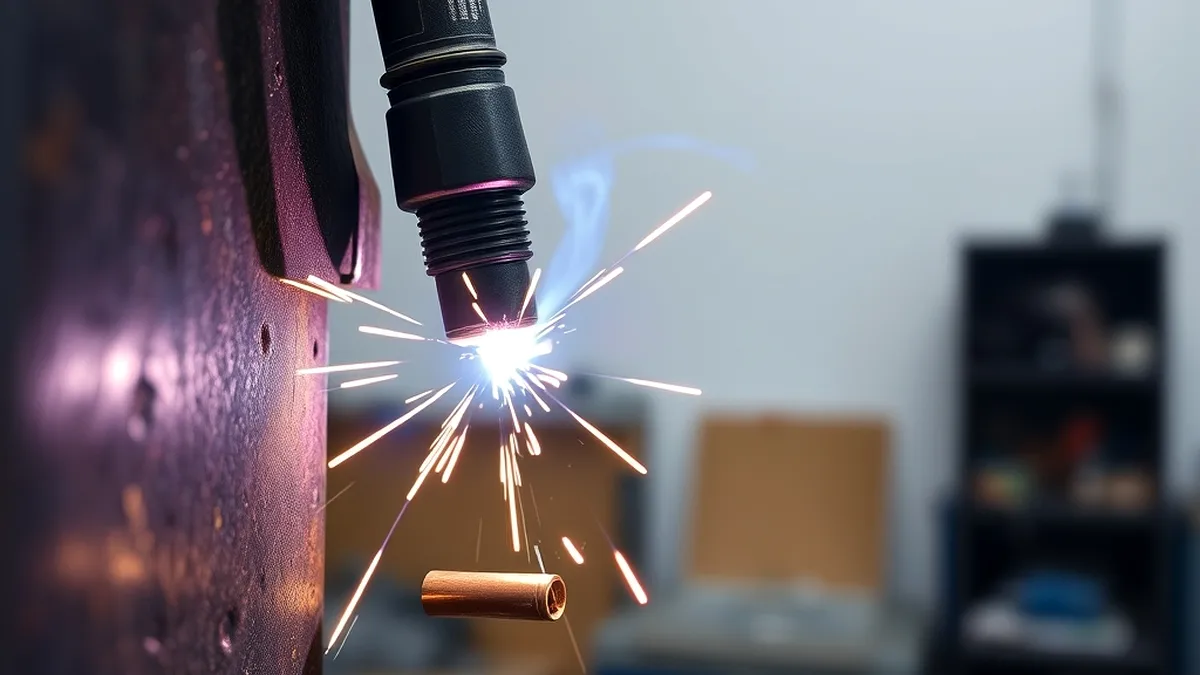
Yes, copper can be welded with flux-cored wire, and people do it successfully on radiators, bus bars, art pieces, roofing details and decorative work. But the phrase “can be welded” is doing a lot of heavy lifting in that sentence. It means the process is physically capable of producing a fusion weld in copper when the right filler, the right settings and the right preparation are in place. It does not mean it is the fastest route, the cheapest route, or the route an inspector would pick for a pressure line. Understanding the gap between possible and sensible is what separates a welder who gets paid from a welder who grinds out a ruined bead.
What “Possible” Really Means on Copper
Possible means three conditions are met at the same time. First, the filler metal deposited by the wire must be metallurgically compatible with the base copper, which usually means a bronze or silicon-bronze filler rather than a plain steel wire. Second, the machine must be able to deliver enough current density to establish and hold an arc while the base metal is stealing heat away, which pushes you toward higher-amperage units and short stick-out. Third, the joint has to be prepared to a standard that steel tolerates and copper does not, because copper holds onto oxide, oil and moisture and puts all of it straight into the puddle. Miss any one of those three and you will get a bead that looks acceptable and fails a bend test, or a bead that never ties in at all.
Where Flux Core Works Well on Copper
The sweet spot for flux core on copper is thicker stock, somewhere around 2 millimeters and up, welded in flat or horizontal position, where the process can lay down a heavy, fast bead and the extra heat input is an asset rather than a liability. Gutter and downspout repair, heavy copper bus bar, cast copper fittings and bronze-to-steel transitions all fall into this zone. Outdoors, flux core is often the only fusion process available without dragging a gas bottle across a yard. On jobs where appearance is secondary to strength and speed, flux core holds its own.
Where It Falls Short
Thin copper sheet under about 1.5 millimeters is where flux core starts losing arguments. The heat that makes the process productive on thick stock will blow through thin stock before you can reposition the gun. Precision assemblies, food-grade or refrigeration plumbing, anything requiring X-ray-quality roots, and cosmetic work where a clean bead profile matters all point toward TIG, brazing or soldering. If your project is a copper still that has to hold pressure, a refrigeration line that will run for a decade, or an art piece somebody will photograph, read the section on when to put the flux-core spool down before you commit. For general process comparisons, our MIG, TIG and stick breakdown covers the same decision matrix without copper in it.
Why Copper Punishes Bad Technique
Copper earns its reputation not because it melts badly, but because it makes every small mistake in your technique ten times more visible. Heat travels, oxygen attacks, and the metal moves. If you want to know why your first attempts looked like a caterpillar drowning in a puddle, the three properties below explain most of it.
Thermal Conductivity: The Number That Changes Everything
Pure copper conducts heat at roughly 400 watts per meter-kelvin. Carbon steel sits near 50. That is not a small difference, it is a different physical world. When you strike an arc on steel, the heat stays roughly where you put it long enough to melt a puddle. When you strike an arc on copper, the surrounding metal acts like a heat sink bolted directly to your weld zone, pulling energy away in every direction at once. The visible symptom is a puddle that will not stay open: you get a frozen lump with no tie-in at the toes, or you crank the heat to compensate and suddenly the puddle goes from frozen to runaway in half a second. There is a narrow window on copper, and it moves as the part heats up, which is why welders who do this work well are always thinking one bead ahead about where the heat is going.
The practical consequences are immediate. You need higher starting settings than the thickness would suggest on steel. You need shorter stick-out to keep the current path tight. You need to weld in segments rather than one long stringer, and you need to let the part cool between segments. A chunk of copper clamped to a steel table will pull heat even faster, so fixture choice becomes a heat-management decision, not just a holding decision.
Low Melting Point and a Wide Plastic Range
Copper melts around 1085 degrees Celsius, and its alloys such as brass and bronze vary from the high 800s to over 1000. The trouble is not the melting point itself, it is the distance between “solid and stable” and “liquid and sagging,” which on copper is crossed quickly and with little warning. Steel gives you a visible orange glow that tells you the metal is getting soft. Copper does not glow the same way, especially under a shade 10 to 13 lens, so by the time you see trouble the metal is already moving. This is why preheating decisions and travel speed discipline matter so much: you are trying to keep the entire part below the temperature where it slumps while still getting one localized zone hot enough to fuse.
Oxidation, Fumes and Porosity
Copper oxide forms almost instantly above a few hundred degrees. Left unshielded, it contaminates the puddle and produces porosity, brittle inclusions and a bead that will not wet out. The flux in flux-core wire fights this, but it cannot fight it alone if the base metal was not clean to begin with. Oxide has to be removed mechanically before the arc ever strikes, because the arc will happily melt oxide into the weld instead of burning it off. On alloys containing zinc, such as brass, you get a second problem: zinc boils at about 907 degrees Celsius, below copper’s melting point, so zinc fume comes off the puddle violently and produces the classic white fume that causes metal fume fever. That is a health issue as much as a welding issue, and it is covered properly in the safety section along with references to NIOSH welding guidance.
Pro Tip: If you can see a brown or black film forming on the copper while you weld, your shielding is losing. Stop, let the part cool, wire-brush the zone back to bright metal, and check your stick-out and gun angle before restarting. Grinding over contaminated bead metal only hides the problem; it does not remove the oxide that is now locked inside the weld.
Choosing the Right Flux-Core Wire for Copper
The single biggest decision in this whole process is the spool you screw onto the machine. Weld a piece of copper with mild-steel flux-core wire and you are not welding copper, you are gluing two pieces of steel to a piece of copper and hoping. Filler selection on copper is metallurgy, not preference, and the wire manufacturers have already done the science if you know what to look for on the label.
Characteristics of a Genuine Copper-Compatible Wire
A wire that belongs on copper work has four properties. It melts at or slightly below the base metal so the filler flows before the parent metal loses its shape. It wets the copper surface rather than balling up, which usually means a silicon or aluminum deoxidizer is present in the alloy. It produces a deposit with tensile strength and ductility matched to the application, since a hard, brittle filler on a soft copper base just moves the failure to the joint edge. And it survives the arc without excessive fuming, which rules out zinc-heavy brass wires on anything you will breathe near.
Check the classification before you buy. In the United States, AWS A5.6 covers copper and copper-alloy bare welding electrodes, with classifications such as ERCuSi-A for silicon bronze and ERCuAl-A2 for aluminum bronze, and the full classification tables are published by the American Welding Society. A wire carrying an AWS classification has been tested for chemistry and mechanical properties; a bargain spool with no classification is a gamble. The same discipline applies across every consumable you buy, and the same logic appears in our welding rod number decoding guide if you want the shorthand for reading any classification at a glance.
The Three Bronzes You Will Actually Use
Most copper-alloy flux-core and gas-shielded wires fall into three families, and each solves a different problem.
| Wire Type |
AWS Class |
What It Does Well |
Typical Use on Copper Work |
| Silicon Bronze |
ERCuSi-A |
Flows beautifully, low fuming, strong bond to copper and brass |
Sheet copper, ornamental work, brazed-style joints, patching |
| Aluminum Bronze |
ERCuAl-A2 / A3 |
Hard, wear-resistant, handles dissimilar joints |
Copper to steel transitions, bushings, heavy buildup |
| Phosphor Bronze |
ERCuP variants |
Good fluidity, resists porosity, springy deposit |
Wear surfaces, copper alloy fabrication, marine fittings |
Silicon bronze is the everyday answer for most copper repairs. It runs cooler than aluminum bronze, it wets copper readily, and the fume generation is modest compared with zinc-bearing alloys. Aluminum bronze is the structural choice when you are joining copper to steel or building up a bearing surface, though it demands more heat and better shielding. Phosphor bronze shows up in specialized fabrication where porosity resistance matters more than raw strength.
What to Avoid
Avoid plain mild-steel flux-core wire on copper under all circumstances. Avoid bare MIG copper wire without gas shielding unless your shop has the shielding dialed in perfectly, because unshielded copper oxidizes faster than you can travel. Avoid brass filler on jobs where zinc fume is a concern unless the job genuinely requires brass and you have extraction in place. And avoid bargain spools with no AWS classification, no lot number and no chemistry data printed on the label. If the box does not tell you what is inside, the manufacturer is not confident you would be impressed by the answer.
Short Note: Keep the spool dry. Flux-core wire picks up moisture in humid shops, and damp flux produces erratic arcs and extra porosity. Store spools sealed in their plastic, off the concrete floor, and if a spool has sat out through a wet season, run a foot of it onto scrap before trusting it on a real joint. Our storage approach mirrors the practice described in rod drying methods, adapted for wire.
Gas, Flux and Polarity: Setting Up the Atmosphere
Flux-core wire comes in two flavors: self-shielded, which carries everything it needs inside the core, and gas-shielded, which requires an external bottle to finish the job. Both can weld copper, but they fail in different ways, and knowing which one is on your machine changes how you set up.
Self-Shielded Versus Gas-Shielded on Copper
Self-shielded flux-core wire is the outdoor workhorse. The flux generates a carbon-dioxide-rich blanket as it burns, so wind has a much smaller effect than it does on a MIG setup. The trade-off is more slag, more spatter and a messier bead profile, all of which you will be grinding and chipping on copper where appearance counts. Gas-shielded flux-core, sometimes called dual-shield when it uses both core flux and external gas, gives a cleaner arc and a nicer profile, but it adds a bottle, a flow meter and a hose to the setup, which usually disqualifies it for driveway and field work.
For copper specifically, gas-shielded setups often win because the extra shielding keeps the oxidizing copper puddle cleaner. A 75 to 80 percent argon balance with the remainder carbon dioxide is a common starting envelope for gas-shielded flux core, though copper-alloy specialists often run straight argon or argon-helium blends with TIG. The full reasoning behind gas mixtures and their effect on arc characteristics sits in our gas setting breakdown, and the same pressure and flow logic applies here.
Polarity: Which Side Goes Where
Almost all self-shielded flux-core wire runs electrode negative, DCEP is common on gas-shielded variants, and getting this backwards produces an arc that sounds angry, spatters violently and deposits a weld with no penetration. Check the data sheet that came with the spool, set the machine to match, and verify on scrap before touching the workpiece. If the arc will not stay lit, if the wire stubs and pops, or if the bead sits on top of the copper like a cold globs of solder, polarity is the first suspect after wire feed speed.
Reading the Bead to Judge Shielding
The copper itself tells you whether the atmosphere was right. A properly shielded silicon-bronze bead on copper comes out bright, straw-colored or lightly iridescent. A starved bead comes out gray, sooty or blackened, and the surface will look dull no matter how much you polish afterward because the oxide layer is chemically bonded into the deposit. Porosity shows up as pinholes along the crown or, worse, under the surface where a grinder cannot find it. When the color goes wrong, fix the shielding before you fix the technique, because no amount of torch discipline overcomes an atmosphere that lets oxygen into the puddle.
Important: Never increase gas flow as a cure-all. Above roughly 25 cubic feet per hour on a typical nozzle, turbulent flow starts pulling ambient air into the shield, which makes porosity worse, not better. Fix stick-out, nozzle cleanliness and draft first. Clean nozzles and correct flow are part of routine maintenance covered in flux-core troubleshooting.
Preparing Copper Before You Strike an Arc
Steel forgives sloppy preparation better than any other common metal. Copper punishes it. Every hour spent cleaning is worth three hours spent grinding out a porous bead, and the cleaning routine for copper is more specific than the wipe-down you might do before welding mild steel.
Removing the Oxide Layer
Fresh copper in a shop develops a thin oxide film within hours. Copper that has been outdoors develops a thick green patina that is essentially a different material. Both have to go. Start with a stainless wire brush dedicated to copper, because a brush that has touched steel will embed iron particles in the copper and create galvanic corrosion sites later. Work the joint zone back to bright, pink metal, extending at least an inch beyond where the heat will travel. For heavier oxide or patina, a flap disc on a die grinder or 80-grit aluminum-oxide sandpaper works, again on tools reserved for non-ferrous work.
Degreasing: The Step People Skip
Copper pipe and sheet frequently arrive coated in cutting oil, drawing compound or fingerprints heavy with skin oil. Wipe the joint area with acetone, isopropyl alcohol or a dedicated metal degreaser using a lint-free rag, and let it flash off completely before you clamp anything. Solvent residue trapped in a joint vaporizes under the arc and becomes porosity, and on copper it also feeds carbon into a puddle that already has enough chemistry problems. Wipe, let dry, then handle the cleaned area only with clean gloves. A clean surface touched with dirty fingers is a dirty surface.
Joint Fit-Up and Tacking
Copper’s conductivity makes fit-up more critical than on steel. Heat that escapes through an air gap between two poorly matched pieces never comes back to the puddle, so you end up cranking the heat, which warps the parts, which opens the gap further. Aim for a gap no larger than the wire diameter. On butt joints in sheet, a tight lap with a hair of clearance beats a wide open root. Tack both ends and the middle of any joint longer than about three inches, because copper expands roughly 50 percent more than steel per degree of temperature rise, and a joint that starts aligned will walk out of position as the heat builds. For a broader primer on joint preparation that carries over across processes, see beginner welding fundamentals.
When to Preheat
Preheat sounds counterintuitive on a metal that already conducts heat too well, but the goal is never to make the copper hot, it is to reduce the temperature difference between the weld zone and the rest of the part. A modest preheat of 150 to 200 degrees Celsius on thick copper sections evens out the heat sink effect, reduces the thermal shock that causes cracking in constrained joints, and lets you run lower arc settings without losing the puddle. Thin stock almost never needs preheat. Joints on heavy cast copper, dissimilar-metal joints, and any joint held in a rigid fixture usually do. Heat the part evenly with a propane or oxy-acetylene torch, watch the temperature with a contact pyrometer or temp-stick rather than guessing by color, and keep the preheat consistent around the whole joint instead of hot-spotting one corner.
Quick Note: Preheat also drives off moisture. If the copper has been stored in a damp location or came in from outside on a humid day, a gentle warm-up pass before welding prevents steam-driven porosity that no amount of shielding gas will fix.
Machine Settings: Voltage, Amperage and Wire Speed
Settings are where theory meets the puddle, and on copper the usual thickness charts actively mislead you. A chart written for steel tells you to run 18 volts and 250 inches per minute for 3-millimeter plate; do that on copper and the heat vanishes into the sheet before a puddle forms, or blows straight through the thin edge depending on where the arc sits. Copper needs its own starting envelope, built from three numbers that you adjust together rather than separately.
Starting Numbers That Actually Work
For 2 to 3 millimeter copper sheet with a silicon-bronze flux-core wire around 0.035 inch (0.9 millimeter), a workable starting point on a 160 to 180 amp machine is 21 to 23 volts with wire feed around 220 to 260 inches per minute and a stick-out of roughly 10 to 12 millimeters. For 4 to 6 millimeter stock, move to 23 to 25 volts with feed climbing toward 300 to 350 inches per minute. These are starting points, not commandments. Copper’s thickness, the joint configuration, whether the part is clamped to a heat-sinking table and how many passes you have already run all shift the ideal number, which is why every experienced copper welder treats settings as a conversation with the puddle instead of a value dialed in once.
| Copper Thickness |
Wire (approx.) |
Voltage |
Wire Feed |
Stick-Out |
| 1 to 1.5 mm (thin, flux core marginal) |
0.030 in |
17 to 19 V |
150 to 190 ipm |
8 to 10 mm |
| 2 to 3 mm (the practical sweet spot) |
0.035 in |
21 to 23 V |
220 to 260 ipm |
10 to 12 mm |
| 4 to 6 mm (heavy, consider preheat) |
0.035 to 0.045 in |
23 to 25 V |
300 to 350 ipm |
12 to 15 mm |
Dialing In by Observation, Not by Hope
Run three test beads on a scrap piece of the same alloy, thickness and temperature as the real job, using the manufacturer’s published starting values as a baseline, such as the Lincoln Electric parameter charts that ship with most wire spools. The first bead tells you if the arc starts cleanly. The second, laid after the scrap has warmed, tells you how the settings behave once heat builds, which is the condition your real joint will be in by pass two. The third tells you whether the puddle stays controllable at the end when everything is hot. Judge each bead on three things: the sound, a steady sizzle rather than a crackle or a quiet hum; the tie-in, where the toes wash into the base metal instead of sitting on top of it; and the slag, which should peel in long curls once the bead cools to a dull red. If the slag refuses to lift, the bead is cold or contaminated. If the bead comes out flat, gray and full of pinholes, the shielding or the cleanliness is wrong, not the amperage.
Heat Input: The Number You Really Control
Heat input equals voltage times current divided by travel speed, and on copper travel speed is your main throttle. Slow down and you put more energy into a linear inch of joint, which risks melt-through and warping. Speed up and you leave a cold lap with no fusion. The trick specific to copper is that the part is getting hotter with every inch you weld, so a constant travel speed produces a joint whose start and end behave differently. Experienced welders speed up slightly as the part warms or break the joint into short segments with cooling pauses. Managing that gradient is the core skill, and it is covered in more depth in our parameters guide.
Pro Tip: Write your settings on a piece of tape stuck to the machine when a test bead comes out right. Copper jobs repeat themselves, and three weeks later you will not remember that 22.5 volts and 240 ipm were the magic combination for that particular thickness.
Technique: Angle, Travel and Heat Control
Settings get the puddle started. Technique decides whether it stays where you put it. On copper, gun angle and travel discipline matter more than they do on steel because the margin between too much and too little heat is narrower and the metal moves without warning.
Push, Pull and the 15 to 20 Degree Rule
Flux-core wire generally prefers a drag, pull technique, with the gun angled back about 15 to 20 degrees from vertical, pointing along the direction of travel. Dragging shields the fresh puddle behind the arc with the flux and the slag it produces, which matters more on copper because the oxide forms so aggressively. Pushing is occasionally useful on flat, clean, thin copper where you want to see the puddle clearly and preheat the joint ahead of the arc, but on anything vertical or out-of-position, drag. The gun should stay close, contact tip around 10 to 12 millimeters off the work, because a long stick-out on copper raises electrical resistance in the wire, softens the arc and lets heat wander.
Stitch Welding and Backstepping
Continuous stringer beads on copper are a recipe for warping. Stitch welding lays short segments, roughly 25 to 40 millimeters long, with a pause between each to let heat bleed out, then jumps around the part so no single zone accumulates too much energy. Backstepping, welding each segment opposite to the direction you traveled overall, locks earlier beads in place and keeps distortion marching in one predictable direction instead of twisting the part. On a long copper seam, the sequence matters more than the settings. Plan the order of segments before you strike the arc, the same discipline that applies to any distortion-sensitive job, and our spatter control tips pair naturally with this heat-management routine since both come down to stability and consistency.
Backing Bars and Heat Sinks
Clamping the copper against a thick copper or aluminum backing bar behind the joint does two jobs: it absorbs excess heat so the root does not blow through, and it protects whatever is behind the weld from spatter and drop-through. A copper backing bar is a thermal short, which is exactly what you want on thin sheet. On heavier sections where you are chasing penetration instead of avoiding it, a ceramic backing or a slight gap keeps the bar from stealing the root heat. Graphite blocks, water-cooled fixtures and even a wet rag under the clamp zone all play the same game. Anything that pulls heat away from the joint edge while you work is your friend, as long as it does not trap moisture against the weld.
Out-of-Position Work
Vertical and overhead copper welds are where flux core earns respect. Vertical-up on a copper fillet runs with settings dropped about 10 percent from flat and a tighter stick-out, letting gravity fight the fluid puddle less. Vertical-down is faster and usually wrong on copper except for the thinnest cosmetic runs where penetration is not the goal. Overhead copper work should start with the part repositioned if there is any option at all; molten copper is heavier and runnier than molten steel, and it does not forgive a slow hand. The vertical-up settings reference and the push versus pull breakdown both translate directly once you account for copper’s faster heat travel.
Quick Note: Rest the gun hand against a solid surface whenever possible. Copper punishes a shaky hand harder than steel does because the puddle is less forgiving and the travel speed has less room to vary. A simple fixture, a stack of blocks or your own wrist braced on the table all beat free-handing a precision seam.
Joint Designs That Work on Copper
Joint design on copper is about heat management as much as strength. Every geometry has a different relationship with conductivity, and choosing the wrong one means fighting the puddle for the whole job.
Butt, Lap and Fillet Joints
Lap joints are the most forgiving copper geometry for flux core because the overlapped sheets back each other up, the heat has somewhere to go, and the fillet can be sized gradually with multiple passes. Butt joints demand tight fit-up and often a backing bar, since the root has nothing to support it and copper will drop through before you have tied the sides together. Fillet joints on T-connections work well but need even heat on both members, or the thinner side melts away while the thicker side stays cold. The fix is an asymmetric torch angle that favors the heavy member, pointing the arc toward the thicker plate for a beat longer on each pass.
Bevels and Multi-Pass Builds
Anything over about 6 millimeters of copper benefits from a bevel, typically a 45-degree V on each side for a 90-degree included angle, ground clean of oxide before assembly. A bevel turns one impossibly hot pass into several manageable ones, each of which can be run cooler and cleaner. Cap passes on a beveled joint should be slightly wider than the root, tying the whole joint into a smooth profile that spreads heat over more area. Interpass temperature matters: keep the part under roughly 150 degrees Celsius before adding another pass, or you are welding into a preheated base that will run away from you.
Fixturing Against Movement
Copper’s higher thermal expansion rate means a joint that is clamped loosely at room temperature will be under real stress by the time it reaches welding temperature. Clamp firmly, use staggered tacks rather than one big one, and if possible weld in a sequence that balances heat across the joint, left side then right side, alternating rather than completing one edge entirely. Released fixtures should come off only after the part has cooled to near ambient, because taking a hot copper assembly out of a rigid fixture lets springback happen all at once, often with an audible ping and a misaligned part.
Preventing and Fixing the Usual Defects
Copper defects have a bad habit of hiding. A steel weld with a surface flaw usually announces itself; a copper weld can look decent while carrying a root full of gas. Knowing what each defect looks like, what causes it and how to respond saves whole afternoons.
Porosity: The Copper Plague
Pinholes in a copper weld come from one of four sources: contaminated base metal, moisture in the joint, insufficient shielding, or the wrong filler for the alloy. Start with the basics, re-clean the joint, check the nozzle and contact tip, verify polarity and confirm the stick-out is inside spec. If porosity persists, the wire itself may be the culprit, since flux-core wire that has absorbed moisture will inject gas into the puddle no matter what you do at the gun. Cut back to bare wire on scrap and see if the problem follows the spool. On brass or bronze with high zinc content, porosity may simply be zinc boiling out of the base metal, which means slower passes, better extraction and a filler that tolerates the fume.
Burn-Through and Melt-Through
The opposite failure is punching a hole through the root, which happens when settings are set for steel thickness rather than copper, when travel slows down at a tack or a corner, or when the part has no backing to absorb heat. The repair is immediate: stop, let the area cool completely, then fill the hole using a series of tiny spot tacks starting from the edges and working inward, never trying to fill it with one heavy pass. Prevention is a backing bar, correct voltage and a travel speed that stays constant. Our porosity deep dive covers the same diagnostic tree for every process.
Cracking and Lack of Fusion
Cracks in copper welds usually trace back to restraint, meaning the fixture held the joint so tightly that shrinkage stress had nowhere to go, or to filler mismatch, where a hard deposit on a soft base creates a stress concentration at the toe. Reheat treatment is rarely practical on repair work, so the answer is selection and sequence: a ductile silicon-bronze filler, balanced tacking, and a weld sequence that finishes on the least restrained side. Lack of fusion shows up as a bead sitting proud of the base metal with a cold, un-washed toe line. It means the heat was too low, the travel too fast or the angle too far off, and the fix is one more pass at slightly higher voltage with slower travel, overlapped 50 percent on the previous bead.
Undercut and Excessive Dilution
Undercut along a copper joint toe comes from too much voltage for the travel speed, which carves a groove faster than the filler can fill it. Drop the voltage, slow slightly, and let the puddle wash back into the groove. Dilution, where too much base metal mixes into the deposit and drags its properties down, is a subtler problem that appears when welding copper alloys with a dissimilar filler. Multiple passes fix it: the first pass is diluted, the second pass sits on a layer of your own deposit and reaches its intended chemistry.
Important: Never grind a suspect copper weld smooth and call it finished. Grinding hides porosity and lack of fusion while making visual inspection impossible. If the bead looks wrong, cut it out, clean back to sound metal and re-weld. The inspection section below explains what “sound” actually means.
Post-Weld Work: Cleaning, Inspection and Finishing
The job is not done when the arc stops. Copper work is judged by eye more often than by any other measure, and the difference between a professional result and a hobbyist result is almost always what happened after the welding stopped.
Slag Removal Without Damaging the Bead
Let the bead cool until the slag darkens and cracks, then lift it with a chipping hammer or a flat scraper held at a shallow angle. On silicon-bronze beads the slag usually pops off in curls if the settings were right. Follow up with a stainless wire brush, again the dedicated one, to clear the glassy film the hammer leaves behind. Never take slag off with a grinding disc unless you intend to remove weld metal too, and never leave slag trapped under a second pass, because the inclusion will sit inside the finished joint as a permanent defect.
Visual Inspection: What to Look For
Good copper welds are visually distinctive. The bead should be evenly rippled, roughly the width predicted by the settings, with toes that wash smoothly into the base metal instead of stepping down sharply. The color should be consistent along the length; a patch that went gray or black mid-bead marks the spot where shielding lapsed or the gun angle shifted. Look for crater cracks at every stop, pinch marks where the wire stubbed, and any pinhole along the crown. Tapping the joint with a light hammer produces a clear ring on a sound weld and a dull thud where a lack-of-fusion pocket sits under the surface. For structural or pressure work, escalate to dye penetrant testing, which will reveal surface-breaking defects invisible under a layer of polish, or ultrasonic testing for subsurface flaws. Destructive testing, cutting a sample coupon from the same setup and bending it in a vee-die, remains the fastest honest answer about whether your parameters produce sound metal.
Polishing and Restoring the Finish
Copper’s appeal is largely visual, so finishing matters. After slag removal, work through the grits, 120 to clean up the profile, then 220 and 400 for smoothness, and finish with a Scotch-Brite wheel or a polishing compound for that mirror glow. If the heat-affected zone has gone brown or rainbow-colored, that is surface oxide, not damage; it comes off with a light pass of dilute citric acid or dedicated copper cleaner followed by a thorough rinse and dry. Grind only enough to blend the bead into the surrounding surface, because every pass of the disc removes base metal and changes the section thickness you were trying to maintain.
Pro Tip: Wipe finished copper with a cloth and a little isopropyl alcohol before handing it over. Freshly polished copper picks up fingerprints within minutes, and the oils begin oxidizing immediately, leaving the piece blotchy on the customer’s table the same afternoon it left your bench.
When Flux Core Is the Wrong Tool
Knowing when to abandon a process is a higher-level skill than knowing how to run it. Copper has several joining routes that beat flux core outright for particular jobs, and using the wrong one stubbornly costs money and reputation.
TIG for Critical and Thin Copper
Tungsten inert gas welding is the reference standard for copper. Precise foot-pedal heat control lets you hold a puddle on 1-millimeter sheet without blowing through, straight argon or argon-helium shielding keeps the oxide off, and the bead quality approaches what aerospace inspectors demand. Helium additions matter more on copper than on almost any other metal because helium’s higher arc temperature compensates for copper’s heat sink effect, allowing faster travel and deeper penetration. If the joint is thin, cosmetic, pressure-bearing, food-contact or going into an inspection regime, TIG wins and the debate is over. The trade-offs against wire processes are covered in our MIG versus TIG comparison.
Brazing and Soldering When Fusion Is Not Required
Many copper jobs people try to weld do not need fusion at all. Plumbing joints, electrical lugs, decorative assemblies and thin-walled tubing are traditionally joined with brazing at around 600 to 800 degrees Celsius or soldering below 300, both of which put far less heat into the part, avoid melting the base metal entirely and produce joints that seal beautifully. Brazing with a silicon-bronze filler gives a joint strong enough for many fabrication tasks while keeping distortion near zero. If the base copper does not need to melt, fusion welding is usually overkill and always more destructive to the surrounding material. The distinctions between these processes are laid out in welding versus soldering and the related soldering versus welding guide.
A Simple Decision Table
| Job |
Best Route |
Why |
| Thin copper sheet under 1.5 mm, cosmetic |
TIG or solder |
Heat control and finish quality |
| Outdoor repair, thick stock, drafty conditions |
Self-shielded flux core |
No gas bottle, high deposition, portable |
| Copper to steel transition, structural |
Flux core or MIG with aluminum bronze filler |
Bridges dissimilar metals with controlled chemistry |
| Plumbing or pressure line |
Brazing or TIG |
Inspection-friendly, predictable strength |
| Ornamental piece, tight budget, home shop |
Flux core with silicon bronze |
Affordable, forgiving, good enough finish |
| Repair of a cracked cast copper fitting |
Preheat, TIG or carefully controlled flux core |
Cast structure needs slow, even heat |
Safety: Fumes, Light and the Stuff Nobody Watches
Every welding process has a hazard profile, and copper adds a couple of entries that steel work does not. Fume generation scales with heat input, and since copper work often means running hotter than steel work, extraction matters more here, not less.
What Comes Off the Arc
Burning copper-coated steel wire releases iron oxide plus the thin copper coating, and welding brass or bronze releases zinc oxide, the white fume behind metal fume fever, with its headache, nausea and chills. Flux-core processes add the flux’s own reaction products to the mix, which is why the process carries specific fume classifications. Standing in the plume for an afternoon is a bad idea under any circumstances. Set up cross-ventilation, use a fume extractor arm positioned close to the arc, and wear a half-face respirator with P100 particulate cartridges for anything beyond quick tacks in open air. Formal requirements for ventilation, respiratory protection and safe practices are set out in OSHA’s welding standards, with technical guidance in 29 CFR 1910.252. Fire control around hot work and sparking operations follows NFPA guidance, which matters on copper jobs because the flux slag and grinding sparks land in places people forget to sweep.
PPE for Copper Work
The baseline kit does not change from other processes, but the discipline does. An auto-darkening helmet in the shade 10 to 13 range handles the arc intensity while still letting you see the copper color between passes, which is exactly the information you need. A heavy leather jacket or a flame-resistant welding shirt keeps the heavier spatter flux core produces off your arms, gauntlet gloves protect the wrists where copper spatter likes to land, and steel-toe leather boots with metatarsal protection handle the hot offcuts that drop constantly when you are stitching around a large assembly. Safety glasses stay on under the helmet, always, because you will lift the hood a hundred times a day and the grinder is always within reach. Our general welding safety list is the checklist worth posting on the shop wall.
Eye and Skin Exposure
The arc produces ultraviolet and infrared radiation that burns corneas and skin the same way a sunburn does, and copper work done outdoors in reflective conditions doubles the exposure because the bright base metal bounces light into areas a shield would normally cover. Never strike an arc without your hood down, never let an uncovered observer catch the flash, and treat any red, gritty feeling in your eyes the day after a job as a real injury rather than something to sleep off. Even with a helmet, indirect glare around the edges of the lens causes eye strain over long sessions, which is why a good lens and a tight headgear fit pay for themselves. The details are covered in how welding affects your eyes and weld sunburn.
Quick Note: Copper turnings, dust and grinding swarf are a housekeeping issue with a health edge. Sweep them up as you go. Mixed with oils or flux residue, dry copper fines become another inhalable nuisance dust, and a slip on a pile of hot chips is how burn injuries happen.
Real-World Scenarios: Three Copper Jobs
Abstract advice sticks better when attached to a specific afternoon, so here are three copper jobs that show the decision process working from start to finish.
The Roof Valley Repair
A copper roof valley had split along an old seam about 150 millimeters long, and the homeowner wanted it fixed without lifting half the roof. The sheet was roughly 0.8 millimeters, far below flux core’s comfortable range, but the seam sat flat against timber with no way to get a backing bar underneath. The answer was not welding at all: the split was cleaned, flux applied and brazed with silicon bronze rod, then dressed flat. Two hours, no distortion, and a joint that will outlast the surrounding sheet. The lesson is that knowing flux core’s thin-sheet limits saved a job that fusion welding would have ruined.
The Dissimilar-Metal Bracket
A fabricator needed copper bus bar bolted to a steel mounting bracket with a permanent bond at the interface, on 5-millimeter material, outdoors on a plant rooftop. Gas bottles were impractical, the sections were thick, and the joint was structural. Self-shielded flux core with an aluminum-bronze wire handled it: preheat on the steel side to even the gradient, a beveled lap joint, stitch sequence working outward from the center, and a fume extractor positioned upwind. The bead came out gray-brown from the flux but ground clean and passed a dye penetrant check. This is the case where flux core genuinely beats everything else on the table.
The Sculptor’s Armature
An artist was building a large copper-skinned armature where dozens of short seams joined curved panels over a steel frame. Appearance mattered, the sheets were 1.5 millimeter, and the frame acted as a giant heat sink pulling energy from every joint. The shop tried flux core first and fought blow-through and warping for half a day. The fix was TIG for the visible skin panels and a handful of small flux-core tacks on the hidden frame attachments where speed mattered and nobody would ever look. Two processes, one project, each used where it belongs.
Practical Tips and the Mistakes That Cost the Most Time
Everything above compresses into a short list you can run in your head while standing at the machine. These are the habits that separate smooth copper jobs from long, grimy ones.
- Dedicate your brushes. A stainless brush that has touched steel will embed iron in copper and start galvanic corrosion. Keep a separate handle or mark it with tape.
- Clean wider than the joint. Oxide and oil migrate toward heat, so clean at least 25 millimeters past the weld zone on both sides.
- Test on scrap that matches the job. Same alloy, same thickness, same clamping, same temperature. A test bead on cold free-flat scrap tells you almost nothing about the real joint.
- Watch the color, not the clock. Bright straw means good shielding. Gray, sooty or black means something upstream failed and continuing will only make the repair bigger.
- Stitch and pause. Segments of 25 to 40 millimeters with cooling beats one long stringer every time on copper.
- Keep stick-out short. 10 to 12 millimeters keeps current density up and the arc focused where the heat sink is.
- Clamp against movement, not against heat. Rigid fixtures cause cracking; backing bars and heat sinks control temperature. Choose the right one for the problem.
- Manage the spool. Seal it, keep it dry, and treat a damp spool as a porosity generator waiting to happen.
- Know the exit ramp. If the settings climb and the puddle still will not behave, the job is telling you it wants TIG or brazing. Listen early.
Short Note: Flux-core parameters drift as the machine heats up over a long session. Re-check your bead after the first ten minutes of continuous running; voltage often climbs slightly once the transformer is warm, which on thin copper is the difference between a good bead and a hole.
The most expensive mistakes are the predictable ones. Welding with steel wire on copper, skipping degreasing, welding thin sheet with settings copied from a steel chart, grinding a porous bead smooth instead of cutting it out, welding a long seam in one continuous pass and wondering why the part banana-shaped, and ignoring the fume extraction because the job is “just a quick one.” Every one of those shows up in the troubleshooting habits catalogued at common flux-core mistakes.
Frequently Asked Questions
Can you successfully weld copper with a flux-core welder?
Yes, with the right filler wire, correct polarity, tight fit-up and disciplined heat control, flux-core welding produces sound joints in copper, especially on stock 2 millimeters and thicker, in flat or horizontal positions, with adequate ventilation. It is a legitimate technique rather than a gimmick, but it is not the universal answer: thin sheet, pressure joints and cosmetic work usually justify stepping up to TIG or brazing instead. Success depends far more on preparation and settings than on the brand of welder on your bench.
What type of welding is best for copper?
TIG is generally the best fusion process for copper because the foot pedal gives precise, continuous heat control and argon or argon-helium shielding keeps the puddle clean, which is critical on a metal that oxidizes rapidly. For non-structural joints, brazing with a silicon-bronze filler outperforms every fusion process on distortion and speed. Flux core earns its place for outdoor, thick-section and high-deposition work where portability and speed outrank finesse.
Is flux required when welding copper?
Flux is required in processes where nothing else shields the puddle, which includes stick brazing and some gas welding setups, and it is built into flux-core wire to do that job automatically. In TIG and MIG welding, an inert or active shielding gas replaces flux entirely, so no separate flux is needed. What is never optional is shielding of some kind, whether it comes from a flux coating, a flux core or a gas bottle. Unshielded copper oxidizes into a porous, brittle mess faster than you can finish a bead.
Are there special considerations when welding copper?
Four dominate everything else: copper’s very high thermal conductivity pulls heat out of the puddle faster than steel does, so settings and travel speed need compensating; it oxidizes instantly, so cleaning and shielding are non-negotiable; it expands more than steel per degree, so fixturing and weld sequence control distortion; and its alloys, particularly brass, can release zinc fume that is a health hazard requiring extraction and respiratory protection. Handle those four well and most of copper’s other quirks stay manageable.
What gas works best with flux-core wire on copper?
Self-shielded flux-core wire needs no external gas, which is its main advantage for field work. Gas-shielded flux-core variants typically run argon with 15 to 25 percent carbon dioxide, while pure argon or argon-helium blends are preferred when the same machine is switched to a copper-capable MIG or TIG setup. Flow rate should sit around 20 to 25 cubic feet per hour for a standard nozzle, adjusted upward only if drafting is severe, since excessive flow pulls air into the shield.
Do I need to preheat copper before flux-core welding?
Thin copper generally does not need preheat and can suffer from it if the whole part warms up and starts moving. Thick sections, constrained joints, cast copper and dissimilar-metal assemblies benefit from a modest 150 to 200 degree Celsius preheat, which reduces the temperature gradient, lowers the required arc settings and helps prevent cracking. The test is simple: if the part is heavy enough to pull heat away faster than your arc can supply it, preheat it.
Conclusion
Flux-core welding copper is not a trick question with a yes or no answer, it is a set of conditions. With a bronze-classified wire, tight preparation, settings built for copper’s conductivity rather than copied from a steel chart, short stick-out, stitch technique and proper extraction for the fumes, flux core joins copper quickly, outdoors, and with equipment a home shop already owns. Just as importantly, you now know the boundaries: thin sheet wants TIG, plumbing wants brazing, and pressure work wants both an inspector and the best process available. Dale, by the way, got his still running that Saturday, not with the flux-core spool but with a borrowed TIG torch after we talked through why the thin copper kept blowing through. He kept the flux-core machine for the heavy copper brackets he builds by the dozen, which is exactly where it belongs. Understand the process, respect the metal, and copper stops being the material that ruins weekends and becomes the one that pays for them.