Stick Welding Chart: The Complete Electrode, Amperage & Settings Reference (2026)
Stick welding chart guide: amperage by rod diameter, E6010 vs E7018, polarity, positions, and troubleshooting tables for SMAW…
READ ARTICLE →Last updated: October 2026
A few summers ago I watched a farm kid repair a cracked rotary-cutter blade spindle with a 5/32 rod on a 110-volt buzz box. The machine was maxed out, the rod was glowing cherry-red halfway to the stinger, and the arc sounded like a dying animal — sputtering, sticking, wandering. The weld he finally laid sat on top of the base metal like a caterpillar: tall, gray, and about as structurally useful as a chocolate teapot.
I handed him a 3/32, dropped the machine to 85 amps, and ten minutes later the same joint had a proper fused bead that’s still cutting hay three seasons later.
Nothing — not technique, not rod type, not machine quality — changes your results faster than rod diameter. It’s the setting that sets every other setting: choose the diameter and your amperage range is essentially chosen for you; choose the diameter and your penetration, deposition rate, travel speed, and defect risk follow. Get it right, and mediocre technique still produces serviceable welds. Get it wrong, and perfect technique can’t save you.
Yet rod size is the variable beginners guess at most often — grabbing whatever’s cheapest, whatever fits the stinger, or whatever’s closest in the box. This guide fixes that. You’ll get the complete arc welding rod size chart matching diameter to amperage to material thickness, the rules of thumb the pros actually use, the physics of why diameter controls everything, sizing guidance by rod type and material, machine-capacity realities (your 110V welder has opinions), troubleshooting for both too-big and too-small mistakes, and real project scenarios.
We’ll anchor it in AWS specifications, manufacturer data, and practical field experience — so the numbers on your screen survive contact with actual steel.
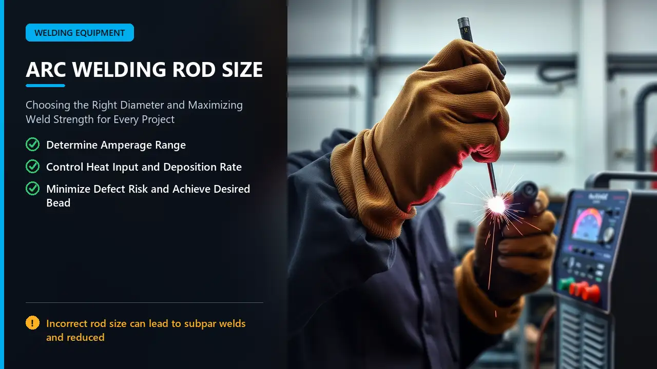
A stick electrode does three jobs simultaneously: it conducts the welding current, it becomes the filler metal, and its coating provides shielding and arc chemistry. Diameter governs all three.
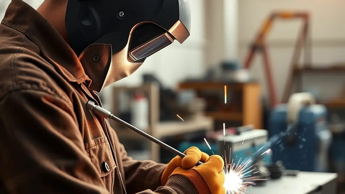
Electrical resistance in the rod generates heat; a thicker rod has more cross-sectional area and lower resistance per unit length, so it can carry — and needs — more current to melt properly. The practical relationship is remarkably consistent:
Approximately 1 amp per 0.001 inch of rod diameter is the classic rule. So:
– 3/32″ (0.094″) → roughly 60–95A
– 1/8″ (0.125″) → roughly 100–125A
– 5/32″ (0.156″) → roughly 140–175A
Below its amperage window, a rod won’t melt evenly — it sticks, stalls, and deposits cold metal. Above it, the arc becomes violent, the rod overheats (the steel core literally glows red up toward the holder), spatter explodes, and the base metal blows through. Amperage is not free choice; it’s dictated by diameter. Our what size welding rod should I use guide covers the same territory with project-specific examples.
Heat input is roughly amperage × voltage ÷ travel speed — and since amperage tracks diameter, rod size is the master dial on heat input. This is why:
Bigger rods melt more metal per minute (at their required amperage). A 5/32″ 7018 deposits substantially more weld metal per pass than a 3/32″, which is why structural shops run large rods in flat groove fills and small rods for out-of-position work. Deposition rate is the speed dimension of rod selection.
| Diameter | Typical Bead | Typical Defects When Mismatched |
|---|---|---|
| Small (< 1/8″) | Narrow, controlled | Lack of fusion on thick metal; rapid rod consumption; hard to bridge gaps |
| Medium (1/8″–5/32″) | Balanced | The general-purpose sweet spot |
| Large (> 5/32″) | Wide, high deposition | Spatter, undercut, distortion, blow-through on thin stock |
There’s a physical floor: the thinnest rod your machine can run reliably sets the thinnest material you can weld, and the thickest rod your machine can sustain sets your maximum productive thickness. Rod size is the bridge between your material and your machine.
In short: pick diameter first, and the rest of your setup falls into line.
Stick electrodes are manufactured in a standard range of diameters, expressed in inches (and metric equivalents):
| Diameter (in) | Metric (mm) | Common Name | Availability |
|---|---|---|---|
| 1/16″ | 1.6 mm | Sixteen | Light/precision work; limited rod types |
| 5/64″ | 2.0 mm | — | Thin sheet; some 6013s |
| 3/32″ | 2.4 mm | Three-thirty-seconds | Universal light-duty size |
| 7/64″ | 2.8 mm | — | Specialty; some 6010s |
| 1/8″ | 3.2 mm | Eighth-inch | The all-purpose workhorse |
| 5/32″ | 4.0 mm | Five-thirty-seconds | Medium plate, structural fills |
| 3/16″ | 4.8 mm | Three-sixteenths | Heavy plate, multi-pass |
| 7/32″ | 5.6 mm | — | Heavy fabrication (limited types) |
| 1/4″ | 6.4 mm | Quarter-inch | Heavy industrial |
| 5/16″ | 7.9 mm | Five-sixteenths | Very heavy; gouging/penetration work |
Availability reality: not every rod type comes in every size. The 7018 is common from 3/32″ to 1/4″; the 6011 from 3/32″ to 7/32″; the 6013 from 1/16″ to 5/32″. Specialty sizes (5/64″, 7/64″) appear in specific product lines aimed at sheet metal and pipe roots.
Electrodes also come in standard lengths — typically 14 inches for diameters up to 3/16″, with 18-inch lengths also common for medium sizes, and 12–14 inches for the heaviest diameters. Length matters practically: a longer rod gives more burn time per reload (efficiency), but a long, thin rod flexes and wobbles in your hand — which wrecks arc-length control. Out-of-position welders often prefer shorter rods for stability.
For the full landscape of rod formats and classifications, see welding rod types and uses and welding rod numbers explained.
Here’s the reference you’ll want printed and zip-tied to the machine. It combines diameter, amperage window, material thickness range, and typical applications.
| Rod Diameter | Metric | Amperage Range | Material Thickness | Typical Uses |
|---|---|---|---|---|
| 1/16″ | 1.6 mm | 20 – 45 A | 22 gauge – 1/16″ (0.5–1.5 mm) | Thin sheet, tacks, repair on light-gauge |
| 5/64″ | 2.0 mm | 30 – 60 A | 20 gauge – 1/8″ (0.8–3 mm) | Sheet metal, small parts |
| 3/32″ | 2.4 mm | 40 – 90 A | 16 gauge – 3/16″ (1.5–4.8 mm) | Light repair, thin plate, out-of-position finesse |
| 1/8″ | 3.2 mm | 75 – 130 A | 1/8″ – 1/4″ (3–6.4 mm) | General repair and fabrication — buy this size first |
| 5/32″ | 4.0 mm | 110 – 175 A | 1/4″ – 3/8″ (6–9.5 mm) | Medium plate, structural fillets, pipe fill |
| 3/16″ | 4.8 mm | 140 – 230 A | 3/8″ – 1/2″ (9.5–12.7 mm) | Heavy plate, multi-pass groove welds |
| 7/32″ | 5.6 mm | 170 – 260 A | 1/2″ – 3/4″ (12–19 mm) | Heavy fabrication (where available) |
| 1/4″ | 6.4 mm | 210 – 330 A | 3/4″ – 1-1/2″ (19–38 mm) | Heavy industrial, deep penetration passes |
| 5/16″ | 7.9 mm | 280 – 450 A | 1″ and above | Heavy cutting/penetration work, gouging |
Amperage ranges vary by electrode type — a 7018 runs its amperage differently than a 6011. Always defer to the carton’s data sheet. Ranges above reflect typical published windows from major manufacturers (Lincoln Electric, ESAB, Miller, Hobart).
| If your material is… | Use rod… | Set amps to… |
|---|---|---|
| Under 1/16″ (sheet) | 1/16″ or 3/32″ | 30–70 |
| 1/16″ – 3/16″ | 3/32″ | 55–90 |
| 3/16″ – 1/4″ | 1/8″ | 90–130 |
| 1/4″ – 3/8″ | 5/32″ | 120–175 |
| 3/8″ – 1/2″ | 3/16″ | 160–230 |
| Over 1/2″ | 1/4″ (multi-pass) | 220+ |
| Electrode | Go-To Size | Light Work | Heavy Work | Notes |
|---|---|---|---|---|
| 6013 | 1/8″ | 1/16″ – 3/32″ | 5/32″ (max, mostly light-medium) | Rod is limited to lighter gauges anyway |
| 6011 | 1/8″ | 3/32″ | 5/32″ – 3/16″ | Deep penetration — consider stepping down a size |
| 6010 | 1/8″ | 3/32″ (pipe root) | 5/32″ – 3/16″ | Root passes commonly 3/32″ |
| 7018 | 1/8″ | 3/32″ | 5/32″ – 1/4″ | Iron powder = high deposition at larger sizes |
The parallel chart for the gas-shielded world is our MIG wire size chart, and flux-core sizing lives in the flux-core amperage chart.
Charts are for the shop wall. These mental shortcuts are for the moment you’re standing in front of a job:
Rule 1 — The 1-amp-per-.001″ rule.
Amperage ≈ rod diameter in thousandths. 1/8″ → 125A; 5/32″ → 156A. Start there, adjust by puddle behavior.
Rule 2 — Match rod diameter to material thickness (roughly).
For mild steel, the rod diameter ≈ joint thickness works as a starting point for butt joints: 1/8″ rod for 1/8″ plate, 5/32″ for 5/32″ plate. Thin material: go smaller than the material. Thick material: go slightly smaller than full match and let multi-pass fill do the work — big rods on thick metal are for gross deposition, not precision.
Rule 3 — One size down for out-of-position.
Vertical and overhead welding use a rod one diameter smaller than you’d run flat, with amperage at the lower end of the range. The smaller puddle resists sagging.
Rule 4 — Thin metal: err small.
On any material under 1/8″, the safe bias is toward the smaller rod. You can always add a pass; you can’t un-blow a hole.
Rule 5 — When in doubt, 1/8″.
If you own one rod size for general mild-steel repair, own 1/8″. It handles the widest range of thicknesses on the widest range of machines.
Rule 6 — Check your machine’s ceiling before checking the chart.
A 110V machine producing 90A max makes the 5/32″ and 3/16″ rows theoretical. Your rod size list is bounded by your power source — see machine capacity below.
Rule 7 — Test on scrap of the same thickness.
Two beads on matching scrap tell you more than any chart. This is the habit every experienced welder relies on — formalized in our practice welding at home program.
The chart assumes a flat butt joint on clean mild steel in a neutral environment. Reality adds modifiers:
Two identical 1/4″ plates: one on a massive steel welding table, one hanging free. The table-clamped plate needs noticeably more amperage (or a step up in rod size) because the table drinks the heat. Fixtures, clamps, and backing bars all shift the effective setting. When you change your setup, retest.
| Position | Size Adjustment | Amps Adjustment |
|---|---|---|
| Flat | Base size | Base range |
| Horizontal | Base size | Base to slightly reduced |
| Vertical-up | One size down (recommended) | Lower end of range |
| Overhead | One size down | Lower end of range |
The physics: smaller rod = less deposited volume per second = the puddle solidifies before gravity wins. This is the same reason positional welding favors fast-freeze rods — see vertical welding techniques.
Two different goals:
Not all rods deposit metal at the same rate at the same diameter. Iron-powder electrodes (7018, 7014, 6013 variants) deposit significantly more metal per amp than plain cellulose rods — meaning a 5/32″ 7018 fills a groove faster than a 5/32″ 6011, and sometimes a smaller iron-powder rod matches a larger plain rod’s deposition. When comparing sizes across rod types, compare deposition, not just diameter.
Symptoms:
– Blow-through — the arc melts straight through thin plate before you can move.
– Excessive spatter — balls of molten metal peppering the workpiece and your surroundings.
– Warpage and distortion — heat overwhelms the material’s ability to sink it.
– Arc instability — the machine can’t sustain the amperage; the arc sputters and stalls.
– Washed-out, flat beads — wide, shallow, with potential undercut at the toes.
– Machine strain — on small welders: thermal overload shutdowns, breaker trips, melted stinger leads.
The structural consequence: distortion-induced residual stress, weak thin-metal joints, and — on heavier material — beads that look substantial but haven’t fused at the root. An oversized rod on thick metal with insufficient amperage is a classic “looks like a weld, fails like a seam” scenario. For why that matters quantitatively, see how strong is a weld.
Symptoms:
– Lack of fusion / cold lap — the bead sits on top of the plate, unfused at the toes.
– Insufficient penetration — no root fusion; X-ray or bend tests reveal it instantly.
– Rod overheats — the coating burns off early, the core wire glows red halfway to the holder, and you can’t finish a bead before the rod is consumed.
– Excessive consumption — you burn through rods at a alarming rate; economics of the job collapse.
– Exhausted machine duty cycle — running a small rod at its maximum continuously heats the machine.
– Fatigue and inconsistency — constant reloading breaks rhythm.
The structural consequence: a weld with a perfect appearance and a cold root — the most dangerous defect in welding because it’s invisible from outside.
| Your Symptom | Likely Size Problem | Immediate Fix |
|---|---|---|
| Blowing holes in thin metal | Rod too large | Step down one (or two) sizes; drop amps |
| Rod glowing red mid-bead | Rod too small (or amps too high) | Step up size; confirm amps suit rod |
| Bead sitting on surface, unfused | Rod too small (or amps too low) | Step up size; increase amps; improve technique |
| Constant sticking, weak arc | Rod too large for machine | Smaller rod; check machine capacity |
| Machine tripping breaker | Rod too large / amps too high | Smaller rod; lower amps; check electrical supply |
| Bead absurdly wide and flat | Rod too large | Step down size |
We break down each defect mechanism in porosity in welding and across our flux-core welding mistakes guide — the physics transfers across processes.
Each electrode’s personality interacts with diameter:
Sweet spot: 3/32″ and 1/8″. Available down to 1/16″ (genuine sheet work) and up to 5/32″ (light plate). Because the 6013’s arc is soft and penetration shallow, large diameters on heavy material produce wide, low-penetration beads — the rod’s chemistry caps its useful size for heavy work. The 6013 guide details its ideal range: 1/16″ for 22–24 gauge, 3/32″ for 16–20 gauge, 1/8″ for 1/8″–1/4″.
Sweet spot: 1/8″. Available 3/32″ to 7/32″. Because of its aggressive penetration, experienced welders frequently run a 6011 one size smaller than instinct suggests on moderately thick material — a 3/32″ 6011 at 85A welds 1/8″ plate beautifully with margin to spare. Full sizing in the 6011 guide.
Sweet spot: 3/32″ for roots, 1/8″–5/32″ for fills. The 6010’s very deep penetration means even small diameters dig hard — pipe root passes are classically run with 3/32″ 6010 precisely because its concentrated arc fuses the root without excessive heat.
Sweet spot: 1/8″ for general, 5/32″+ for groove fills. The iron-powder coating means a 5/32″ 7018 deposits like a larger plain rod — structural shops often fill with 5/32″ or 3/16″ in flat positions while using 1/8″ or 3/32″ for vertical and overhead. Storage rules apply regardless of size — see rod oven storage and the full 7018 guide.
| Rod Type | Typical Range | Size Note |
|---|---|---|
| 7014 (fast, smooth, non-low-H) | 3/32″ – 1/4″ | High deposition — often steps in for 7018 on non-critical fills |
| 7024 (flat-position production) | 1/8″ – 5/16″ | Iron powder heavy; flat-only; huge deposition at large sizes |
| 7010/7011 (70kpsi cellulose) | 3/32″ – 7/32″ | Pipe and heavy root work |
| Cast iron rods (nickel-based) | 3/32″ – 5/32″ | Small sizes preferred — heat control on crack-prone material |
Cast-iron sizing connects to our nickel-based welding wire and cast iron rod guide.
Everything in the master chart applies. This is the default material for stick sizing guidance.
Stick welding aluminum is rare (limited applications); TIG and MIG dominate. In TIG, the analogous sizing rule is tungsten and filler diameter — covered in our aluminum TIG settings chart. For MIG aluminum, see MIG aluminum with spool gun.
The zinc coating burns off violently — favor smaller rods and lower amperage to limit the fume burst and reduce the chance of trapping zinc in the puddle. Grind the coating back from the joint where practical. See welding galvanized steel with flux core for the process-agnostic principles.
The universal thin-metal doctrine: smallest rod the machine will run, amperage at the bottom of the range, fastest controlled travel, stitch-welding with cooling pauses. Our welding thin metal with an arc welder guide is the full playbook.
The chart is theoretical until you know what your machine can actually deliver — and that depends on your electrical supply as much as the welder.
Welder specifications list an output range (e.g., “120V: 25–140A” or “240V: 30–210A”). The maximum on paper isn’t always the maximum in practice — voltage drop from long extension cords, household circuits under load, and duty-cycle limits all shave off usable output.
Typical practical limits:
| Machine Class | Real-World Output | Largest Rod It Runs Well |
|---|---|---|
| 110V/120V entry inverter (120–140A rated) | 90–125A under typical home-circuit conditions | 1/8″ at upper range; 3/32″ comfortably |
| 110V multi-process (160–180A rated) | 110–140A | 1/8″; marginal 5/32″ |
| 220V/240V mid-range (180–200A) | 150–190A | 5/32″ comfortably; 3/16″ at limit |
| 220V heavy (230–250A+) | 200–240A | 3/16″–1/4″ |
| Engine-driven generator welders | Varies with power setting | Check generator output under welding load |
| Classic transformer buzz box (225A) | 40–225A AC | Full range — these machines are underrated for home shops |
The 110V reality: if your welder runs on a standard household circuit, you’re effectively limited to 3/32″ and 1/8″ rods for sustained work. Trying to force a 5/32″ 7018 through a 110V machine at 160 amps will trip breakers, overheat the machine, and produce an unstable arc. Work within your power class — or upgrade the machine, not just the rod.
Before running larger rods, verify your supply:
Select the largest rod your machine can run reliably at the top of that rod’s amperage range, then confirm it suits your material. A machine that can only manage 100A cannot run a 5/32″ rod properly even if the stinger physically holds it — and the arc will tell you so in the first three seconds.
Old transformer machines deserve special mention: a classic 225A AC buzz box will run a wider rod range than most modern 110V inverters — heavier, less efficient, but genuinely powerful. Our buzz box welding guide makes the case for keeping these machines alive.
Position deserves its own section because it’s the factor most often ignored when reading a thickness chart — and it’s where welders get into trouble.
Out of position = one size down, lower amperage, faster travel.
The reasoning: in vertical and overhead positions, gravity works against the puddle. A smaller rod deposits less molten metal per second, the puddle has less mass to sag, and the arc stays more controllable. The amperage reduction (typically 5–15 amps below your flat setting) further tightens the puddle.
| Position | Size | Amps | Technique Notes |
|---|---|---|---|
| Flat (1F/1G) | Full size | Full range | Base settings |
| Horizontal (2F/2G) | Full size | Slightly reduced | Tilt up 10–15° to fight gravity |
| Vertical-up (3F/3G) | One size down | Lower-mid range | Upward angle, weave/stringers per rod type |
| Vertical-down | One size down | Low end | Thin material; fast travel |
| Overhead (4F/4G) | One size down | Low end | Tight arc, fast travel, small puddle |
An overhead weld with a full-size rod produces a puddle with more mass than the arc’s surface tension can hold — it dribs, forming grapes of frozen metal (the classic “overhead drip” defect) and leaving a sagging, underfilled joint behind. The fix isn’t more skill; it’s less rod.
Fast-freeze rods (6010, 6011) hold position well even at larger sizes because their puddle solidifies quickly. Fluid-puddle rods (6013, 7018) are more position-sensitive — particularly overhead — making the one-size-down rule even more important for them.
Positional fundamentals for both rod choice and technique live in our vertical welding techniques guide, and horizontal-specific settings in horizontal flux-core welding settings (transferable concepts).
| Project | Material | Recommended Rod | Amps |
|---|---|---|---|
| Toolbox / steel box repair | 16–14 gauge sheet | 3/32″ 6013 | 50–80 |
| Gate or fence panel | 1/8″ tubing/angle | 1/8″ 6013 or 6011 | 85–115 |
| Lawn furniture frame | 1/16″–1/8″ tube | 3/32″ 6013 | 55–85 |
| Trailer light bracket | 14 gauge | 3/32″ 6011 | 60–85 |
| Shelving bracket | 1/8″–3/16″ | 1/8″ 6013/7018 | 90–125 |
| Handrail (non-code) | 1/4″ wall tube | 1/8″ 7018 | 100–135 |
| Axle/hitch repair (heavy) | 3/8″+ | 5/32″ 7018 | 140–175 |
Non-structural home repairs tolerate the general-purpose 6013; anything carrying human load or highway duty deserves proper rod selection and technique — when in doubt, consult a professional and follow applicable codes.
| Task | Typical Rod | Size |
|---|---|---|
| Fit-up tacks | 6011 or 6013 | 1/8″ |
| Fillet welds ≤ 1/4″ leg | 7018 | 1/8″ |
| Fillet welds 1/4″–1/2″ leg | 7018 | 5/32″ |
| Groove fill, flat | 7018 | 5/32″–3/16″ |
| Root pass (pipe) | 6010/6011 | 3/32″–1/8″ |
| Vertical-up groove fill | 7018 | 1/8″ (or 3/32″) |
| Capping | 7018 | 1/8″–5/32″ |
Exhaust tubing (16–18 gauge) punishes oversized rods — 3/32″ 6011 or 6013 at minimal amperage, with stitch technique, or better: MIG or flux core. Full technique in how to MIG weld exhaust pipe and flux core exhaust welds.
| Thickness | Approach |
|---|---|
| 1/2″ | 3/16″ rod, multi-pass, V-groove, possibly preheat |
| 3/4″–1″ | 3/16″–1/4″, multi-pass, interpass cleaning, preheat as needed |
| 1″+ | Procedure territory — qualified WPS, controlled preheat/interpass, larger rods in flat with 7018-type fills |
Base-plate work like welding rebar to plate and floor-jack pinch-weld repair scenarios demand the same thickness-first thinking.
Buying rods for learning: a 5-lb box of 3/32″ 6013 and a 5-lb box of 1/8″ 6011 covers the vast majority of beginner practice on 1/8″ plate — roughly $25–40 total for hundreds of beads. Add 1/8″ 7018 (in sealed bags) when you’re ready for structural technique. Our beginner welding tips and practice-at-home plan sequence the learning.
Stick electrodes carry markings — typically printed on the coating near one end:
Diameter is not in the AWS code. The classification describes the electrode’s metallurgy and geometry class, not its thickness — a common misconception (several online sources incorrectly claim the digits encode diameter; they don’t — the first two digits are tensile strength in thousands of psi). Diameter is printed on the carton, stamped on the rod end, or physically measured with calipers.
| Length | Typical Sizes | Why It Matters |
|---|---|---|
| 14″ | 1/16″ – 3/16″ | Standard shop length — good balance of burn time and control |
| 18″ | 1/8″ – 5/32″ | More burn time per reload — production efficiency; flexes more |
| 12″ – 14″ | 1/4″ – 5/16″ | Heavy rods are already stiff and heavy |
Practical take: longer rods mean fewer reloads (faster work) but worse handling control. Out-of-position welders commonly prefer 14″; flat-position production welders appreciate 18″.
Size selection means nothing if the rod is compromised before you strike the arc.
| Problem | Result |
|---|---|
| Moisture absorption | Porosity, hydrogen cracking (especially 7018) |
| Physical damage (dropped/cracked) | Arc instability, erratic bead, coating burn-off |
| Contamination (oil/grease) | Porosity, poor arc starts |
| Cross-storage of sizes | Wrong rod, wrong settings, wasted material |
| Defect | Possible Size Issue | Other Contributing Causes | Action |
|---|---|---|---|
| Blow-through | Rod too large | Amps too high; travel too slow; poor fit-up | Step down size; reduce amps; speed up |
| Cold lap / lack of fusion | Rod too small | Amps too low; travel too fast; dirty metal | Step up size; increase amps; clean joint |
| Excessive spatter | Rod too large for amps | Arc too long; wrong polarity | Verify size/amp match; shorten arc |
| Rod glowing red | Rod too small (overloaded) | Amps too high for rod | Step up size; recheck amps |
| Arc won’t hold / keeps sticking | Rod too large for machine | Cold machine; poor ground; damp rod | Smaller rod; check ground; fresh rod |
| Wide, flat, washed-out bead | Rod too large | Amps too high; travel too slow | Step down size; reduce amps |
| Tall, narrow, heaped bead | Rod too small (relative to amps) | Travel too slow | Step up size; verify amps; adjust speed |
| Undercut | Rod too large (excessive force) | Weave too wide; pause at toes; travel too fast | Smaller rod; narrow weave; steady motion |
| Distortion/warping | Rod too large (excess heat) | Fixturing; weld sequence | Smaller rod; stitch-weld; better fixtures |
| Porosity | Indirect (wrong rod type for material) | Moisture; contamination; wind | Correct rod type; clean; shield gas |
| Breaker trips | Rod too large for circuit | Extension cord; shared circuit | Smaller rod; dedicated circuit |
| Rod consuming too fast | Rod too small for deposition needs | High amps | Bigger rod; match deposition to task |
Consistent defect patterns are better diagnosed methodically — change one variable, weld a test bead. Our flux-core troubleshooting table follows the same logic for gasless processes.
When you face a new job, run this checklist — it takes about thirty seconds once it’s habit:
Step 1 — Measure the material thickness. Calipers or a gauge. Guessing starts the error chain.
Step 2 — Identify the base material and condition. Mild steel? Stainless? Cast iron? Rusty or clean? This narrows rod type first.
Step 3 — Confirm the rod type required by the application. Structural/code → 7018. Dirty/outdoor → 6011. Thin/cosmetic → 6013. (Full decision tree in our how to choose a welding rod guide.)
Step 4 — Pick the diameter from the master chart. Match thickness to row; adjust one size down for out-of-position work; adjust for heat sinking.
Step 5 — Check machine capacity. Can your power source deliver the top half of that rod’s amperage range? If not, step down a size or upgrade your electrical supply.
Step 6 — Set amperage. Use the rod’s data-sheet window; start mid-range; test.
Step 7 — Test on matching scrap. Two beads. Read the puddle. Adjust amps first, then reconsider size if the puddle still misbehaves.
Step 8 — Write it down. Thickness + rod + size + amps + polarity = your settings log entry. Build the log and you’ll never fully re-solve a job twice.
That process — measure, match, verify, test, record — is the entire discipline of rod sizing in eight steps.
Situation: A hobbyist welding 20-gauge sheet panels for a project cabinet tries a 1/8″ 6013 at 110 amps. Result: three blown holes, a warped panel, and shattered confidence.
Diagnosis: Rod oversized, amperage absurdly high for the gauge.
Fix: Switched to 3/32″ at 55 amps, stitch-welded with 1-inch segments and cooling pauses. Second panel: sound welds, negligible warp.
Lesson: The chart’s 1/8″ row starts at 1/8″ material — sheet metal lives in the 3/32″ and 1/16″ rows.
Situation: A repair welder joining 1/2″ plate ran a 1/8″ 7018 at 130 amps in a single pass. The bead looked acceptable but sat proud of the surface with cold toes.
Diagnosis: Rod too small and amperage too low for the thickness — insufficient heat for root fusion in a single pass.
Fix: Ground out the defective bead, ran 3/16″ at 190 amps with proper V-groove prep and two passes. Bend test coupon passed.
Lesson: On 1/2″ plate, 1/8″ rods are fill-pass tools, not single-pass solutions.
Situation: Repairing a manure spreader frame — 3/8″ angle iron, surface rust, generator-powered welder limited to 140A.
Constraint: The generator can’t sustain a 5/32″ rod at full range.
Solution: 1/8″ 6011 at 110–120A, beveled the joint, two passes with interpass cleaning. Deep penetration through the rust, full fusion despite the smaller rod.
Lesson: When machine capacity caps rod size, add passes and bevel prep — diameter limits are overcome by joint design.
Situation: A welder running 5/32″ 6013 overhead at 150 amps produced a string of frozen drips and an underfilled joint.
Diagnosis: Classic positional oversize — too much molten mass for surface tension overhead.
Fix: 3/32″ at 75 amps, tight arc, faster travel. Clean overhead bead.
Lesson: One size down isn’t a suggestion overhead — it’s physics.
Situation: A new welder with a 140A 110V machine asked what to buy. The store pushed a 50-lb case of 5/32″ 7018.
Better answer: 5 lb of 3/32″ 6013, 5 lb of 1/8″ 6011, and a 1-lb sealed pack of 1/8″ 7018 — all within the machine’s real output, covering practice, dirty-metal repair, and introduction to structural technique. Total: under $50, zero waste.
Lesson: Match the rod purchase to the machine and the projects, not to bulk-discount pricing.
Rod sizing isn’t just a quality decision — it’s an economic one, and the costs of getting it wrong show up in places beginners never think to look.
Every pound of rod you buy doesn’t end up in the weld. Stick electrodes lose material to:
– Spatter — molten droplets that land on the workpiece, floor, or your boots rather than in the puddle.
– Slag — the flux coating becomes waste glass, not weld metal.
– Stub loss — the inch or so of rod you can’t strike an arc with.
– Overweld — depositing more metal than the joint specification requires.
Typical stick welding deposition efficiency — the percentage of consumable that actually becomes weld metal — runs roughly:
– Plain-coated rods (6011, 6013): 45–55%
– Iron-powder rods (7018, 7014): 60–75%
– Overwelding with an oversized rod: efficiency drops further, because excess deposition must later be ground off (double cost: wasted rod and wasted labor).
Why size matters economically: a rod that’s too large forces you to run excessive deposition or rework blown welds; a rod that’s too small forces you to run more passes than necessary, each with interpass cleaning time. The right diameter minimizes both — fewer passes than an undersized rod, less waste than an oversized one.
A 50-lb case of budget 6013 at $2.50/lb looks cheaper than a 5-lb box of premium 7018 at $6/lb. But consider:
| Factor | Cheap Oversized Rod | Correct-Sized Quality Rod |
|---|---|---|
| Material cost per lb | Lower | Higher |
| Rods consumed per foot of weld | Higher (waste, overweld) | Lower |
| Rework probability | Higher | Lower |
| Grinding labor | More | Less |
| Pass count | Often more (poor control) | Optimized |
| Effective cost per sound weld | Higher | Lower |
Experienced fabricators buy specification-appropriate, correctly sized rod because the total cost of a weld — labor, rework, and consumables together — dwarfs the price of the electrode itself. A $10 rod mistake that costs an hour of grind-and-reweld labor dwarfs the rod price.
For planning (and for catching when something’s wrong), rough consumption estimates for mild-steel butt welds in flat position:
| Rod Size | Deposition Rate (approx.) | Consumes per Hour (continuous) |
|---|---|---|
| 3/32″ | 2–3 lb/hr | — |
| 1/8″ | 3–5 lb/hr | — |
| 5/32″ | 5–7 lb/hr | — |
| 3/16″ | 7–9 lb/hr | — |
Actual rates vary with rod type (iron-powder rods deposit faster), position, and technique — treat these as planning ballpark figures, not specifications.
If a job burns dramatically more rod than your estimates suggest, something’s off: usually oversize rods, excessive heat/speed problems, or overwelding. That’s your cue to revisit sizing.
The economics of consumable efficiency carry over directly to gas-shielded processes — compare flux-core wire speed and voltage and drive rolls for flux-core wire for the wire-fed equivalents of sizing discipline.
What influences arc welding rod size selection?
The dominant factor is base-metal thickness, followed by welding position, joint geometry, heat sinking, rod type, machine capacity, and penetration vs. deposition needs. The chart gives the baseline; the five modifiers adjust it.
How does rod size affect weld quality?
Diameter sets your amperage window, which sets heat input and penetration. Too large: burn-through, spatter, distortion, weak arcs. Too small: lack of fusion, cold lap, rod overheating, poor economics. Correct sizing is the foundation every other quality variable builds on.
Can the same rod size be used for all materials?
No — different materials have different thermal conductivity, melting behavior, and cracking sensitivity. Stainless wants smaller rods than mild steel at the same thickness; cast iron wants small rods and low heat always; thin aluminum (in TIG/MIG) follows its own charts. See MIG wire size chart for the gas-process equivalents.
What happens if I use the wrong size welding rod?
Possible results: insufficient penetration (hidden structural weakness), excessive spatter, blow-through, distortion, unstable arc, machine damage or breaker trips, and welds that fail inspection. The defects from wrong sizing are among the most common in both hobby and professional welding.
What size rod should a beginner start with?
3/32″ and 1/8″ — in a forgiving rod type like the 6013. Those two diameters cover nearly all practice scenarios on 1/8″ plate and light-gauge material, and both run comfortably on entry-level machines.
Is the 1 amp per .001 inch rule accurate?
It’s a reliable starting point for mild-steel butt joints, then the puddle tells you the final answer. It overestimates for thin material and ignores heat sinking, joint geometry, and rod type — use it to get near the dial position, not as gospel.
Does rod size appear in the AWS classification?
No. The AWS code (e.g., E7018) encodes electrode type, tensile strength, welding position, and coating — not diameter. Diameter is printed on the carton and stamped on the rod itself. (Many online articles get this wrong.)
What size rod for welding 1/4-inch steel?
Start with 5/32″ at roughly 130–160A for flat butt/fillet work; 1/8″ works for thinner sections of the 1/4″ range or when heat control matters. Test on matching scrap.
What size rod for overhead welding?
One size smaller than you’d use flat, at the lower end of the amperage range — commonly 3/32″ or 1/8″ for typical overhead work.
What size rod can my 110V welder run?
Most 110V machines handle 3/32″ and 1/8″ reliably; a few 160A+ units can pull a 5/32″ at reduced performance. Check your machine’s output rating and your circuit’s capacity — see what size breaker for a welder.
How do I choose between 14″ and 18″ rods?
14″ for control (out-of-position, precision work); 18″ for burn time (flat production welding). Handle both and prefer what your hand can steady.
Does rod size affect weld strength?
Indirectly and significantly: correct sizing ensures proper fusion and penetration, which are the mechanics of weld strength. A perfectly executed weld with the wrong-size rod’s lack of root fusion is weak regardless of appearance — explore the mechanics in how strong is a weld and is arc welding stronger than MIG.
Should I size rods differently for stainless steel?
Yes — typically one size smaller than mild steel for the same thickness, with 10–20% lower amperage, because stainless conducts heat less and melts more readily. See stainless steel stick electrodes.
How should welding rods be stored?
Cool, dry, sealed, in original packaging, off the floor, sorted by type and diameter, oldest stock used first. Low-hydrogen rods (7018) additionally require sealed bags and rod-oven discipline — see rod oven plans.
Does electrode length matter as much as diameter?
Less, but it affects handling. Long rods (18″) give more burn time per reload — efficient for flat production — but flex more and reduce arc-length control. Shorter 14″ rods are steadier for out-of-position and precision work. Diameter determines the weld; length determines your comfort.
Can I grind a rod to a smaller diameter?
No — the flux coating is precisely engineered for the core wire size, and grinding destroys the coating-to-wire ratio that governs arc behavior, shielding, and deposition. Buy the diameter you need.
What’s the most common rod-sizing mistake?
Using a 1/8″ rod for everything. It’s the right default for a huge share of work — but it’s wrong for thin sheet (use 3/32″ or 1/16″) and underpowered for heavy plate (use 5/32″+). The second most common: buying whatever diameter was cheapest in bulk without checking whether the machine and projects justify it.
Should I change rod size mid-project?
Yes, when the joint demands it — a common pattern is a small rod (3/32″) for the root pass on a gap or thin section, then a larger rod (5/32″) for flat fill passes, then a mid-size (1/8″) for the cap. Mixed-diameter procedures are normal in fabrication; just match amperage changes to each swap and test on scrap first.
Does rod diameter affect which machine I should buy?
Directly. If your projects are mostly thin sheet and light repair, a 110V machine paired with 3/32″ and 1/8″ rods is sufficient and cheapest to power. If you regularly weld plate over 1/4″, you need a 220V machine capable of 170A+ to run 5/32″ and 3/16″ rods properly — before buying either the machine or the rods, sketch out the thickest, most common material you actually work with, then size the machine, the circuit, and the rod inventory to that picture.
Are larger rods ever faster even on thin material?
No — on material under 1/8″, a larger rod’s extra deposition is consumed entirely by the heat problems it creates: burn-through, warpage, spatter cleanup, and rework. Speed on thin metal comes from correct small-rod technique and continuous travel, not from diameter. The productivity gains of larger rods only materialize on material thick enough to absorb their heat.
How do I know my rod size is right during the weld?
Listen and look. A correctly sized rod produces a steady crackle with a puddle that wets out smoothly just ahead of your travel, and the rod consumes at a comfortable pace without glowing. A rod that’s too small will feel sluggish — the puddle won’t spread, the rod will heat up in your hand. A rod that’s too large will feel violent — heavy spatter, a wide restless puddle, and base metal that softens faster than you can move. The arc tells you within seconds; the trick is learning to hear what it’s saying.
Rod diameter is the first decision and the most consequential one in arc welding. It locks in your amperage, shapes your heat input, sets your deposition rate, and determines whether your weld fuses into the metal or merely sits on top of it. Every other setting — polarity, travel speed, arc length, technique — is refinement on top of that foundation.
The rules to carry with you:
Buy rods in the sizes your machine actually runs and your projects actually demand — three well-chosen boxes beat a bargain case of the wrong diameter every time. Set the dial from the chart, strike the arc, watch the puddle, and let the diameter do its job.
The right rod, at the right size, is half the weld.