MIG Basics: The Complete Beginner’s Guide to MIG Welding (Setup, Settings & Technique)
Learn MIG basics from scratch: how GMAW works, machine setup, wire and gas choices, transfer modes, technique, troubleshooting…
READ ARTICLE →There is a special kind of frustration that comes from an arc going quiet in the middle of a good run. Last fall a friend of mine was welding handrails on a storefront job, moving along a 14-foot section of 1.5-inch square tube with the machine humming and the bead running nice, when the wire suddenly stopped feeding. Not gradually, not with a warning, it just quit. He pulled the trigger and heard a faint click, the arc sputtered out, and the next squeeze produced nothing at all. After fifteen minutes of checking the wall outlet, the gas bottle, and the settings panel, he was convinced the welder had died. Then a second-year apprentice opened the side panel, pointed at the drive assembly, and said the obvious thing nobody had said yet: the motor wasn’t turning when the trigger was pressed. In short, the wire feed motor is the small electric motor inside a MIG welder that pushes the welding wire off the spool, through the gun liner, and out to the arc at the speed you dial in, and when it stops, hesitates, or surges, the weld stops with it. The fix in this case turned out to be a blown control fuse and a seized drive roll from grinding dust, but the story illustrates something worth understanding: the wire feed motor is the heartbeat of a MIG machine, and most welders never think about it until it skips a beat.
That is a shame, because this component quietly decides a huge share of your results. The motor determines whether wire arrives at the puddle at a steady 250 inches per minute or a wandering 180 to 310 that makes the arc pop and stall. It decides whether your 0.030 wire feeds cleanly through a 15-foot gun or kinks and shreds against a worn liner. It governs how fast you can push deposition in a production environment, how well the machine tracks your dial settings from day one, and how much of your welding budget disappears into spatter cleanup and rework. Understanding what the motor does, what feeds it, what wears out, and how to diagnose it turns you from someone who waits for a service technician into someone who fixes the problem during the coffee break.
This guide covers the whole subject from the ground up: what a wire feed motor is and the exact job it performs, how the drive system around it works as a team, the different motor types from basic permanent magnet DC units to servo-controlled feeders, the components you can actually see and adjust, the factors that change how the motor behaves, tension and calibration techniques, a full troubleshooting routine for jams, surges, overheating, and dead motors, maintenance that doubles component life, upgrades worth doing and ones that are not, where the technology is heading, and three real shop stories that show why all of this matters. Whether you just bought your first 110-volt MIG welder or you run a production cell with an external feeder, the details below will change how you set up and care for your machine.
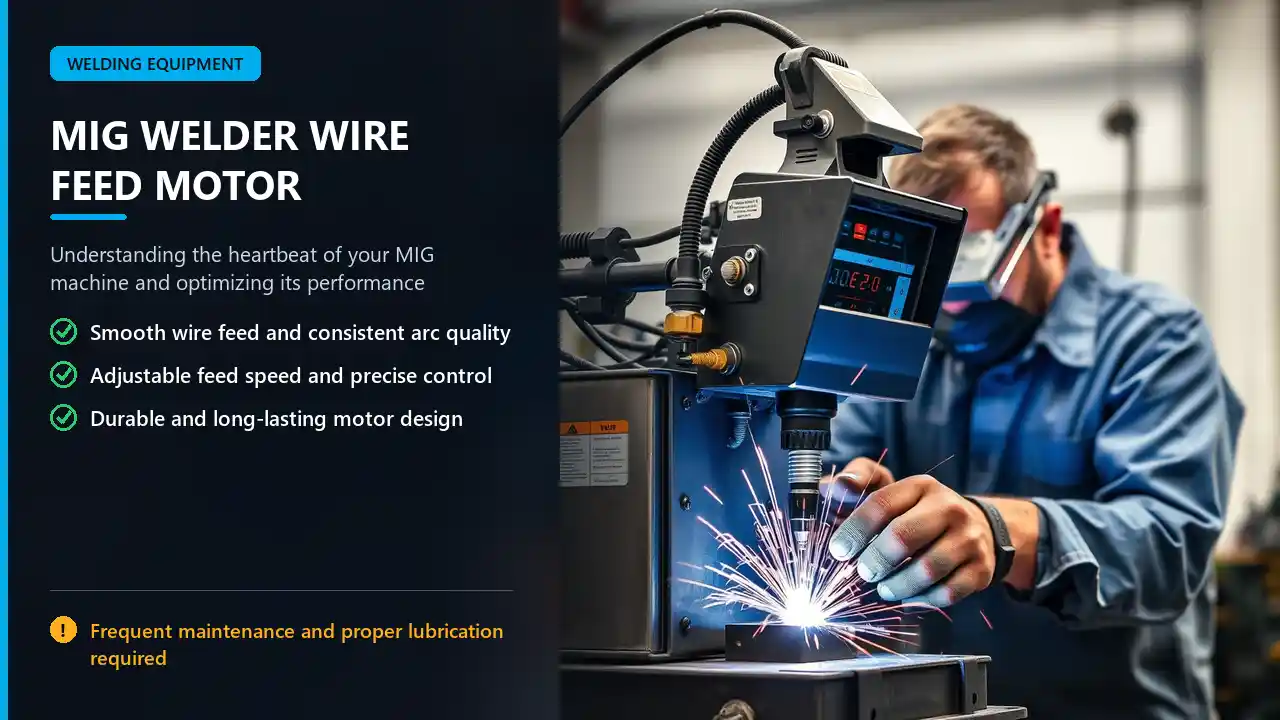
The wire feed motor converts electrical energy into precisely controlled mechanical motion. When you squeeze the trigger, power flows to the motor, it spins through a reduction gearbox, the drive rolls turn, and the rolls grip the wire and shove it forward at a rate measured in inches per minute. Everything that follows the motor in the chain, the liner, the gun, the contact tip, and the arc, depends on that motion being smooth, repeatable, and matched to what your settings demand. Nothing else in the machine has to be both strong enough to push wire through fifteen feet of curved liner and precise enough to hold a target speed within a few percent while the load changes at the arc.
If you want the simplest possible definition: the wire feed motor is what moves the wire. Not the welding current, not the gas, not the arc, the wire. It sits between your dial and the puddle, and it is the only component in the system that turns a number on a control panel into physical material placed in the joint. That is why experienced welders treat feed speed as the primary control on a MIG machine. On a constant-voltage power source, the machine responds to feed speed by adjusting current to melt whatever wire you send it, which means the motor’s output is effectively your amperage control in disguise. Set the motor slow and you get a cool, low-amperage arc for thin material. Set it fast and the machine ramps up to melt the extra wire, giving you hotter, deeper welds for thick stock.
This relationship deserves its own paragraph because it is the single most useful thing to know about wire feed systems. In a constant-voltage MIG setup there is no amperage knob. The power source holds your voltage setting steady and automatically produces whatever current is required to melt the incoming wire. Push wire faster and the machine works harder, driving current up. Slow the wire down and current drops. In practical terms, most operators find that each inch per minute of wire feed on mild steel corresponds roughly to one amp of welding current, though the exact ratio shifts with wire diameter, alloy, and shielding gas. Feeding 0.035 wire at 300 inches per minute puts you in the neighborhood of 250 to 300 amps, plenty for a heavy fillet on 3/8-inch plate. Feeding at 150 inches per minute lands near half that, appropriate for sheet.
The motor is therefore not a minor accessory, it is half the equation of every weld you make. A motor that cannot hold its commanded speed cannot hold your amperage either, and every downstream problem, cold lap, spatter, inconsistent penetration, follows from that instability. This is why the wire speed and voltage pair deserves careful attention, and our wire speed and voltage chart gives you starting points for the common thicknesses so you know what target the motor is supposed to hit.
On most compact MIG welders, the motor lives inside the front compartment next to the wire spool, mounted to a bracket with a gearbox output shaft pointing at the drive roll assembly. You can usually see it by opening the same panel where you load wire. On suitcase-style feeders and portable units used in construction, the motor sits in its own housing that clamps to a cart or sits on the ground near the weld area, connected to the power source by a cable and to the operator by the gun. Either way the arrangement is the same: motor, gearbox, drive rolls, tensioner, gun. Industrial machines may add a second set of rolls inside the feeder, and some run two motors in a push-pull arrangement where a motor in the feeder pushes and another in the gun pulls, which we will get into under upgrades.
Knowing where to find the motor matters for service. Panel-off inspections take two minutes and let you check for dust, listen for bearing noise, confirm the drive roll groove matches the wire, and verify that the tension knob is in a sane position. If you have never opened the panel on your machine, do it today with the machine unplugged. You will learn more about your welder from five minutes of looking than from an hour of reading. Newer owners may also want our walkthrough on using a MIG welder for the first time, which includes a tour of the machine’s working parts.
Quick Note: Unplug the machine before reaching into the wire feed compartment. The control circuit is low voltage, but the output terminals are not, and habits around hot equipment are what keep fingers and rings out of trouble.
No motor feeds wire alone. The drive assembly is a small mechanical system with four partners, and the quality of the whole depends on each one doing its job. Understanding the handoff from spool to arc explains why a perfectly good motor can still deliver terrible results when a five-dollar part upstream is worn.
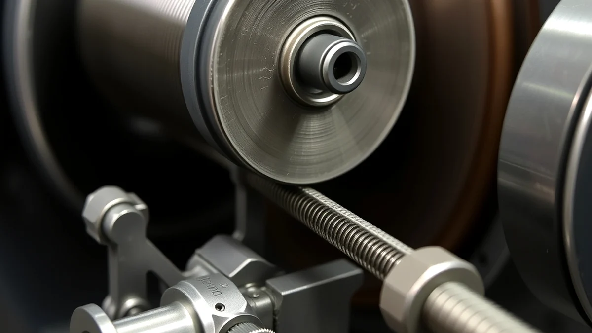
The path starts at the spool, which sits on a spindle with a brake or clutch that lets wire unwind without overrunning when the motor stops. From there the wire passes through a short inlet guide, into the drive roll nip where the powered rolls grip it, out through an outlet guide, and into the gun liner, a tightly wound steel or plastic tube running the length of the gun. At the end sits the contact tip, a small copper alloy nozzle with a bore that touches the wire and transfers welding current into it, followed by the gas nozzle that shapes the shielding gas envelope. Each transition point adds a little friction, and friction is the enemy of consistent feeding. Total drag grows with gun length, number of bends in the liner, and the condition of every surface the wire slides against.
A practical way to feel this is to disconnect the gun from the feeder and push wire through the liner by hand. On a clean 10-foot liner, it should glide with light pressure. On a damaged or contaminated liner, you will feel grinding, tight spots, or periodic catches, and the motor has to fight through all of it while trying to hold an exact speed. That fight shows up at the puddle as a wire feed that surges and stalls. If you want to understand the whole transport chain in more detail, our deep dive on mastering the wire feed welder covers technique alongside equipment.
The drive rolls do the actual pushing, and they come in groove profiles chosen for the wire. A V-groove roll suits hard, round solid wire because it grips cleanly without deforming it. A K-groove or U-shaped roll handles softer wires such as aluminum that a sharp V would flatten. A knurled roll has tiny teeth that bite into the soft outer surface of flux-core wire, which has a tubular construction that would otherwise crush under smooth pressure. The mating side of the pair is usually a smooth idler roll. Putting a knurled roll on solid wire, or a V-groove on flux core, is one of the classic setup errors: it either flattens the wire so it will not pass through the contact tip, or it slips and delivers wire in jerks.
The tensioner is the spring-loaded arm that squeezes the idler against the powered roll. It exists because friction alone will not hold wire reliably against the resistance of the liner, and because the amount of squeeze you need depends on the wire. Too little tension and the rolls spin while the wire stands still. Too much and the wire deforms, the motor works harder than it should, and you get shavings, flat spots, or a jammed liner. The tension knob is the most adjusted control on any MIG machine and the most often misadjusted, which is why we give it a dedicated section below. The liner itself is a consumable, particularly with flux-core wire, which carries abrasive flux particles through it, and a fresh liner is one of the cheapest performance upgrades available.
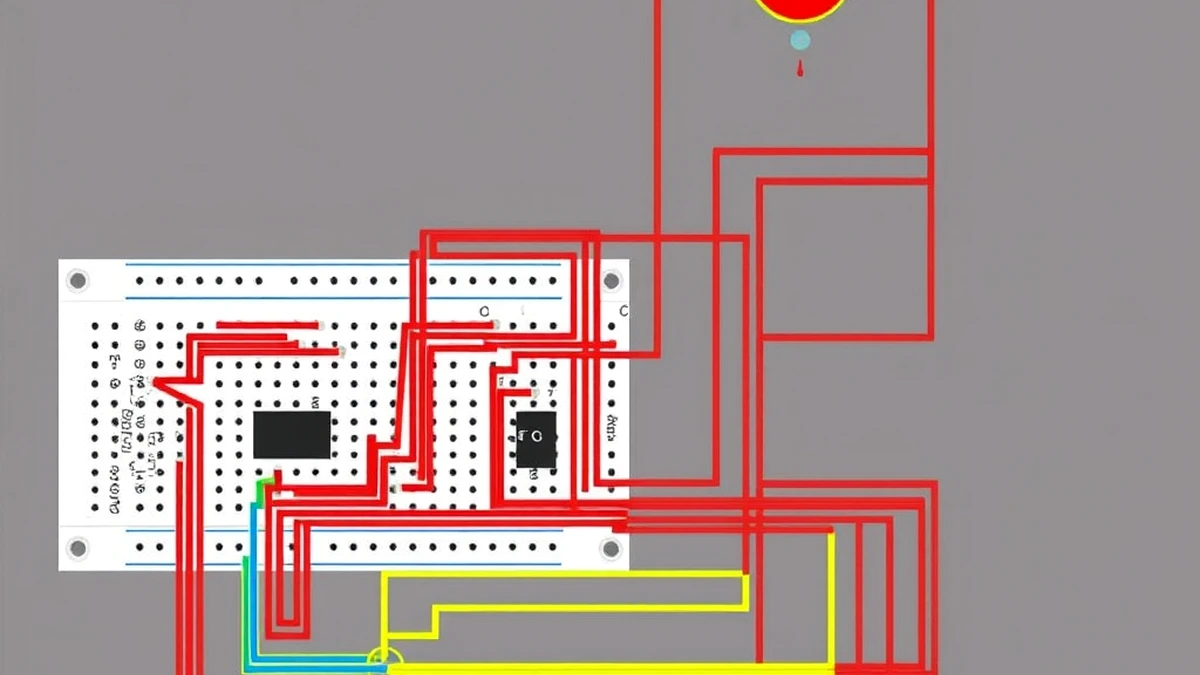
Between your finger and the motor sits a small control circuit that most welders never consider. The trigger switch sends a low-voltage signal to the machine’s control board, which then does three things: energizes the welding contactor so the output terminals go live, opens the gas solenoid so shielding gas starts flowing a fraction of a second before the arc does, and commands the wire feed motor to spin at the speed set on the panel. On simple machines this is a basic two-wire control. On more sophisticated units the machine may add a soft-start ramp so the wire does not lunge at the puddle, a burnback function that keeps the wire energized briefly after the trigger is released so it does not stick to the work, or a spot-timer function. Many modern inverters also drive the motor through a pulse-width modulation controller that varies power to the motor dozens of times per second, giving smoother speed control across the whole dial range than an old rheostat ever could.
When the motor does not run at all, the trigger circuit is usually where the fault lives, and the diagnostic logic is straightforward: does the gas flow when you pull the trigger? If gas flows but the motor does not, the fault is in the motor branch. If neither works, the trigger switch or control board is suspect. That decision tree is covered in the troubleshooting section further down.
Pro Tip: Listen to the first half second after every trigger pull. A healthy machine makes a soft, immediate whir as the motor spins up. A labored groan, a click with no motion, or a rush of speed followed by a drop all point at the feed system rather than the arc settings.
Not all feed motors are created equal, and the differences show up in smoothness, longevity, and how precisely the machine holds speed under load. The market spans from inexpensive brushed motors in entry-level units to encoder-equipped servo systems in production feeders.
| Motor Type | Where You Find It | Strengths | Trade-Offs |
|---|---|---|---|
| Permanent magnet DC (PMDC) | Most hobby and light-industrial MIG welders | Simple, inexpensive, strong low-speed torque, easy to replace | Brushes wear over time, speed can drift under varying load |
| Brushed DC with gear reduction | Mid-range machines and many external feeders | Good torque at low cost, forgiving, widely available parts | Brush maintenance, electrical noise at the brushes |
| Brushless DC (BLDC) | Premium machines and modern inverters | No brushes to wear, cooler running, longer service life, cleaner control | More complex driver electronics, costlier to repair |
| Servo motor with encoder | Production wire feeders and automated systems | Closed-loop speed accuracy, consistent under load, programmable ramping | Highest cost, needs a controller and feedback electronics |
The workhorse of the hobby world is a small permanent magnet DC motor, typically running on low control voltage and connected to a reduction gearbox that trades speed for torque. These motors deliver strong turning force at low speeds, which is exactly what you want when the rolls have to push wire through a long liner against friction. Their simplicity is their virtue: two brushes, a commutator, a magnet, and a gearbox. Their limitation is the brushes, which are carbon blocks pressed against the spinning commutator and which slowly wear into dust over hundreds of hours. Worn brushes cause intermittent contact, so the motor may hesitate, run at reduced speed, or stop until you tap the housing. Replacement is an inexpensive repair that any competent shop can do in under an hour.
At the higher end you find brushless motors, which replace the physical brushes with electronic commutation. Nothing rubs inside, so there is far less wear, the motor runs cooler, and the drive electronics can regulate speed with much tighter tolerances. Many machines marketed at professional fabrication shops use brushless feed motors precisely because they hold setting all day long, including at the low end of the dial where cheap motors tend to lurch.
Servo systems add an encoder, a device that reports the motor’s actual shaft position and speed back to the controller many times per second. The controller compares measured speed to commanded speed and corrects instantly when a bend in the liner or a heavier wire tries to slow the motor down. That closed-loop behavior is the difference between a feeder that sags when you push the gun into a corner and one that delivers identical wire speed regardless of what the load is doing. Production feeders, automation cells, and long-gun setups benefit enormously from closed-loop control, and it is one of the main reasons two feeders with similar specifications can feel completely different in the hand.
Every feed motor pairs with a gearbox, and the gear ratio sets the character of the drive. A high reduction ratio multiplies motor torque so the rolls can push stubborn loads, at the cost of top-end speed. A lower ratio lets the motor spin wire out fast but with less pushing force. Manufacturers choose the ratio to match the machine’s intended duty: a small 110-volt welder aimed at sheet metal and light brackets needs a different balance than a 250-amp unit expected to push 0.045 wire through a 15-foot gun. Gearboxes also introduce their own failure modes. Worn gears, stripped teeth from a jammed wire, or a loose output shaft all show up as noise, slipping, or a motor that spins while the rolls do not turn. Listening to your gearbox is genuinely useful diagnostic work: new machines whir quietly, and a change in pitch over time means something has changed inside.
Short Note: More expensive motors matter most at the extremes of the dial. At mid-range settings even a cheap motor feeds acceptably. At very low or very high speeds, quality separates quickly.
It is tempting to think of the feed system as plumbing, something that just moves material and has no say in the metallurgy. That is wrong. Because feed speed sets amperage on a constant-voltage machine, motor performance reaches directly into the weld’s mechanical properties.
Deposition rate, the amount of filler metal you place per minute, is a direct function of how fast and how steadily the wire arrives. A motor that holds 300 inches per minute without sagging lets you run the exact current your procedure calls for, pass after pass, hour after hour. A motor that wanders between 270 and 320 under the same setting delivers a weld that is nominally one size but actually a different size every few inches. In a shop that welds to a written procedure or a code, that variability is the difference between a pass and a reject. Even in casual work, inconsistent deposition makes beads look uneven and forces you to slow down to compensate, which costs productivity you never get back.
Underfeed starves the arc. When the wire slows below the setting, the machine cannot maintain the current it was set for, penetration drops, and the bead sits cold on the plate with wet, un-fused toes. Overfeed does the opposite: the machine ramps current to keep melting wire, the puddle goes wide and hot, and on thin material you punch through. Bead appearance tracks the same variable. Steady feed gives even ripples and consistent width; variable feed gives a bead that widens and narrows along its length like a dotted line. If your beads look uneven and your settings have not changed, look at the feed system before you blame your hand. Polarity plays its own role in this picture and is covered separately in our guide to MIG polarity explained, but polarity and feed speed work as a pair.
Short-circuit transfer is a rhythmic process. The wire touches the puddle, short-circuits, melts off, the arc re-establishes, and the cycle repeats dozens of times per second. That rhythm only stays locked if wire arrives at a constant rate. When the motor hiccups, the rhythm breaks, the arc stutters, and spatter jumps. Every experienced welder knows the sound of a surging feed system, a crackle that keeps tripping over itself no matter how carefully the gun is held. Before touching the voltage knob, check whether the feed is the culprit. Practical fixes for spatter problems beyond settings are collected in our article on reducing flux-core spatter, and the basics of whether the process itself suits your application are covered in whether MIG welding is strong.
Quick Note: Three symptoms that almost always trace back to the feed system rather than the arc: spatter that appears without a settings change, beads that wander in width, and a crackle that never sounds quite even.
Now the anatomy lesson. Four assemblies do the work, and each one has a failure signature worth memorizing.
The motor assembly is the motor itself, its gearbox, the mounting bracket, and the output shaft that drives the rolls. In quality machines the whole assembly is isolated on rubber mounts to damp vibration, because vibration transmitted through the frame can shake the drive rolls loose over time. The shaft is usually keyed or splined into the drive roll, and if that interface wears, the roll can spin on the shaft while the motor turns, which looks exactly like a motor fault but is a mechanical one. Signs of assembly trouble include a motor that runs but the rolls do not turn, a rhythmic knocking from the gearbox, heat at the housing beyond what a long duty cycle would explain, or intermittent stopping that correlates with the machine being bumped.
Drive rollers are hardened steel wheels with a machined groove sized to the wire, mounted on the motor shaft and on the tension arm. They are consumables with a long life, hundreds of pounds of wire if you keep the groove clean, but they do wear. The groove profile rounds over, the gripping edges soften, and eventually the roll starts slipping on wire it used to feed without complaint. Worn rolls leave shiny flat marks on the wire and produce fine metallic shavings that collect in the feed path. The single most valuable habit in feed system maintenance is swapping rolls when you change wire size anyway, because the groove must match the diameter to within thousandths of an inch. A 0.030 roll running 0.035 wire slips; a 0.035 roll running 0.030 wire can pinch and shave it. Groove selection for flux core and other specialty wires is covered in our dedicated piece on drive rolls for flux-core wire.
The tensioner is a hinged arm with an idler roll and a spring-loaded adjuster, usually a knob with a numbered scale or a wing nut. Its job is to press the idler against the drive roll with a consistent, adjustable force. Good tensioners have a smooth, linear feel so you can dial in small changes, and many include a quick-release lever so you can back the pressure off when threading new wire. Cheap tensioners develop slop at the pivot, which lets the arm flutter under load and produces exactly the intermittent feeding you were trying to avoid. When you buy or evaluate a machine, play with the tension arm. Smooth and firm is good; notchy, loose, or requiring a heroic squeeze to release is a warning sign about the rest of the assembly too.
Often overlooked, the spool holder matters more than people expect. The spindle carries a spring-loaded brake that resists the spool’s tendency to keep spinning when the motor stops, a phenomenon called overrun that can push a loop of wire into the drive rolls after every trigger release and eventually cause a nest. Adjust the brake so the spool stops promptly when feeding stops but still unwinds freely while welding. If the brake is too tight the motor strains and can overheat; too loose and you get slack wire piling in the compartment. When you install a new spool, give the spool a spin by hand and feel the drag. It should coast briefly and stop, the way a good reel behaves on a fishing rod. Keep spools clean and dry as well, because rusty wire drags in the liner and our notes on keeping MIG wire from rusting explain storage habits that preserve feedability.
Pro Tip: When you finish a spool, cut the wire cleanly and tuck the end into the spool’s retaining hole before removing it. Wire that springs loose mid-change is how nests and kinks start.
Even a perfect motor has to fight real-world variables. Five of them dominate, and knowing them lets you predict problems before they reach the puddle.
Diameter changes both the resistance the motor overcomes and the speed required for a given amperage. Thinner wire needs to run faster to deliver the same current, so the motor works at higher rpm, while thicker wire needs more pushing force per inch. Type matters as much as size: solid wire is smooth and dense and feeds predictably; flux-core wire is hollow and softer and wants a knurled roll to grip it; aluminum wire is soft enough to deform under the wrong roll profile and slick enough to slip. A wire that is undersized for your gun or oversized for your contact tip creates friction spikes the motor has to absorb continuously. Match wire to the machine’s rated range, and remember that a job welding 0.023 wire on sheet needs a very different feed setup than one welding 0.045 on structural plate. Our MIG wire size chart maps diameters to applications, and the common flux-core sizes are compared in 0.030 versus 0.035 flux-core wire.
Feed speed and voltage must travel together. Raise wire speed without raising voltage and the wire stubs into the puddle because the arc is too short to melt it before it arrives. Raise voltage without wire speed and the arc lengthens, the puddle gets too fluid, and penetration falls off as the current drops. The motor does not know what your joint needs; it only does what the dial says, so the operator’s job is pairing the two correctly for the material. Machines with synergic control do this pairing automatically by selecting a matched voltage for each wire speed based on stored data for the wire and gas combination. Even on those machines, though, you still need to know the right speed to dial in, which means understanding the relationship rather than delegating it entirely to the electronics.
Thicker material demands more amps, which demands more wire, which demands more from the motor. A joint that needs 350 inches per minute of 0.035 wire loads the feed system far more than one running 150, and the difference shows up in how much margin the motor has left when the liner gets a little grubby. Joint design changes things too. A tight butt joint on thick plate lets you run hot and fast, while a vertical-up fillet needs lower, controlled feed that the motor must hold against gravity pulling the puddle. Wide gaps demand maximum deposition, and an underpowered feed system will run out of wire speed at the top of the dial exactly when you need it most. This is one of the reasons the cheapest welder on the market can disappoint on real projects: the spec sheet says it will weld 3/8-inch plate, but the feed system runs out of authority at the settings that thickness requires.
Friction grows with length and with every bend. A straight 10-foot gun is the easiest load; a 15-foot gun with two tight loops in the cable is the hardest. Aluminum wire amplifies the problem because it is soft and gummy, and long aluminum runs often need a Teflon liner or a push-pull gun to feed reliably. Kinks in the cable, a crushed liner from running over the gun with a cart, or a liner that has been removed and reinstalled a dozen times all add drag the motor has to fight. If a machine feeds beautifully on the bench and struggles in service, check the gun path before condemning the motor. The same logic applies to flux-core work, which drags abrasive particles through everything; our guide on welding with flux-core wire feed includes setup notes that reduce that wear.
Wire that has picked up rust or oil drags like sandpaper through the liner. The motor responds by working harder, running hotter, and eventually slipping or tripping protection. Moisture in the shop, a humid storage corner, or a spool left out overnight is enough to cause it. Wipe wire down, store spools indoors in their original packaging, and throw away the last few inches of any spool that looks dull and orange rather than bright. This one habit eliminates a surprising share of mysterious feed complaints, and our article on choosing MIG wire covers storage alongside alloy selection.
Quick Note: When feeding problems appear suddenly, ask what changed. New spool, new liner, a gun that got stepped on, or a move to a different joint will each point you at a different cause faster than blind troubleshooting.
Of all the adjustments on a MIG welder, the tension knob is the one people set once and never revisit. That is a mistake, because tension is not a fixed value, it is a relationship between the wire, the rolls, the liner, and the job in front of you.
Over-tightening the idler arm flattens round wire, strips the coating, and in the case of flux-core wire can crush the tubular core so the flux never reaches the puddle properly. You will see fine metal shavings collecting near the drive rolls, hear the motor working harder than usual, and may notice the wire exiting the contact tip with a slight curl or flat. The motor also runs hotter under excessive load, which shortens its life, and the gearbox sees force it was not designed for. On a machine used intermittently, over-tension is one of the fastest ways to age a feed system prematurely.
Under-tension is more common and more immediately visible. The rolls spin, the wire does not move at the same rate, and feed speed becomes whatever the friction in the liner happens to allow at that moment. Symptoms are classic: wire feeds freely when the gun is straight but stalls when you bend it, the arc stutters intermittently, and the wire speed at the tip does not match the dial. In bad cases the rolls polish the wire to a mirror and nothing moves at all. People often chase this with voltage adjustments and never find the problem because it lives under the tension knob.
A reliable field method: with the machine off, thread the wire all the way to the contact tip, then release the tension arm and pull the wire back and forth by hand. It should slide with light, even resistance. Re-engage the tension and increase it until the wire just stops slipping when you grip it firmly with a gloved hand while the rolls are turning, then back off slightly until feeding resumes smoothly under normal load. Another test is functional: run a bead and watch the trigger response. If the wire keeps feeding a beat after you release the trigger, the tension or the spool brake is fighting the motor. If the wire stalls in the liner when the gun is coiled, tension is too low. Check tension whenever you change wire size, change rolls, or install a new liner, and re-check it after the first hour with a new spool as the wire settles onto the drive path. For the settings that should accompany your tension choice, pair it with the numbers in our flux-core welding settings guide or the general chart referenced earlier.
Important: Set tension with the gun straight and uncoiled, then retest with the gun in the position you will actually weld in. Tension that works with a straight cable can fail once the gun is wrapped around a pipe.
A jam stops work instantly and can damage parts if you force it. The causes cluster into a handful of categories, and the fixes are mostly mechanical and quick.
Wire jams where the wire meets resistance greater than its stiffness. The classic locations are the inlet guide before the drive rolls, the nip of the rolls themselves, the first few inches of liner, and the contact tip bore. Common root causes include a liner crushed or kinked somewhere along its length, a contact tip bore eroded into an oval or clogged with spatter, wire that was flattened by the wrong roll groove, a spool that was wound poorly or has a kink in it, and debris packed into the drive roll groove. Misalignment between the inlet guide and the roll groove will also cause the wire to buckle right at the entry instead of feeding straight in. Flux-core users get additional causes, because the softer wire deforms more easily and the flux dust collects in every crevice.
If the machine refuses to feed even with everything clear, the fault may be electrical rather than mechanical, and the next two sections cover that path. Our companion piece on a wire feed motor that is not working goes deeper on the electrical side of the diagnosis.
Prevention is mostly hygiene. Keep the drive compartment free of grinding dust. Wipe new wire before loading if it looks dirty. Keep the gun straight where practical instead of coiled tightly behind you. Replace liners on a schedule rather than waiting for symptoms, especially if you run flux core. And never let a kinked spool go back on the machine once you have found one, because the kink travels and will jam again at the worst possible moment.
Pro Tip: Feed two full arm-lengths of wire through the gun after every liner or roll change before striking an arc. It flushes debris out of the contact tip and proves the path is clear under power.
Jams are obvious. Inconsistent feeding is subtler and far more common, and it ruins welds quietly while you blame your technique.
The wire comes out in surges rather than a steady stream. The arc crackles unevenly. Wire speed measured at the tip does not match the panel setting. The problem gets worse as the gun bends or as the weld continues, and sometimes the motor audibly changes pitch under load. On some machines the feed hunts, speeding up and slowing down in a repeating cycle even with your hand off the controls. This hunting is a signature of an underpowered or failing motor, a slipping drive, or a control circuit that cannot hold its command under varying load.
Work in order of cost and likelihood. First, tension and roll condition, because those are free to check. Second, liner and contact tip, both cheap consumables. Third, spool brake adjustment and spool alignment on the spindle. Fourth, wire quality and cleanliness. Fifth, the drive roll alignment and inlet guide. Only after all five check out should you suspect the motor or control board, and the way to make that call is to isolate the load: remove the gun from the feeder and feed wire into open air. If speed is stable without the gun attached, the problem is in the liner, gun, or tip, not the motor. If it still hunts with no load, the motor, gearbox, or controller is at fault, and you are looking at service rather than maintenance.
One more possibility deserves mention because it mimics a bad motor: the wire speed dial itself. On machines with an analog potentiometer, dust or wear on the track causes the setpoint to jump randomly, and the motor faithfully follows a signal that is changing on its own. Tapping the panel while feeding and watching for speed jumps will expose it. Fault trees for the broader system are collected in our flux-core troubleshooting guide.
Short Note: Isolate before you replace. Feeding with the gun disconnected splits the problem cleanly into mechanical path versus motor and electronics, and that single test saves an enormous amount of guessing.
Heat and noise are the early warning system for feed motors, and both are worth taking seriously while they are still cheap to fix.
A feed motor only runs while the trigger is held, so in normal use it should stay barely warm. Continuous high-speed feeding on a production job raises the temperature, and that is normal within the machine’s duty rating, but a motor that is too hot to touch after a few short beads is telling you something. The usual causes are excessive mechanical load from over-tension or a restricted liner, blocked ventilation on the motor housing, dust packed around the gearbox, worn brushes creating resistance, an internal short developing in the windings, or a motor that is simply undersized for the job being asked of it. Gearbox noise follows similar paths: grinding means debris or worn teeth, whining often means low lubrication, and a rhythmic click can be a damaged tooth or a foreign particle in the gear train.
Thermal behavior also ties into the machine’s overall duty cycle, the fraction of a ten-minute period the unit can weld before it must rest. Feed motors, power sources, and guns all contribute to that rating, and understanding how yours is specified helps set expectations on long runs. Background on duty cycle management is in our article on increasing welder duty cycle. For safe handling of the electrical side of any repair, OSHA’s rules on the use of electrical equipment set the baseline for inspection and removal from service of damaged equipment.
Important: A hot motor smell, sharp or acrid, means windings are breaking down. Shut the machine down immediately and have it serviced, because a failed motor can take its control board with it.
The dead-motor case is the one that stops jobs, so it deserves a clean decision tree instead of random probing.
Pull the trigger and observe three things: do you hear the gas solenoid click, does shielding gas flow from the nozzle, and does the welding contactor energize, which you can verify with a meter or by the machine’s output indicator. If gas flows and the contactor closes but the motor does not turn, the fault is downstream in the feed branch: the motor itself, its fuse or breaker, the control wires to it, the speed controller, or the gearbox. If nothing at all happens, the fault is upstream: the trigger switch, its cable, the control board, or machine power. That single observation narrows the search enormously and usually takes ten seconds.
Confirm the machine has power and that no internal fuse has opened, then check whether the speed dial has been turned to zero, which happens more often than anyone admits. Verify the drive rolls are engaged and that the tension arm is not locked in the released position. Look for a wire kink or jam upstream of the rolls holding the mechanism. If the motor hums but does not spin, suspect a stalled load or a failed capacitor in a brushed motor. If the motor is silent, check for voltage at the motor terminals with the trigger pressed, using a meter and following basic electrical safety practice. Voltage present means the motor or gearbox has failed. No voltage means the controller or its wiring is the problem.
The trigger switch is a mechanical part with a finite life, and it lives in the part of the machine that gets handled thousands of times. A failed switch often works intermittently for a while before dying completely, so an occasional no-response that later recovers is a strong hint. The switch wires run inside the gun liner alongside the wire and flex constantly with every movement of the cable, which makes them prone to internal breaks that only show up in certain gun positions. Wiggle-test the gun cable near the strain reliefs while an assistant pulls the trigger; if the motor flickers to life, you have found a broken conductor. Many machines also have a low-voltage control fuse that protects exactly this circuit, and it is the cheapest thing to check before anything else.
When the diagnosis points at a motor replacement, know that it is a routine repair on most machines. Match voltage, power rating, shaft diameter, and rotation direction, and source the part from the manufacturer or an authorized supplier. Reputable manufacturers publish parts diagrams for their machines, and resources from Lincoln Electric, ESAB, and Miller Electric are the right starting points for genuine components and exploded views. If the failure is in the control board instead, weigh the repair cost against the machine’s age and value before proceeding.
Quick Note: Zero on the speed dial is the most common cause of a “dead” feeder. It costs nothing to check and it is embarrassing enough that you will remember it forever if someone else points it out.
Calibration is the process of proving that the number on the dial matches the wire coming out of the gun. Machines leave the factory calibrated, but friction changes with liner wear, roll wear, wire diameter, and gun length, so periodic verification keeps your settings honest.
The standard shop procedure takes under a minute. Disconnect the gun from the feeder so wire feeds into open air, or simply hold the gun clear of everything with a helper ready to catch the wire. Pull the trigger and let wire feed for a measured distance. Mark 12 inches of wire and time how long the machine takes to feed it at a given dial setting. If the dial reads 100 inches per minute, twelve inches should take 7.2 seconds. At 200 inches per minute it should take 3.6 seconds. A stopwatch and a tape measure are all you need, and running the test at three points across the dial, low, middle, and high, gives you a calibration curve rather than a single data point.
If measured speed comes in consistently low, the usual suspects are slipping rolls, low tension, a dragging liner, or a worn motor that cannot hold speed. If it reads high, the dial calibration has drifted or the machine’s internal scaling is off, which happens on units where a control board has been replaced without recalibrating. Many modern machines have a service mode that lets a technician enter the measured value and let the electronics compensate. On machines without that feature, you simply note the correction factor and apply it mentally, or you adjust your technique to what the wire actually delivers rather than what the panel claims. Either way, the knowledge is power: welding procedures, chart recommendations, and advice from forums all assume the dial is truthful, and now you know whether yours is.
Recalibrate when you install a new liner, when you replace drive rolls, when you change gun length, after any feed system repair, and as a routine check every few months on machines in daily use. Log the results next to your weld settings notes so that your procedure records reflect reality. Production shops doing work to code keep calibration records as part of quality control, and the measurement discipline is borrowed from broader metrology practice that institutions like NIST maintain for industry. Casual welders do not need paperwork, but the habit of verifying a setting before trusting it is exactly what separates professionals from guessers.
Pro Tip: Write the measured speed on a piece of tape inside the wire compartment next to the dial. Every future operator sees reality before they touch the knob.
Feed motors are robust parts. The ones that fail early almost always suffer from neglect rather than defect. A light, regular routine keeps them running for years.
Gearboxes in hobby machines are typically sealed and greased for life, meaning there is nothing for you to add, and opening one to add the wrong lubricant usually does more harm than good. Where lubrication points exist, on external feeder gearboxes, spindle bearings, hinge pins on the tension arm, follow the manufacturer’s recommendation for product and interval. Use a light machine oil on shafts and pivot points, keep oil away from the wire path because contaminating the wire affects the arc, and never lubricate while the machine is powered. The goal is reducing friction where metal rubs metal while keeping every surface the wire touches perfectly clean. Over-lubrication attracts dust, so a drop is plenty and a pool is a problem.
Welding shops are dusty environments, and the feed compartment sits right next to the arc zone where fume particles settle. Blow out the drive compartment on a schedule, keep the motor’s ventilation slots clear, and wipe down the spool spindle so spools spin freely. Compressed air at moderate pressure, held away from bearings, is the right tool. Check that the machine’s own cooling fans are unobstructed too, because the electronics that drive a modern feed motor are as heat-sensitive as the motor is. A clean machine runs cooler, feeds more consistently, and lasts longer, which is a boring sentence that saves a lot of money.
That list covers nearly every feed problem before it starts, and it fits comfortably into a coffee break. Add a monthly calibration check and an annual professional service for machines in commercial use, and your feed system should never surprise you. General shop safety practices around equipment inspection are reinforced by OSHA’s welding and cutting guidance, and health-side habits around dust and fume are covered by NIOSH’s welding hazards page.
Quick Note: Keep a small service drawer near the machine with spare contact tips, a spare drive roll set for each wire size you use, a roll of the right wire, and a replacement fuse for the control circuit. Availability is what makes a maintenance habit stick.
Not every upgrade is worth the money, but a few transform how a machine feeds and how long it lasts. Here is how to sort the useful from the gimmicks.
The highest-value upgrade for almost any MIG welder is a fresh liner plus correctly sized drive rolls. Aftermarket rolls made from better steel hold their groove profile longer and grip more consistently, and a new liner removes months of accumulated drag in one step. Match the rolls to the wire: V for solid, knurled for flux core, K or U for soft wire, and always the exact diameter. If you switch between solid and flux-core wire regularly, keep two sets of rolls and swap them deliberately rather than trying to make one groove do both jobs. Confusion about what fits what is common, and our explainer on using MIG wire in a flux-core machine covers the compatibility questions people ask most.
For long work, field work, or machines with modest built-in feeders, an external wire feeder is a serious upgrade. These units carry their own motor, rolls, and spool, connect to the power source by a multi-pin cable, and push wire from a large spool near the work rather than pulling it from the machine. The benefits compound: shorter gun runs mean less friction, bigger spools mean less downtime, and industrial feeders often use the brushless or servo motors described earlier, which hold speed more precisely than the motor in a compact welder. Construction crews use them constantly, and they pair naturally with engine-driven power sources on pipeline and structural jobs. If you are evaluating machines for a shop that grows over time, buy a power source with a feeder-friendly output and plan to add an external feeder rather than being limited by the built-in unit.
Aluminum wire is the special case that justifies dedicated hardware. A spool gun mounts a small spool directly on the gun, cutting the push distance to inches instead of feet, which eliminates most of the feeding problems in one move. A push-pull gun goes further, with a motor in the feeder pushing and a second motor in the gun pulling, keeping tension uniform over long distances for production aluminum work. Both approaches exist because no amount of tension tuning fully overcomes the friction of soft aluminum in a long liner. If aluminum is a regular part of your work rather than an occasional task, one of these two solutions pays for itself quickly in avoided frustration. Our comparison of welding fundamentals covers the technique side, and machine-specific aluminum notes are in our beginner MIG welder guide.
Replacing a motor with a different type is a project, not a maintenance task, and it makes sense in three situations: the original part is no longer available, the machine is otherwise sound but feed quality is below what your work demands, or you are building a custom feeder for a specific application. Before attempting it, confirm voltage, current draw, shaft size, mounting pattern, rotation direction, and the controller’s ability to drive the new motor. A brushless motor will not run on a brushed motor’s simple drive circuit, and forcing compatibility usually ends with damaged electronics. For most welders the better path is upgrading the whole feeder rather than individual components, and manufacturers and their published resources, including the technical libraries at the American Welding Society, are the right places to research what professional operations run before spending money.
Short Note: Upgrade the mechanical path first. New liner, correct rolls, right tension, clean wire. If feeding problems disappear after that, you just saved the cost of a motor.
The feed motor is not a static piece of hardware, and the last decade has brought more change than the previous thirty years combined. Three directions matter to working welders.
Brushless motors with encoder feedback are migrating from industrial feeders into mainstream machines. The practical effect is that the speed you set stays the speed you get, regardless of gun position, liner condition, or how much wire is left on the spool. Expect closed-loop control to become an ordinary feature rather than a premium one, the same way inverter power electronics went from exotic to standard. Alongside it, motors are getting more efficient and more compact, which matters in portable machines where every pound counts and in battery-powered field equipment where wasted current is wasted runtime. Broader efficiency trends in electric motors are documented by the U.S. Department of Energy, and although welding feed motors are a small slice of that market, they inherit the same improvements in magnets, windings, and controllers.
Modern machines increasingly present wire feed as an outcome rather than a raw number. You select wire type, diameter, gas, and material thickness on a screen, and the machine sets voltage and feed speed together through stored synergic curves, sometimes adjusting feed dynamically as conditions change. Several manufacturers now layer process programs on top, so switching from short-circuit steel to spray transfer or to flux core changes polarity, gas logic, and feed parameters in one selection. The interface hides complexity without removing control, and operators who understand the underlying relationship between feed speed and amperage still make better decisions inside those systems than those who treat the screen as a slot machine.
The furthest-out trend is connected welding. Feed motors equipped with sensors report actual speed, current, and runtime back to a controller, which can flag a feeder drifting out of tolerance before the welds fail, schedule maintenance before a failure, and log every parameter for quality records. On larger sites that data feeds dashboards where supervisors see machine health across a fleet. Automated and robotic cells push the same idea further, with feed units designed to run continuously with no operator variability at all, and cobots bringing that capability to smaller shops. Standards work that the American Welding Society and industry partners pursue keeps procedures and records consistent as these systems spread. None of it changes the fundamentals covered in this article, a motor that turns rolls at a controlled speed, but it does mean the days of never knowing what your feeder is actually doing are numbered.
Pro Tip: Learn the fundamentals now while they are still visible and mechanical. The welders who adapt fastest to connected equipment are the ones who already understand what the machine is measuring.
Concepts stick when they come with a face attached, so here are three short scenarios that show feed motor issues playing out in real work.
A hobbyist is welding a go-kart frame in the garage on Sunday afternoon when a loop of wire erupts behind the drive rolls and the machine stops feeding. He yanks the spool, cuts the tangled mess, reloads, and within ten minutes it happens again. The third time, he stops and actually looks instead of reacting. The cause is obvious once seen: the spool was mounted with the brake adjusted far too tight, so every time the motor stopped, the spool kept turning from inertia and shoved slack wire into the drive rolls. He backs the brake off a quarter turn, re-threads the wire, and finishes the evening without another nest. Total repair cost: zero. Total time lost: forty minutes of cursing. The lesson is that feed problems are often about the parts around the motor rather than the motor, and the spool brake is the first thing to check after any nest. Related setups for gasless work, where nests seem more common, are covered in our notes on flux-core welders.
On a commercial build, a crew is running a compact MIG welder through a 25-foot extension gun to reach a column base plate. Feed is sluggish, the arc stutters, and the operator keeps turning the speed dial up to compensate. The motor runs continuously and starts getting hot, and toward midday it simply stops. Diagnosis takes longer than the fix: the built-in feeder was never designed to push wire that far, the liner was contaminated with site dust, and the motor was being asked to do work outside its rating. The shop’s permanent solution was an external feeder placed near the work with a short gun, and the temporary fix was a new liner and lower tension. The broader point applies to anyone stretching a compact machine beyond its design envelope. Know the ratings, respect the gun length limits, and when the work moves further away, move the feeder rather than asking more of a motor that was never sized for the task. Field setups of this kind are discussed further in our home and field welding practice notes.
A small fabricator builds aluminum gates and was feeding 0.035 aluminum wire through a standard 10-foot gun. Feeding was unreliable, the wire flattened in the rolls, and porosity plagued every weld because feed surges disrupted gas coverage. They tried tension adjustments for weeks. The actual solution had three parts: knurled rolls sized for aluminum, a Teflon liner to cut friction, and finally a spool gun for the long seams. With the spool gun, the motor inside the gun handled only inches of wire and the surging disappeared overnight. The shop’s scrap rate fell noticeably in the first month, and the operator stopped dreading the aluminum queue. It is a neat illustration of how a feed problem presents as a welding problem, since everyone blamed the gas and the technique while the real issue was mechanical. Machine-side setup details for aluminum work are in our guide to MIG welding aluminum.
Quick Note: When a weld defect keeps coming back after every settings change, move upstream. Check the feed path, the wire, and the ground before you change your technique again.
It is the electric motor that pushes the welding wire from the spool through the gun and out to the arc at a controlled speed. It connects to a gearbox that drives the feed rolls, and those rolls grip the wire and move it forward whenever you pull the trigger. On a constant-voltage MIG machine, the speed this motor delivers is effectively your amperage control, because the power source adjusts current to melt whatever wire rate you command. That is why the motor is central to weld quality rather than a secondary accessory.
Start with the mechanical path and work toward the electrical. Check tension, drive roll condition and groove match, liner condition, contact tip bore, spool brake, and wire cleanliness first, because those cover the majority of feed problems. Then isolate by feeding with the gun disconnected: stable speed without the gun means the problem is in the gun path, unstable speed means the motor or controller. If the motor does not run at all, check whether gas and the contactor still activate on trigger pull, then inspect the control fuse, the speed dial position, the trigger switch, and the motor’s wiring in that order. Detailed procedures appear in the troubleshooting sections above and in our dedicated article on a wire feed motor that will not work.
Because it sets deposition rate and, through the constant-voltage relationship, welding current. A motor that holds speed precisely gives you consistent penetration, bead width, and arc behavior from the first inch of a weld to the last. A motor that drifts delivers all three inconsistently, which shows up as spatter, cold lap, uneven beads, and rework. Reliability matters too: a feed system that quits mid-job costs far more in downtime than any setting mistake ever will.
Physically, often yes. Practically, it is usually better to upgrade the surrounding components first, since a new liner, correct drive rolls, and proper tension resolve most feed issues at a fraction of the cost and risk. Motor replacement makes sense when the original is unavailable or when you are building a custom feeder, and it requires matching voltage, power, shaft geometry, rotation, and controller compatibility. If your machine’s feeder is fundamentally inadequate for the work you do, replacing the machine or adding an external feeder is generally more economical than converting a portable unit into something it was not designed to be. Buying guidance is in our beginner MIG welder overview.
Replace the contact tip when the bore becomes oval or enlarged, which on regular use is every few weeks to a few months. Replace drive rolls when the groove profile visibly wears or when you change wire size anyway, typically every one to several hundred pounds of wire depending on quality. Replace the liner annually with normal use, more often with flux-core wire or in dusty environments, and immediately any time the gun is kinked or run over. Each of these parts is inexpensive compared with the rework their failure causes.
Pro Tip: Date the inside of the wire compartment lid when you install a liner and rolls. Six months later, nobody has to remember when the last service happened.
The wire feed motor is the quiet partner in every weld you make with a MIG machine. It never touches the arc, it never shows up in a photograph of a beautiful bead, and yet it controls the single most influential variable on a constant-voltage welder: how much wire, and therefore how much current, reaches the puddle. Treat it as infrastructure rather than an afterthought and your welds get steadier, your downtime drops, and your machine lasts longer.
The practical takeaways are few and easy to keep. Keep the mechanical path clean and short, with the right rolls, a healthy liner, and tension set by test rather than by memory. Calibrate your dial against a tape measure and a stopwatch so you know what your settings really mean. Listen to the motor on every trigger pull and investigate changes early, because heat and noise are cheap warnings compared with a mid-job failure. Perform the five-minute weekly check before problems have a chance to develop, and upgrade the feed path before you ever consider replacing a machine that merely needs maintenance.
Do those things and the rest of the welding equation gets easier, because a steady supply of wire at a known speed gives your voltage, your polarity choice, and your technique the stable platform they need to do their jobs. Start with the chart in our wire speed and voltage guide, verify your machine actually delivers what you dial in, keep the drive compartment clean, and the motor will reward you with years of uneventful service. That is the whole game: feed the arc consistently, and the arc will feed your puddle right back.