MIG Basics: The Complete Beginner’s Guide to MIG Welding (Setup, Settings & Technique)
Learn MIG basics from scratch: how GMAW works, machine setup, wire and gas choices, transfer modes, technique, troubleshooting…
READ ARTICLE →Last Saturday I lost a morning to two swapped cables. A buddy had picked up a used 180-amp MIG welder, bolted a bench to his garage wall, and was trying to weld 1/4-inch angle iron into a trailer dolly. The arc started fine, so nothing felt obviously wrong, but the bead he was laying looked like a road accident: loose lumps sitting on top of the plate, gray and crusty, with BBs of spatter scattered a foot in every direction. He had the wire speed dialed up, the voltage cranked, and a fresh spool of 0.030 hardwire feeding smoothly. Everything looked right from the operator’s side of the hood. In short, MIG polarity is simply the direction current flows through the welding circuit, and on virtually every solid-wire MIG job you run direct current electrode positive, known as DCEP or reverse polarity. My friend’s machine was set up backwards because he had flipped the leads the month before to run a gasless flux-core job and never flipped them back.
I found it because I asked the one question nobody asks first: “When is the last time you checked the polarity?” He shrugged. We pulled the side panel, saw the work lead sitting on the positive stud and the gun lead on the negative stud, swapped them, re-clamped the ground, and ran another pass at the exact same voltage and wire speed. The difference was almost comical. The arc tightened up, the hiss turned into a crisp crackle, the puddle went from sluggish to lively, and the bead tie-in at the toes finally bit into the base metal instead of stacking up on it. Ninety seconds of work fixed four hours of frustration.
That story is why this guide exists. Polarity is the cheapest setting on your machine and the one most people never think about, yet it silently decides penetration depth, bead shape, spatter volume, arc stability, and how much of your weld actually fuses. Get it right and the rest of your settings behave themselves. Get it wrong and you can chase voltage and wire feed speed all day without ever understanding why the weld refuses to cooperate. Over the next several sections we will cover what polarity actually is in plain language, the electrical theory behind it without the textbook headache, DCEP versus DCEN side by side, how to choose the right setting for steel, stainless, and aluminum, what goes wrong when it is backwards, exactly how to switch it on your machine, a testing routine that takes ten minutes, the safety stakes, maintenance habits, a step-by-step troubleshooting sequence, and real shop scenarios where polarity decided the outcome. If you weld with a wire-feed machine, this is the one article worth reading before you strike your next arc.
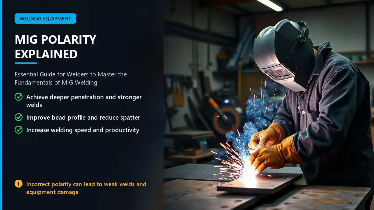
Polarity is the direction of electrical current flow through the welding circuit. That is the whole idea. Your welder has two output terminals, a positive one and a negative one, and the wire you feed through the gun plus the workpiece clamp are attached to them. Whichever terminal the electrode side is connected to defines the polarity of the arc. Connect the gun lead to the positive terminal and the clamp to the negative terminal, and you have electrode positive. Reverse those connections and you have electrode negative. Nothing about the machine changes internally in most units, only which stud the cables are bolted to, and therefore which way electrons travel across the arc gap.
Because the arc is a complete circuit, current leaves one terminal, crosses the atmosphere as plasma, enters the other side, and returns through the workpiece and cables. Break that loop anywhere and no arc exists. The direction you run it in changes where heat concentrates, how the wire melts, how hard the arc blows into the plate, and ultimately how the finished weld looks and holds up. Welders care about polarity for the same reason a plumber cares about which way a valve faces: the hardware is identical, but the result is not.
DCEP stands for Direct Current Electrode Positive. The electrode, which in MIG means the wire coming out of the contact tip, is hooked to the positive side of the machine, and the workpiece is negative. Older welders call this reverse polarity, sometimes abbreviated DCRP, because conventional current runs opposite to the old idea of “straight through” the electrode into the part.
DCEN stands for Direct Current Electrode Negative. The wire is on the negative side, the plate is on the positive side, and the old-school name is straight polarity, abbreviated DCSP. There is a handy memory trick: DCEN and DCSP both refer to the same setting, and the minus sign is just a straight line, so straight polarity means negative.
You will hear both the modern and the old terms used interchangeably depending on who trained the person next to you. A 55-year-old structural welder may say “it’s on reverse” while a newer fabrication manual says DCEP. They mean the same thing. The important part is that only two options exist on a DC MIG machine, and you can verify which one you have in about five seconds with a quick look at the terminals.
Most wire-feed welding uses DC rather than AC because direct current flows in one direction constantly, which gives a stable, predictable arc and a smooth metal transfer. Alternating current flips direction many times per second, sixty cycles per second in North America, which means the polarity of the arc changes one hundred and twenty times every second. That flip-flopping splits the available heat roughly fifty-fifty between the wire and the plate and tends to make the arc wander, a phenomenon called arc blow that can push the puddle off the joint line.
AC still earns its place in other processes. TIG welding of aluminum leans on AC because the alternating cycle cleans the oxide layer off the surface while still putting usable heat into the plate, and certain stick electrodes are designed only for AC. A handful of specialized MIG machines can output AC for aluminum work, and research into AC GMAW continues for its ability to control heat input on thin sections. But walk into almost any fab shop and the MIG welder will be a DC machine set to DCEP, running solid wire with a shielding gas mix. If you want to read more about that, our piece on whether MIG welding is AC or DC digs into the current types in more detail.
Think of the whole setup as a loop with the machine in the middle. Out of the positive terminal runs the gun cable, through the trigger switch, down the liner, through the contact tip, into the wire, across the arc, into the plate, back through the work clamp, and home to the negative terminal. Electrons physically travel from the negative side toward the positive side, while conventional current is described as flowing the opposite way. Both descriptions are correct viewpoints of the same physical event, which is why welding literature can seem contradictory until you check which convention the author used.
What matters at the puddle is simpler: the negative pole emits electrons across the arc gap, and the positive pole collects them. Where those electrons land is where the heat shows up. About two-thirds of the arc’s heat develops at the positive side, the anode, and about one-third at the negative side, the cathode. That single fact explains nearly everything you will ever notice about polarity, from why your wire melts at a certain rate to why the plate does or does not get hot enough to fuse.
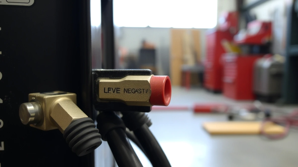
Quick Note: You do not need to disassemble anything to check polarity. Open the wire feed compartment or the side panel and look at which stud the work clamp cable is bolted to. Positive usually has a plus sign or a red boot, negative a minus sign or a black boot. If the gun lead is on plus, you are running DCEP.
Polarity makes more sense once you picture the machine it lives in. A MIG welder, formally gas metal arc welding or GMAW, does four jobs at once: it pushes a consumable wire out of a spool at a chosen speed, meters a shielding gas over the weld zone, applies welding current between the wire and the part, and lets you steer the arc by hand. The wire is both the electrode that carries the current and the filler metal that becomes the weld. That double duty is exactly why heat distribution matters so much, as we will get into shortly.
You pull the trigger, the drive rolls spin, and wire crawls out of the gun at a speed you set in inches per minute. Gas flows from the cylinder through the same hose, out the nozzle, and blankets the puddle so atmospheric oxygen and nitrogen cannot contaminate the molten metal. When the wire touches the plate, short-circuit transfer happens, the circuit closes, and an arc flashes. The wire melts into droplets that transfer into the puddle, and you move along the joint leaving a fused trail of metal behind you. On mild steel with a 75 percent argon, 25 percent CO2 mix, you will typically run somewhere between 18 and 26 volts depending on thickness, with wire feed speeds from about 150 to over 400 inches per minute for a range of plate from sheet metal to 3/8-inch stock.
Two transfer modes dominate short-circuit MIG work. Short-circuit transfer is the fine-wire, lower-heat mode where the wire touches the puddle dozens of times per second; it is ideal for thin material and out-of-position work. Spray transfer happens at higher voltage and wire speed when tiny droplets stream across the arc continuously, giving deep penetration and a fluid puddle that is great for flat-position fillets on thicker steel. The polarity stays DCEP in both modes for solid wire, but the way the arc behaves changes dramatically with your settings. If you are still learning to read those settings, our guide to using a MIG welder as a beginner walks through the knobs one at a time.
On a typical hobby or light-industrial MIG machine, polarity is set at two output studs, usually inside a small access door on the front of the power source. One stud has the gun cable attached, the other has the work clamp cable. Some machines, particularly units designed to switch between solid wire and flux-core wire, use polarity changeover terminals with quick-connect lugs so you can move the gun lead in seconds without tools. A few upmarket machines and many industrial wire feeders have a polarity reversing switch on the front panel or use internal contactors so the operator changes polarity without touching a cable at all.
Whichever style you own, the machine itself does not care. There is no polarity sensor judging your choices. It simply delivers current to whichever terminal you connect. That means the responsibility for running the correct setting sits squarely with the operator, along with the habit of re-checking it whenever the machine changes hands, returns from a repair, or comes off a job where it ran flux-core wire. Our related article on the MIG welder wire feed motor covers the drive side of the machine if you want the full picture of what happens when you squeeze the trigger.
Wire-feed welders run on constant voltage power, which means the machine works to hold your voltage setting steady no matter how the arc length wiggles. In practice, the voltage knob is really an arc length knob: turn it up and the arc gets longer, hotter, and wider; turn it down and the arc shortens and tightens. The wire feed speed knob is effectively your amperage control, because the machine will push whatever current is needed to melt the wire at the rate you are feeding it. Faster wire equals more amps. That relationship is why polarity interacts so directly with your settings, since the heat split across the arc either helps or fights whatever amperage you choose.
A rough rule of thumb that has survived decades of shop use is that you get somewhere near one amp of welding current for every inch per minute of wire feed on mild steel, though the exact ratio varies with wire diameter, alloy, and gas. Feeding 0.030 wire at 250 inches per minute lands you in the neighborhood of 200 to 230 amps, plenty for a solid 1/4-inch fillet in the flat position. Cross-check any number you dial in against a chart like our MIG wire speed and voltage chart, then confirm it with a test bead.
Pro Tip: Label your cables with white electrical tape marked plus and minus the first time you verify polarity. It takes thirty seconds, and it saves the whole shop from guessing every time somebody swaps leads for a flux-core job.
Polarity is not a personality preference. It is a process variable with direct, measurable consequences for the weld, and the consequences show up in four places: how deep the weld fuses, what the bead looks like, how stable the arc stays, and how fast you can move. Miss it and every one of those suffers at the same time, which is why wrong polarity feels like five problems instead of one.
Penetration is the depth the weld metal bites into the base metal, and it is the single most important mechanical property of a joint. A weld sitting on the surface with a pretty ripple pattern but no root fusion will crack the first time the part sees real load. When MIG polarity is correct, the arc force concentrates where it belongs and the wire melts at a rate matched to the current, producing a weld that ties in at the toes and reaches the depth your material thickness demands.
Run the polarity backwards and penetration drops noticeably at the same settings. The plate does not get the arc energy it expects, the wire melts unevenly, and you end up with what inspectors call overlap or cold lap, where the weld metal rolls over un-fused base metal instead of wetting into it. On a static bracket that might hold for years. On a trailer frame, a hitch, or anything that carries people, it is a failure waiting for a bad road. This is also why penetration questions come up constantly in conversations about whether MIG welding is strong as a process: the answer depends far more on setup and execution than on the brand of machine.
The shape of the finished bead, its width, height, and how smoothly it blends into the plate, is heavily influenced by polarity. Correct polarity produces a puddle that wets out at the toes, leaving a flat to slightly convex profile with tight, consistent ripples. Wrong polarity tends to give you a narrow, tall, humped bead that stands proud of the surface, or in bad cases a lumpy rope that looks like it was laid on rather than in. If you are welding something visible, a handrail, a stainless counter, a restored car panel, bead appearance is often the first thing anyone notices, and no amount of grinding fully hides a bead that was never fused properly.
Appearance and strength are not separate topics either. The same wetting action that makes a bead look smooth is what eliminates the sharp notches at the weld toe where cracks like to start. When you see a gorgeous, flat, evenly rippled MIG bead, you are usually looking at a sound weld, and a proper polarity setup was one of the reasons it came out that way.
A correctly polarized MIG arc has a characteristic sound, a steady, crisp fry that tells an experienced ear that the arc is stable and the transfer mode is right. Wrong polarity makes the arc sputter, sizzle inconsistently, or stutter as the wire stubs into the puddle. Instability does not just look bad, it slows you down. You travel more conservatively, you stop to chip spatter, you re-weld problem areas, and your deposition rate, the pounds of metal you actually place per hour, falls off a cliff.
Stable arcs also let you push travel speed to the higher end of the acceptable range, which reduces total heat input into the part. Lower heat input means less distortion on thin assemblies and less chance of overheating heat-sensitive alloys. In production environments where operators are paid by the completed assembly, an hour of lost productivity per shift from a badly set machine adds up fast. Correct polarity costs nothing and gives that time back.
Short Note: Listen to your arc during the first inch of every new setup. A smooth, even crackle with minimal popping usually means polarity and settings are in harmony. A harsh, erratic snap with visible spatter is your cue to check the terminals before touching anything else.
Everything up to this point leads here. The two polarities are not variants of the same thing, they are opposite operating modes with genuinely different behavior. The table below is the fastest way to see the split, and after it we will unpack each row so the numbers mean something at the bench.
| Characteristic | DCEP (Reverse Polarity) | DCEN (Straight Polarity) |
|---|---|---|
| Electrode connection | Wire/gun lead on positive | Wire/gun lead on negative |
| Workpiece connection | Negative | Positive |
| Electron travel | From workpiece across the arc to the wire | From wire across the arc to the workpiece |
| Heat distribution | About two-thirds at the wire, one-third at the plate | About two-thirds at the plate, one-third at the wire |
| Arc character | Concentrated, forceful, digging | Softer, wider, gentler |
| Typical MIG use | Solid wire GMAW, gas-shielded flux core, most stainless work | Many self-shielded flux-core wires, MIG brazing, some thin or heat-sensitive work |
| Penetration pattern | Deeper, narrower fusion profile | Shallower, wider surface fusion |
| Old-school name | Reverse polarity, DCRP | Straight polarity, DCSP |
Here is the physics in one paragraph. The negative pole of the arc emits electrons and the positive pole collects them, and the energy released when those electrons land at the positive terminal produces most of the arc heat. Roughly two-thirds of the heat develops at the anode, the positive side, and one-third at the cathode, the negative side. On DCEP the wire is the positive side, so the wire soaks up the lion’s share. On DCEN the plate is positive, so the plate soaks it up instead. That flip is the whole difference in one sentence.
This heat split is exactly why consumable-electrode processes prefer DCEP. In MIG, the wire has to melt continuously at hundreds of amps worth of equivalent current while also traveling through a liner, a gun, and a contact tip that all need to survive. Give the melting job to the side of the arc that naturally produces more heat and everything runs cooler and smoother on the equipment side. For the long-form explanation of anode heat, electron emission, and why the split lands near two-thirds, the welding power chapter of this open educational welding textbook from the Washington State Board for Community and Technical Colleges lays it out cleanly.
DCEP is the workhorse setting for solid-wire MIG because it delivers deep, reliable fusion at normal shop settings. The concentrated arc blasts into the plate root while the molten droplets carry additional heat into the puddle, and the result is a weld with real throat thickness and good root bite. This is the mode you want for structural brackets, frame repairs, and anything over about 1/8 inch thick where fusion matters more than surface appearance.
DCEN softens the arc. More of the raw heat lands directly on the plate surface, but the arc is less forceful and the wire melts more slowly, so overall penetration ends up lighter and the bead tends to sit wider and flatter. That profile has genuine uses: thin sheet that would otherwise blow through, copper and brass work where you want surface wetting without deep fusion, and the MIG brazing processes that use silicon bronze or aluminum bronze filler. It is also the polarity many entry-level machines ship with when they are configured for gasless flux-core wire, which is a large part of why people accidentally run solid wire backwards in the first place.
Choose DCEP for solid wire with shielding gas on steel or stainless, for gas-shielded dual-shield flux-core wire, for spray transfer on thick sections, for vertical-up work where you need confident root fusion, and for the overwhelming majority of jobs a general fabrication shop sees. If you own one MIG welder and mostly weld steel, DCEP should be where it lives ninety percent of the time.
Choose DCEN when the wire manufacturer says so, and this is the part people get wrong. Polarity requirements vary by consumable. Self-shielded flux-core wire, the kind that runs without a gas bottle, is commonly specified for electrode negative on many product lines, and industrial practice varies with wire design; some self-shielded wires call for electrode positive and some for electrode negative depending on the classification. Gas-shielded flux core almost always wants DCEP. MIG brazing filler wires, copper-based surfacing work, and certain aluminum processes also live on DCEN. The wire box and the manufacturer datasheet are the final authority, not the habit of whoever set the machine up last. For a deeper look at the flux-core side of this, read our dedicated guide on flux-core welding polarity.
One more cross-process reminder worth remembering: polarity is not universal across welding processes even on the same machine. TIG on steel runs DCEN with the tungsten negative so the non-consumable electrode stays cool, stick welding commonly runs DCEP for deep penetration, and gouging often runs DCEP as well. If you switch processes on a multi-process unit, assume the polarity changed until you verify it. Miller Electric’s engineering team published a useful overview of welding polarity and modern switching systems that covers the same principle from the manufacturer’s side.
Quick Note: Wire type beats habit every time. The rule that works on 95 percent of jobs is solid wire equals DCEP, but the remaining five percent will wreck a weekend. Read the spool label or the spec sheet before you assume.
You do not need an engineering degree to understand arc polarity, but you do need a couple of basic ideas locked in, because they let you diagnose weird arc behavior without guessing. This section builds the model in layers, starting from atoms and ending at the puddle, and it stays practical the whole way through.
Electric current in a welding circuit is a stream of electrons moving through conductive material. Copper cable, steel plate, and the welding wire are all conductors because their atoms hold their outer electrons loosely enough to let them drift from atom to atom. Apply voltage from the power source, give the electrons a path, and they move. The atmosphere between the wire and the plate is not a conductor under normal conditions, so the electrons cannot simply jump the gap until the wire gets close enough to touch or the voltage ionizes the gas into plasma. Once that plasma channel forms, you have an arc, and the arc carries current at the thousands of amps per square inch densities that melt steel.
The magnetic field around the moving charge also matters. It pinches the arc column into a cone shape and helps blow the plasma toward the plate, which is one reason arc force contributes to penetration independent of raw heat. When welders describe an arc as “digging” or “soft,” they are describing the combined effect of this force plus the heat distribution we covered above.
When electrons slam into the positive terminal, their kinetic energy converts to heat along with the energy released by the work function of the metal surface. Meanwhile the negative terminal has to spend energy pulling electrons out of its surface, which offsets part of the heat generated there. The net result in a welding arc is a heat split of approximately two-thirds at the positive side and one-third at the negative side. It is not perfectly constant, it shifts a little with gas mixture, current level, and electrode geometry, but two-thirds and one-third is the working number taught in welding programs and used in day-to-day setup reasoning.
Flip the polarity and you flip the split. That single flip changes where your wire melts fastest, how hot the plate surface gets, how the puddle flows, and how much of your current setting ends up as useful fusion rather than wasted surface heat. When someone says polarity is the most underrated setting on a MIG welder, this is what they mean.
Counterintuitive as it sounds, you want most of the arc heat on the electrode in a consumable-wire process. The wire must melt at exactly the rate it is fed, hundreds of times per minute in short-circuit transfer, while the plate only needs enough heat to melt a localized pool at the joint root. Put two-thirds of the heat on the wire, as DCEP does, and you get fast, clean melt-off, a stable arc because the wire end is always at the right temperature, and a plate that heats gradually enough to fuse without blowing through. Put two-thirds on the plate instead and the wire melts slowly relative to its feed rate, the arc starts stubbing and popping, and the plate overheats in a narrow band while the filler fails to blend.
This balance is also why simply cranking wire speed to compensate for wrong polarity never really works. You are trying to fix a thermodynamic mismatch with a mechanical adjustment, and while you can force something resembling a weld out of the machine, the arc will never be as stable or the deposition as efficient as it would be with the terminals swapped correctly. Fix the polarity first, then tune voltage and wire speed for the joint in front of you.
Pro Tip: If your first pass of the day behaves strangely and every setting looks reasonable, stop troubleshooting the knobs and check the two cables. Polarity mistakes take ninety seconds to fix and can save an afternoon of chasing a phantom problem.
Once you understand what polarity does, choosing it becomes a short decision tree rather than a mystery. Six variables drive the answer, and in most cases three of them will be obvious within a minute of looking at the joint. Walk through them in order and you will pick correctly every time.
Carbon steel with solid wire is the default case and runs DCEP. Stainless steel also runs DCEP, though gas selection changes more than polarity does on stainless work. Aluminum has its own rules because of the tough oxide layer that forms on the surface, and depending on the machine and filler it may run on DCEP with argon, on AC with a dedicated unit, or through a spool gun set up for the process. Copper, bronze, and brazing filler metals frequently prefer DCEN because you want surface wetting without aggressive digging into the base metal.
Read the metal first, then the wire, then the machine. An alloy the wire manufacturer flags as heat-sensitive, such as certain nickel alloys or thin-gauge coated steels, may call for a polarity and settings combination that reduces total arc energy. Our piece on welding gas for aluminum covers the shielding side of that equation.
Thin material punishes excess heat and thick material punishes insufficient fusion, and polarity shifts your position on that spectrum. On 16-gauge to 1/8-inch sheet, the priority is controlling heat so you do not blow through, and the temptation to switch to DCEN for a softer arc is real. On anything from 1/4 inch up, or on any joint that will carry a load, DCEP gives you the penetration you need without forcing you to crawl along the joint at half speed. Short-circuit transfer is generally not recommended beyond about 1/4 inch thickness, so past that point you move to spray transfer on DCEP with higher settings.
Position joints also interact with thickness. A 3/16-inch lap welded flat at high speed is a different heat problem from the same lap welded overhead, and polarity stays constant while your other settings adjust around it. Getting that balance right on thin material is covered in depth in our guide to welding thin metal.
Gas and polarity work as a team. A 75/25 argon-CO2 blend on mild steel gives a stable arc on DCEP with a nice balance of penetration and low spatter. Pure CO2 runs hotter and deeper on DCEP but throws more spatter. Tri-mix gases with helium and oxygen are tuned for stainless and structural work and assume correct polarity. Argon-rich mixtures used for spray transfer only behave properly on DCEP with the wire speed and voltage to support that mode. Gasless flux-core setups bring polarity into the equation more forcefully because the wire’s flux chemistry was designed around a specific current direction.
Since gas choice and polarity both affect puddle fluidity and cleaning action, change one variable at a time when you are dialing in a new material. Our article on MIG welding gas settings pairs well with this section.
Flat and horizontal positions give you the most freedom because gravity helps the puddle wet out. Vertical-up requires enough penetration to fuse into the root while the puddle freezes below you, and DCEP delivers the arc force that makes vertical-up fillets possible. Overhead work demands restraint, and while polarity typically stays the same, your voltage and wire speed come down to keep the puddle from sagging. The practical takeaway is that position rarely flips polarity, but it amplifies whatever mistake you already made with it.
This is the variable that overrides the defaults. Solid MIG wire, the copper-coated steel wire in a sealed spool, is DCEP across the board. Self-shielded flux-core wire frequently runs DCEN, and in industrial settings operators switch polarity when they change wire classes, for example moving from an electrode-positive wire for flat work to an electrode-negative wire for out-of-position welding. Gas-shielded flux core is normally DCEP. Aluminum wire, stainless wire, silicon bronze, and copper-coated MIG wires all carry their own published recommendations. Wire diameter affects the settings more than the polarity, but a heavier wire demands a motor and drive system that can keep up, which is the subject of our piece on the wire feed motor.
Rule of thumb worth tattooing on your toolbox: solid wire equals electrode positive, self-shielded flux core equals check the box, gas-shielded flux core equals electrode positive. Never take the third one on faith without confirming, because exceptions exist.
Polarity affects how fast you can move. A stable DCEP arc with proper penetration lets you travel at a brisk, confident pace because the puddle is behaving. Wrong polarity forces you to slow down in hopes of buying more heat input, which ironically makes the bead worse because slower travel piles more metal into a narrower area. Match your speed to the joint after the polarity is correct, then fine-tune with voltage and wire feed speed. Our selection of MIG wire options includes diameter and alloy guidance that pairs with speed settings.
Quick Note: When two variables disagree, follow the consumable manufacturer first, then the machine manual, then general shop rules of thumb. Spool labels and datasheets exist because the wire makers tested the combination.
The same polarity setting does not treat every metal equally, and the differences are worth understanding before you commit to a pass on something expensive. Here is how the big three break down in real shop work.
Mild steel is where DCEP has reigned for decades and where it performs best. With 0.030 or 0.035 solid wire and a 75/25 argon-CO2 mix, a typical DCEP setup for 1/4-inch plate lands around 22 to 24 volts with wire feed speed in the 350 to 420 inches-per-minute range, giving good penetration with manageable spatter. Drop to 1/8 inch and you are nearer 19 to 21 volts at 200 to 260 inches per minute. Those numbers are starting points, not commandments, but they only work with the polarity set correctly. On a machine that has been left in DCEN from a flux-core job, those same numbers will under-penetrate and spray spatter.
Stainless also runs on DCEP with solid stainless wire, but it is fussier about gas and heat. Common shielding choices are argon with 1 to 2 percent CO2, or argon with a little oxygen, and heat input needs to stay low enough to avoid sugaring and excessive oxidation while still fusing properly. Correct polarity keeps the arc tight and the puddle controllable, which matters when you are trying to keep the heat-affected zone narrow on a visible weld. If you are joining stainless with a wire-feed process for the first time, our article on MIG welding stainless steel covers gas, settings, and technique together.
Aluminum is the material that breaks the simple rules. The oxide layer on aluminum melts around 3,700 degrees Fahrenheit while the aluminum beneath melts near 1,220, so you need enough cleaning action to strip the oxide as you weld and enough heat to fuse the metal without blowing through. Dedicated aluminum MIG setups often use 100 percent argon with DCEP or AC output, a short gun or spool gun to reduce wire push resistance, and larger wire such as 0.035 or 0.047 to feed reliably. On a standard DC machine, DCEP with argon is the usual configuration, and the cleaning action at the workpiece side of the arc helps break up oxide. AC adds a cleaning cycle that many welders prefer on dirtier material. Polarity mistakes on aluminum show up quickly as dirty, porous beads that refuse to wet out.
The wire feed system gets a workout on aluminum too, because soft aluminum wire kinks and slips far more easily than steel. Technique matters just as much as the arc settings, and our guide on MIG welding aluminum without gas plus the aluminum welding notes in our MIG exhaust welding walkthrough both have practical setup advice.
Galvanized steel burns off its zinc coating in the arc and produces fumes that demand good ventilation, and the coating also destabilizes the puddle slightly. Correct polarity keeps the arc firm enough to burn through the coating and still fuse the steel underneath, while a backwards setup turns an already messy job into pure frustration. Copper-bearing steels, painted or oiled sections, and mill-scale-heavy plate all behave better when the arc is doing what it is supposed to do. For galvanized work specifically, see our notes on welding galvanized steel with MIG, and keep ventilation and fume control in the plan, which the NIOSH welding hazards guidance covers from the health side.
Pro Tip: Write the polarity on your setup card next to the gas and wire for every material you weld regularly. Stainless, aluminum, and steel cards should each carry their own line so a borrowed machine cannot sabotage the job.
Wrong polarity rarely announces itself with an error code. It shows up as a collection of symptoms that each look like a settings problem, which is exactly why people chase them in circles. Here is the full catalog of what goes wrong, and what each symptom is really telling you.
The most visible symptom is a shower of small molten balls that stick to the plate, the gun, the nozzle, and anything within a foot of the weld. Some spatter is normal in short-circuit transfer, but a sudden jump in spatter volume with no change in wire or gas is a classic polarity signal. When the wire does not melt at the rate it feeds because the heat split is wrong, large droplets form and detach violently, throwing molten metal outward. You will also see spatter build up inside the nozzle, which then disrupts gas coverage and makes the problem worse in a feedback loop.
Spatter is not just an aesthetic complaint. It costs grinder time, it ruins coatings you already applied, and it lands hot metal on nearby surfaces including your skin and your lens. Getting polarity right typically cuts spatter dramatically before you touch any other setting. If spatter persists after polarity is confirmed, our guide on reducing flux-core spatter has a checklist of secondary causes.
The quiet symptom is the dangerous one. A weld can look acceptable from the surface while having almost no fusion at the root, a condition called cold lap or lack of fusion. Wrong polarity reduces arc force at the plate, and since penetration is invisible without cutting and etching a test coupon, this failure mode hides until the part is in service. Warning signs you can see include weld toes that sit on top of the plate with a visible shadow line underneath, a bead that stays narrow and tall, and spatter balls stuck at the edges rather than a smooth tie-in.
If you are welding anything structural, take the extra five minutes to cut a sample and check penetration on a scrap piece of the same thickness before running the real joint. That habit catches polarity errors immediately and builds the kind of judgment that separates someone who sets a machine by feel from someone who knows their weld is sound.
Gas pores form when atmospheric contamination or unstable arc conditions trap gas in the freezing puddle. Backwards polarity destabilizes the arc and can disturb the gas envelope enough to introduce porosity, particularly when combined with a nozzle clogged with the spatter described above. The bead itself goes irregular, with wandering width, inconsistent ripples, and occasional craters at stops. Porosity is one of the most common reject reasons in welding inspection, and while it has many possible causes, polarity is one of the easiest to rule out. We break down the full range of causes in our article on porosity in welding.
At the beginning of a weld, wrong polarity makes arc initiation feel wrong. The wire may stub into the plate repeatedly instead of establishing a clean arc, or the arc may start and extinguish in a stutter. On machines with a slow-start feature, the effect is masked for the first fraction of an inch and then shows up as the current climbs. Experienced operators describe it as the machine “fighting” them, and it often sends them reaching for the voltage knob when the real fix is at the terminals.
Important: Four symptoms, one root cause. Excessive spatter, shallow penetration, porosity, and hard arc starts are the classic quartet of wrong polarity. Check all four against your terminal connections before changing anything else.
Changing polarity is one of the simplest mechanical tasks in welding, which makes it all the more annoying when people avoid it. The whole job takes a couple of minutes with no special tools on most machines. Follow the sequence below and you will never second-guess the result.
Power down the machine and unplug it or switch the main disconnect off. Open the front access panel or wire feed compartment and look for two output studs or quick-connect terminals. On many units they are labeled with plus and minus symbols or sit under red and black covers. One has the work clamp cable attached, the other has the gun cable. If your machine has a polarity reversing switch instead of terminals, you can skip the manual swap entirely and simply flip the switch with the machine powered off.
Loosen the nut or release the quick connect on the gun lead and move it to the opposite stud, then do the same with the work clamp lead so the two have traded places. Tighten both firmly, because a loose connection adds resistance, generates heat, and will cause the exact kind of intermittent arc problems you are trying to avoid. Reinstall any covers, then double-check by tracing each cable from the stud to its end: gun cable on positive means DCEP. Mark the cables with tape if your machine gets used by multiple people.
Modern machines increasingly handle this for you. Some units have a front-panel switch that toggles between solid wire and flux-core modes and sets polarity internally. Industrial systems from manufacturers like Miller offer remote polarity reversing, where the operator changes polarity at the wire feeder with a button press and the machine does the switching internally, eliminating the walk back to the power source entirely. That technology exists because polarity changes are frequent on real jobsites and because cable swaps create wear and trip hazards over time. Whether your machine has the feature or not, the underlying requirement is identical: the consumable you feed must receive the polarity it was designed for.
Quick Note: Make the polarity check the final step of every machine setup, right before you strike the arc. Terminal check, wire check, gas check, ground check, then weld. Twenty seconds, every time.
Experienced welders do not trust a setup until the arc has proven it on metal. A structured test sequence takes ten minutes, uses almost no material, and gives you certainty instead of optimism.
Use a piece of the same alloy, the same thickness, and ideally the same surface condition as your real workpiece. Test on clean mill scale steel with a piece of clean stainless and you will learn nothing about the stainless weld. Run a bead about four inches long, then a fillet between two pieces if the joint you are building is a fillet. Match the joint geometry because heat sinking differs between a flat plate and a T-joint, and polarity errors show up differently in each.
Cut the coupon if the joint is critical, or at minimum examine the bead and the heat tint around it. A correct setup gives even ripples, a smooth tie-in at both toes, minimal spatter, and visible fusion at the root when you break or cut the sample. A wrong polarity shows up as a tall narrow bead, spatter clinging to the plate, toes that sit proud instead of blending, and a shallow or absent root penetration when you section it. Photograph your results if you are testing several settings so you can compare objectively rather than from memory.
After confirming polarity, tune the two knobs that matter. If the bead is too narrow and high, add voltage to widen and flatten it. If penetration is insufficient on thicker stock, raise wire feed speed to push more amps, or increase travel time by slowing your hand slightly. If the plate is blowing through, reduce wire speed first and voltage second. Keep contact tip to work distance in the quarter-inch to half-inch range, because an oversized stick-out changes effective current at the arc and will fool you into blaming the wrong variable. Every change you make should be small enough that you can attribute the improvement to the specific adjustment.
Once a combination works, write it down: material, thickness, joint type, wire, gas, polarity, voltage, wire speed, and travel angle. Over a year that notebook becomes the most valuable tool in your shop, because the answer to “what did I run on that job last spring” takes ten seconds instead of an afternoon of trial welds. Many welders keep it on their phone now; the medium matters less than the habit. Charts like our MIG wire size chart give you starting numbers, but your own notebook gives you proven ones.
Pro Tip: Test polarity changes with the exact gas flow rate you will weld at. Cranking the regulator up during a test and forgetting to dial it back masks how much of your improvement came from gas coverage rather than the swap.
Polarity is the foundation, but the finished weld is a balance between two competing demands: enough heat to fuse deeply, and not so much that you distort or burn through the part. Once the terminals are right, this section is about finding the middle.
Symptoms include burn-through on sheet, a bead that is excessively wide and flat, heavy heat tint on stainless, and visible distortion where the plate has pulled out of flat. Remedies, in order of preference: reduce wire feed speed, reduce voltage slightly, increase travel speed to spend less time on any given spot, and only then consider whether the polarity choice itself is wrong for the material. On thin stock, moving from DCEP to DCEN reduces arc force and can save a delicate joint, but confirm that the wire you are running accepts electrode negative first.
Heat input also depends on joint design. A tight fit-up concentrates heat, while a wide gap needs more filler and more total energy. Tack accurately, keep root openings tight, and you will find you need less from the machine than you expected.
Symptoms: cold lap, a bead sitting on the plate, spatter that will not wet in, and a puddle that stays put rather than flowing toward the toes. Remedies in order: confirm polarity, increase wire feed speed for more amps, add a little voltage to lengthen the arc and widen the puddle, slow your travel speed slightly, and shorten an excessive stick-out. Increasing gas flow will not fix this problem no matter how tempting it feels. If the joint still refuses to fuse, the plate may be contaminated, the ground clamp may be poor, or the machine may be underpowered for the thickness you selected.
The sweet spot shows up as a puddle that stays fluid and responsive without sagging, a bead roughly one to one-and-a-half times as wide as the wire buildup is tall, toes that blend smoothly, and a heat-affected zone narrow enough that the plate stays in alignment. Work toward that target by adjusting one variable per pass and keeping notes. Over a few sessions you will start recognizing it by feel, hearing the arc settle into that steady crackle and seeing the puddle mirror flatten out. That instinct is worth developing because it lets you catch setup errors in the first inch instead of at the end of the joint.
Short Note: Balance is a moving target. The same polarity and settings that are perfect on a bench test can be wrong on the real assembly because the ground clamp location, heat sinking, or joint fit-up changed. Test where the work will actually be welded whenever you can.
Polarity is usually discussed as a quality issue, but it has a safety dimension too, and it is one of the more overlooked connections in day-to-day shop work. Three risk pathways link bad polarity to injuries and failures.
Excessive spatter is molten metal traveling at speed. It lands on forearms, drops inside collars, embeds in leather, and ricochets toward anything reflective. Eye protection rated for welding is non-negotiable, but a helmet with an auto-darkening lens only protects what it covers, so a neck strap, sleeves, and a cap matter more when spatter volume is higher than it should be. The simple engineering control is eliminating the excess spatter source by verifying polarity before welding begins rather than working around it after the fact. Our roundup of MIG welding helmets covers lens options, and general shop practices in our welding safety tips resource round out the PPE checklist.
A loose or corroded terminal at the polarity changeover point adds resistance to a circuit already carrying hundreds of amps. Resistance generates heat, and heat at a connection point can melt insulation, damage the gun liner, or burn an operator who grabs a hot cable without thinking. Wrong polarity can also push components outside their intended thermal range, shortening the life of contact tips, nozzles, and drive components. Check connections for heat after each session during your initial commissioning of a machine, and build a habit of inspecting the terminals whenever you change polarity.
This is the hazard with the longest fuse. Cold lap and lack of fusion from incorrect polarity create a weld that passes a glance and fails a load. Structural failures injure people and destroy equipment, and because the defect is hidden, they tend to appear without warning. Welding operations in the United States fall under OSHA’s general requirements for welding, cutting, and brazing in 29 CFR 1910.252, which sets out ventilation, protection from radiation, and safe practices for hot work. OSHA’s broader welding and cutting topic page is a good starting point for compliance questions, and the National Fire Protection Association publishes the NFPA 51 fire-prevention standard that governs hot work in many facilities. None of those documents mention polarity specifically, but the professional obligation to produce sound welds is the reason the detail matters.
Practical controls are simple. Verify polarity during machine setup. Label cables. Restrict polarity changes to people who have been shown the procedure. Keep a setup checklist at the machine that includes polarity, gas, wire, and ground. When a welder is pulled off a job and someone else steps in, the checklist prevents the silent handoff error that causes most of these incidents. Add a first-article test bead whenever the machine changes configuration, and you have closed the loop.
Important: A hot cable is a warning sign, not a normal condition. If a terminal, clamp, or gun handle is too warm to hold comfortably right after welding, shut down and inspect the connection before continuing. Heat at a connection is almost always a loose or corroded joint.
Setting polarity correctly on day one means nothing if the circuit degrades over the following months. A maintenance routine keeps the electrical path clean and the settings trustworthy, and most of it fits into a five-minute weekly check.
Inspect the full length of both welding cables for cracked insulation, exposed copper, kinks, and crushed sections. Look at the work clamp spring tension and the condition of its contact points, because a clamp that barely grips the plate forces current through a smaller area and heats up. Clean the terminal studs at the polarity changeover points until the metal is bright, and tighten them to the snugness specified in your manual. Oxidized copper looks dull brown or green; a wire brush or contact cleaner restores it in seconds.
The gun side of the circuit is the most neglected. Pull the liner occasionally and clean it, check the contact tip bore for erosion, and replace the tip when the hole becomes oval or oversized. A worn tip changes effective current at the arc and adds resistance that shows up as erratic feeding and heat buildup. Nozzle spatter should be cleaned out at every wire change rather than waiting until gas flow is visibly disturbed. These consumables are cheap and the arc quality difference is obvious.
Dust, grinding grit, and moisture on the machine’s ventilation paths cause the electronics and the feed motor to run hot, which over time can shift output characteristics. Blow out the machine on a schedule, keep the area around the wire spool clean, and make sure the drive rolls are not packed with wire dust. Periodic calibration against a clamp-on ammeter at a known wire speed and voltage setting confirms the machine is delivering what the dial claims, which matters if you rely on recorded settings from your notebook. The Lincoln Electric resource library publishes maintenance guidance for wire feed equipment that aligns with these practices.
Drive rolls wear grooves into themselves over hundreds of pounds of wire, cables develop internal breaks that never show from the outside, and clamps lose spring tension. Replace on condition rather than on a fixed calendar, and keep spare contact tips, nozzles, and a spare liner on the shelf. A maintenance drawer that is stocked means nobody skips the replacement because the part is not available, which is how machines end up running for months in a degraded state that nobody attributes to a five-dollar component.
Quick Note: Add polarity verification to your weekly machine check, not just your initial setup. Someone else may have borrowed the welder, and cable swaps leave no visible trace once the covers are back on.
When a MIG setup misbehaves, a disciplined sequence beats random knob-turning every time. This routine isolates polarity first because it is the fastest variable to check and one of the most commonly wrong.
Run down this list before touching anything:
If two or more of these appear together, polarity is the prime suspect. If only one appears, work through the standard troubleshooting order: settings, then consumables, then ground and cable condition, then polarity.
That sequence covers 90 percent of polarity-driven problems. If the test bead still misbehaves after the swap, the cause lies elsewhere: contaminated wire, a kinked liner, a bad ground, incorrect voltage, or a machine fault. Our troubleshooting companion pieces, including flux-core troubleshooting fixes and the deeper dive in mastering the wire feed welder, walk through those secondary causes in detail.
Several other faults mimic wrong polarity closely enough to fool experienced welders. A starving gas supply from a nearly empty cylinder or a blocked nozzle causes porosity and rough beads. A poor ground clamp forces current through a small contact patch and makes the arc wander. A bent or kinked liner makes feeding erratic, which the arc experiences as instability. Drive roll tension set too low lets the wire slip, producing a feed rate that does not match the dial. And a worn contact tip with an enlarged bore changes the electrical contact point enough to matter. Check the easy physical items in the same session as your polarity verification, because they share the same five-minute window and they often arrive together.
Pro Tip: Keep a known-good spare cable set in the drawer. Swapping to it for a test pass isolates cable faults instantly and eliminates an entire category of guesswork.
Once polarity is correct, the rest of your technique can build on a stable foundation. This section collects the gains you should notice and how to protect them.
Consistency is the underrated benefit. A machine running the right polarity holds its settings better from pass to pass and hour to hour, because the arc is operating in the regime the wire and the power source were designed around. Operators report fewer mid-job surprises, less need to compensate with the knobs, and welds that come out the same on the last hour of a shift as they did on the first. Over a project with hundreds of inches of weld, that consistency is what separates a professional result from an optimistic one. It also shows up in inspection results, where clean root fusion and consistent throat thickness are the numbers that get signed off.
Good polarity settings give you the cosmetic finish without special technique. Welds come out with even ripples, narrow heat tint on stainless, minimal spatter to chip, and toes that need no dressing. Three habits keep it that way: keep the nozzle clean so gas coverage stays intact, maintain a steady travel angle of roughly ten to fifteen degrees of drag for short-circuit work, and hold a consistent stick-out. The arc does the rest. If appearance matters on the job, remember that the prettiest beads in the shop almost always come off machines that someone took thirty seconds to set up properly.
A stable arc lets you travel faster with confidence, and faster travel means less total heat into the part, less distortion to correct, and more completed joints per hour. Spatter cleanup drops to near zero. Wire consumption becomes predictable, which makes purchasing and inventory easier. On a production line or a busy fab shop, these margins compound. Welding productivity is where the American Welding Society focuses much of its industry work, and the American Welding Society publishes the structural codes and best-practice documents that define what a professional result looks like. For everyday gains, our collection of welding tips for beginners and experienced hands alike has more technique-level adjustments that stack on top of a correct polarity setup.
Short Note: Expect improvement immediately after a polarity correction at unchanged settings. If the weld does not improve, the polarity was not the problem, and you have at least eliminated one variable cleanly.
Abstract explanations stick better when attached to a story, so here are three situations that come up constantly in small shops, each with a different polarity lesson attached.
A customer brings in a utility trailer with a cracked tongue bracket. You load 0.030 solid wire, dial in 22 volts and 320 inches per minute for the 3/16-inch tubing, and the first pass looks tired: spatter everywhere and a bead that will not blend. Before you change a single setting, you open the panel. The gun lead sits on the negative stud because the machine ran flux-core on a farm job the week before. Both leads trade places, the connections snug down, and the second pass at identical settings runs like a different machine. Total downtime, four minutes. Had you instead spent an hour tuning voltage and travel speed around the wrong polarity, the customer waits longer, you burn more wire, and the weld still has questionable fusion at the root. The lesson: check polarity first, every time the machine has been used by someone else.
Cold, windy weather pushes a shop toward self-shielded flux-core wire for outdoor repairs. You swap the wire, change the drive roll groove to the knurled flux-core groove, turn off the gas bottle, and the wire manufacturer’s box clearly states electrode negative for this product. You move both leads to DCEN, run a test on scrap, and the bead comes out with the deep penetration and heavy slag coverage characteristic of the process. Three weeks later solid wire goes back in for indoor work, and the polarity must move back to electrode positive with the gas reconnected. This back-and-forth is exactly where mistakes breed, and it is why the setup checklist with a polarity line printed on it earns its space on the wall. It also illustrates the broader process comparison in our flux-core versus MIG showdown.
An aluminum security gate needs assembly, and the shop’s general-purpose MIG welder is set up for steel. The aluminum wire feeds poorly through a ten-foot gun, so a spool gun goes on, holding a small spool right at the handle. Polarity stays electrode positive on the DC machine, the gas switches to 100 percent argon, and wire speed drops because aluminum melts at lower current than steel. The first attempts show porous, dirty welds, and the cause turns out to be a combination of surface oxide that was not cleaned and a ground clamp attached to a painted post. Wire brushing the joint, moving the clamp to bare metal, and confirming polarity on the spool gun terminals brings the bead back to a clean, stacked-dime appearance. Aluminum punishes every skipped step at once, which makes it a great reminder that polarity is one link in a chain that includes cleaning, gas, grounding, and technique. Related reading on aluminum MIG setup covers more of that chain.
Quick Note: After any process change, run one test pass before committing the workpiece. The test costs a few inches of wire; the rework costs an afternoon.
Solid-wire MIG welding on steel and stainless uses direct current electrode positive, DCEP, also called reverse polarity. That is the default for spray transfer, short-circuit transfer, and virtually every general fabrication task done with gas-shielded solid wire. Flux-core wire is the main exception, with many self-shielded wires specifying electrode negative and gas-shielded flux core normally staying on electrode positive. When a machine ships from the factory configured for MIG with gas, it is set to DCEP, and that is where it should stay unless a consumable specification says otherwise.
No. Amperage, which on a wire-feed machine you control through wire feed speed, remains the primary driver of penetration depth. Polarity decides how effectively that amperage is applied, where the arc force concentrates, and how the wire melts relative to the plate. Think of amperage as the size of the fire and polarity as the direction the heat points. You need both right: the correct polarity with too little amperage still under-penetrates, and maximum amperage on the wrong polarity produces a messy, unstable arc with poor fusion at the toes. Set polarity first, then tune amperage and voltage for the joint.
Many hobbyists run solid wire with gas almost exclusively and never touch the terminals after setup, and that works fine as long as the machine is set to DCEP to begin with. The trouble starts the first time you buy a spool of gasless flux-core wire for outdoor work, borrow the machine to a friend, or service the unit. If you never change polarity, verify it anyway once a month and after any event that could have altered the connections. If you do switch processes, make the polarity swap part of the same task rather than something you will remember later, because you will not remember later.
Gas choice influences your voltage, wire speed, travel speed, and transfer mode, and it matters enormously for arc stability and cleanliness, but it rarely flips polarity by itself. The exception is process-driven: moving from gas-shielded solid wire to a gasless flux-core product changes both the gas and the required polarity at once, which is why people confuse the two. Handle them as a paired change on your checklist, bottle off or on, polarity swapped, correct drive roll installed, and correct tip fitted.
Verify it at initial setup, at every consumable or process change, whenever the machine returns from repair or from another user, and during a routine weekly or monthly machine inspection. In practice, checking takes less than ten seconds once you know where the terminals are, so err toward checking more often. The cost of looking is nothing; the cost of not looking can be a rejected weldment or a failed part.
Pro Tip: Photograph your correct setup with the panel open and keep the picture on your phone. Comparing reality to the photo takes two seconds and catches a swapped lead even when you are in a hurry.
Polarity is the setting with the highest ratio of consequence to attention. It takes one glance to verify, one minute to change, and it shapes penetration, bead profile, arc stability, spatter, appearance, and the structural integrity of everything you weld. The default answer for solid-wire MIG is electrode positive, DCEP, and if you take nothing else from this guide, take that. The exceptions all live on the consumable label, so when you load a new type of wire, read the box before you strike the arc.
The habits worth building are small. Label your cables. Put polarity on your setup checklist. Run a test bead after every change. Write down what works. Inspect your terminals as part of weekly maintenance. Those five actions cost almost nothing and they eliminate an entire category of mysterious arc problems, the kind that eat an afternoon and make you doubt settings that were never wrong in the first place.
From here, keep going on the connected details that decide how the arc actually behaves: your voltage and wire speed pair, the wire you feed through the gun, the motor pushing it, and the drive rolls gripping it. Polarity is the foundation, but a great weld is built by a whole stack of details working together. Set the terminals right, keep the machine clean, test before you commit, and the arc will reward you with welds that look as good as they hold. Happy welding.