MIG Basics: The Complete Beginner’s Guide to MIG Welding (Setup, Settings & Technique)
Learn MIG basics from scratch: how GMAW works, machine setup, wire and gas choices, transfer modes, technique, troubleshooting…
READ ARTICLE →There is a special kind of frustration that hits when your MIG welder dies halfway through a bead. Last Tuesday a buddy named Marcus dragged his 180-amp machine into my garage with a busted shelf bracket clamped in the vise, gun in hand, ready to finish the repair. He squeezed the trigger. The relay clicked, the fan spun, the arc lights flickered on for a split second, and then nothing. No wire. He squeezed again. Same silence. He tilted the gun, looked down the nozzle like it might confess, and asked me the question I hear a few times a month: why has the wire feed motor stopped working, and what did he do to deserve it?
Nothing, as it turned out. His motor was fine. A quick peek behind the drive roll cover told the story: the liner was packed with gray dust, the drive roll tension had been cranked to the point where the rolls were skating over the wire instead of gripping it, and the contact tip bore had worn into an oval that grabbed the wire like a wet noodle. Three cheap parts, twenty minutes of fiddling, and the machine fed wire like it was brand new. The motor had been blamed for a crime it never committed.
That is the pattern with wire feed problems. The motor is the obvious suspect because it is the thing that is supposed to move the wire, so when the wire stops moving, eyes land on the motor first. But in my experience the actual motor assembly fails far less often than the stuff around it: the drive rolls, the liner, the contact tip, the trigger circuit, the spool, and a handful of settings that quietly ruin feeding when nobody is watching. If you are standing in front of a MIG welder that refuses to push wire, you are dealing with a solvable puzzle, not a dead machine.
This guide walks through the whole thing from the ground up. We will start with what the wire feed motor actually does inside the machine and why its job matters more than most people realize, then work through every common cause of feed failure in the order I check them in real life: power and control wiring, drive roll setup, liner condition, contact tip wear, gun length and trigger trouble, wire condition, and machine settings. After that you get a step-by-step troubleshooting sequence you can run top to bottom, setup specs for rolls and liners, guidance on when the motor itself really has died, a maintenance schedule that keeps the problem from coming back, and answers to the questions people ask me in the shop. By the end you should be able to fix your own feeder, avoid the mistakes that cause most feed problems, and get back to laying clean beads without guessing.
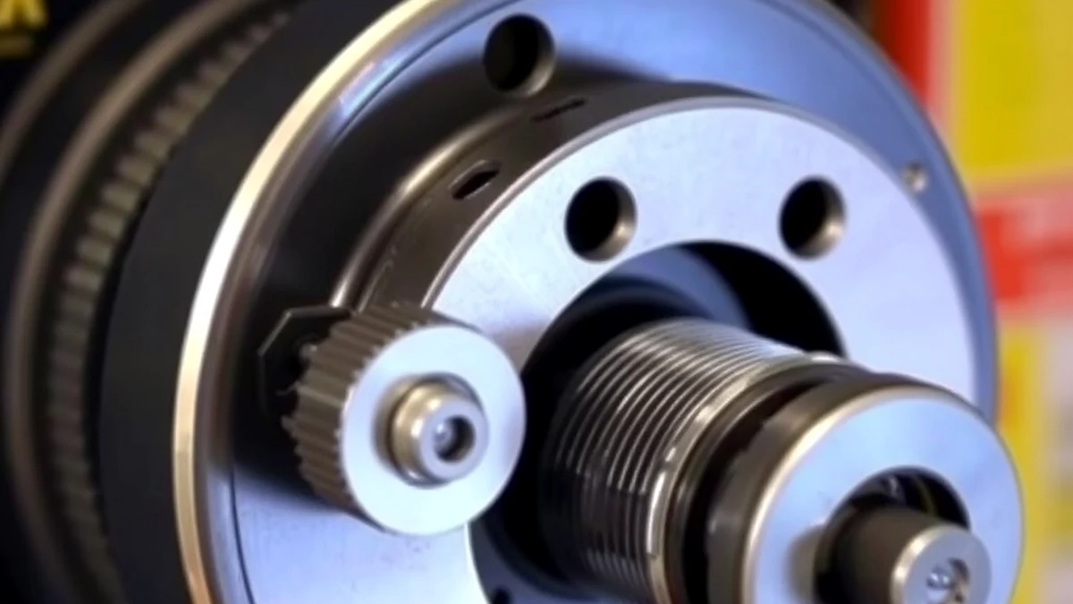
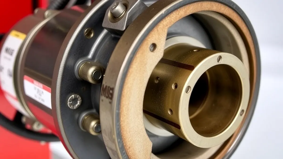
Before chasing symptoms it helps to understand the part everyone is blaming. The wire feed motor is a small DC electric motor, usually tucked inside the machine chassis or bolted to the wire drive assembly, and its only job is to spin a set of drive rolls at a controlled, adjustable speed. Those rolls pinch the welding wire and shove it down the gun liner at a steady rate. That is it. It does not know about voltage, it does not sense the arc, and it does not care whether you are welding quarter-inch plate or sheet metal. It just pushes wire at the speed you dial in.
What makes the motor matter is how many other systems depend on it. The control board uses the motor speed as one half of the welding equation. The trigger is a low-voltage control signal that wakes up the contactor, the gas valve, and the motor at the same moment. If any link in that chain breaks, the whole symphony stops, and the motor takes the blame even when the real failure is a two-dollar spade connector. Understanding each job around the motor is the fastest way to narrow down where the problem lives.
A MIG arc only stays stable when the wire arrives at the puddle at the same speed it is being consumed. Feed the wire too slowly and the arc burns back up into the contact tip, sputtering and popping. Feed it too fast and the wire stabs into the puddle without melting, stubbing and breaking the arc. The motor is what maintains that balance. On a decent machine the speed is regulated by a small control circuit that compensates when the rolls hit a heavy spot in the spool or when the liner drags in a long gun cable, so the wire keeps moving evenly even when resistance changes. When that regulation fails, you get the classic surge-and-stall pattern where the wire feeds in bursts.
Feed speed and arc voltage are tied together on nearly every MIG machine. Push the wire faster and the arc length shortens, which lowers effective voltage and makes the bead narrower and taller. Slow the wire down and the arc lengthens, voltage climbs, and the bead flattens out. The motor is the lever that moves voltage indirectly, which is why a sluggish feeder produces cold, ropey welds even when the voltage knob has not been touched. On older machines the feed motor circuit and the welding output share a control board, so a motor circuit fault can drag the whole machine into a fault state. That crossover is worth remembering when the welder powers up but refuses to strike an arc at all.

Wire feed speed is the primary control in GMAW. Voltage sets the heat, but feed speed sets deposition rate, penetration profile, and the overall rhythm of the weld. The numbers on the dial or the digital display translate to inches per minute of wire, typically ranging from about 60 ipm on small 110-volt machines up to 600 ipm or more on industrial units. If the motor cannot deliver the number on the display, every setting chart you follow becomes useless, because the machine is quietly welding at a different speed than you asked for. That is the hidden damage a failing motor does: it makes your settings lie to you.
Consistent feeding shows up directly in the finished weld. Steady wire means a steady arc, which means a uniform bead profile, even toes, and honest fusion at the root. Interrupted feeding means arc starts and stops, cold laps, spatter beads, and porosity from gas coverage disruption every time the wire hesitates. If you have been fighting porosity or spatter and cannot explain it, look at the feeder before you blame your gas mix or your technique. There is a reason feed problems head the troubleshooting list in most manufacturer service manuals, including those from Lincoln Electric and Miller Electric.
It sounds obvious, but people skip this: you cannot troubleshoot a system you do not value correctly. The wire feed assembly is not an accessory bolted onto a welder. It is half the process. In stick welding the electrode is the consumable and you control it by hand, so a machine with no feeder still welds. In MIG the wire, the current, the shielding gas, and the filler metal all arrive through one cable, and the motor is what moves all of it. No motor, no weld. Full stop.
There are four practical reasons to take the feeder seriously rather than treat it as an afterthought. First, it runs the welder: without wire moving, pulling the trigger accomplishes nothing regardless of how healthy the power section is. Second, it governs effective voltage through arc length control, which means feed problems masquerade as power supply problems. Third, it is the mechanism behind the single most important setting on the machine. Fourth, it protects quality, because every hiccup in feeding writes itself into the finished bead. Treat the feeder as a precision subsystem and you will diagnose twice as fast.
| Job of the Feeder | What It Controls | What Goes Wrong When It Fails |
|---|---|---|
| Runs the welding operation | Trigger circuit, contactor, gas valve, motor | No arc, no gas, no wire when trigger is pulled |
| Controls effective voltage | Arc length through feed rate | Cold joints, undercut, or burn-through on thin stock |
| Sets wire feed speed | Deposition rate and heat balance | Settings charts stop matching real results |
| Protects weld quality | Continuous arc and gas coverage | Porosity, spatter, inconsistent bead profile |
Quick Note: If your welder feeds wire only when you wiggle the trigger or hold the gun at a certain angle, you are looking at an intermittent electrical connection in the control lead, not a motor problem. Motors do not respond to cable positions; loose wires do.
Every feed problem announces itself in a specific way, and the pattern is a shortcut to the cause. I keep a mental checklist of five symptoms: no feed at all, intermittent feed, feed that works but slips, wire that feeds when the trigger is pressed but does not move when the arc should be running, and normal feeding with terrible weld results. Match your machine against this table first and you will usually skip half the diagnosis.
| Symptom | Most Likely Causes | First Thing to Check |
|---|---|---|
| Nothing happens when trigger is pulled | Blown control fuse, broken control lead, dead trigger switch, bad relay | Power at the wall, control fuse, trigger continuity |
| Motor hums but wire will not move | Drive roll tension too loose, rolls installed backwards, worn roll teeth, wire jammed at inlet guide | Drive roll cover and tension |
| Wire feeds in bursts then stalls | Clogged liner, kinked cable, tangled spool, weak motor brushes | Pull the gun cable straight and retest |
| Wire feeds with trigger but arc never starts | Gas solenoid stuck, bad ground clamp, contact tip blocked, wrong polarity | Ground clamp placement and tip condition |
| Feeding is fine but beads are ugly | Wrong feed speed for thickness, worn contact tip bore, incorrect voltage | Compare settings to a chart for the material |
| Motor keeps running after trigger release | Stuck relay, shorted control lead, failed trigger switch in closed position | Unplug the gun or disconnect control lead immediately |
That last row deserves emphasis. A motor that will not stop feeding will empty a whole spool through a hot gun in a couple of minutes, and a wire that keeps running out of a live gun is a burn and fire hazard. Disconnect power at the breaker before diagnosing a feeder that runs on its own.
Important: Never troubleshoot a MIG gun with the machine energized and the work lead connected. Turn the machine off, unplug it, and let stored energy in the capacitors sit for at least a minute before opening covers.
If the motor gets no electricity, nothing else matters. Control circuit faults are the first thing I rule out because they are fast to test and they account for a surprising share of dead feeders. The control side of a MIG welder runs on low voltage, usually 24 volts DC on modern machines, and it carries the signal from the trigger to the relay or contactor that switches the motor, the gas valve, and the welding output. A break anywhere in that path stops the motor cold while leaving the display lit and the fan running, which is exactly the confusing state that sends people down the wrong repair road.
The trigger switch is the most handled part on the entire welder, and it fails with regularity. Inside the handle, two small contacts open and close thousands of times. Eventually they pit, corrode, or crack, and the switch stops making a clean connection. The telltale sign is an intermittent feeder that responds to squeezing harder, holding the trigger at an angle, or wrapping the cable differently. A simple continuity test on the trigger wires with the gun unplugged from the machine tells you what you need to know in under a minute. The control lead itself can also break where it enters the machine or where it flexes at the gun handle, because that is where the cable bends most.
When the trigger tests good but the motor never spins, the next suspects are the control relay and the contactor. Listen closely when you squeeze the trigger. A solid click means the relay is engaging and the problem sits downstream at the motor or its wiring. No click at all points upstream: the control transformer, a blown low-voltage fuse, or the board itself. On some budget machines the relay contacts pit and weld themselves open after a few years of arcing, a failure mode that looks exactly like a dead motor. Replacing a relay costs a fraction of a motor, so rule it out first.
Gun adapters and quick-disconnect fittings are common on multi-process and industrial machines where guns get swapped frequently. A poorly seated adapter breaks the control circuit or the power path intermittently, producing a feeder that works on bench tests and quits in the middle of a job. Poor adapter connections also add resistance, which shows up as heat at the connector and a motor that slows under load. Check that the adapter pins are clean, fully seated, and locked. While you are there, verify the work cable connection at both ends. A weak ground makes the arc unstable and can mimic feed problems because the machine reacts to the voltage it senses.
Pro Tip: Pull the gun out of the machine and jump the control terminals together with a jumper wire for a bench test. If the motor spins steadily with the trigger bypassed, the gun lead or trigger is the fault. If it still will not spin, the problem is inside the machine.
Drive rolls are the hands that actually grip the wire, and they cause more feed failures than any other single component. A set of rolls costs less than a fast-food meal, yet wrong or worn rolls stop machines that are otherwise perfect. The physics is simple: the rolls must pinch the wire with enough force to push it against the resistance of the liner, without crushing it, and the groove must match the wire diameter closely enough that the wire cannot squash flat or slip through the gap.
Rolls are stamped with the wire size they were cut for, typically .030, .035, or .045 inch for steel wire, and metric equivalents elsewhere. Running .030 wire through .035 rolls leaves a gap the wire can flatten into as it passes through, which destroys diameter consistency and lets the wire skate under tension. The reverse is worse: forcing .035 wire through a .030 groove crimps the wire, leaves roll marks deep enough to jam at the contact tip, and can stall a healthy motor entirely. If the rolls are not marked or you inherited the machine, pull them and measure the groove with a caliper. My own rule is simple: match the roll to the wire, always. Charts like our MIG wire size chart give you the pairings most machines ship with.
Even with the right diameter, groove shape matters. V-grooves are the standard for hard wires like mild steel and stainless because the angled walls grip round wire firmly. U-grooves are designed for soft aluminum wire, which deforms under the point loading of a V and would otherwise get shaved. Knurled rolls exist for heavy flux-cored and metal-cored wires where extra grip helps push soft cored wire without crushing it. Using the wrong profile either slips or damages the wire, and both outcomes end at the same place: the feeder stops feeding. If you run aluminum regularly, our piece on drive rolls for flux core wire walks through groove selection in more detail.
Loose tension is the silent killer because the feeder still sort of works. The rolls spin, the wire creeps, and the machine feeds reliably until the gun reaches a curve or the liner gets a little dirty, at which point the wire stalls. Symptoms include wire that feeds freely with the gun straight but dies in position work, and rolls that spin while the wire stands still. If you can pull the wire through the gun by hand with the tension released and barely any drag when tensioned, the setting is too light for that wire size.
Over-tension is just as destructive. Crank the knob too far and the rolls dig into the wire, shaving off copper coating and packing the groove with flakes that reduce grip further. On flux-cored wire, excessive tension crushes the tubular profile, which weakens the wire and changes its chemistry at the point of contact. Worn rolls show the same effect with age: the groove profile rounds off, teeth on knurled rolls flatten, and grip fades no matter how tight you set the spring. Flip the rolls over and inspect the groove under light. A polished, mirror-bright groove with a visible step at the edge has reached the end of its life and needs replacing.
| Drive Roll Issue | What You See | Fix |
|---|---|---|
| Groove too large for wire | Flattened wire, copper flakes, slipping under load | Install rolls stamped for the wire diameter |
| Groove too small for wire | Deep score marks, jams at the tip, stalled motor | Step up to the correct roll size |
| V-groove on aluminum | Wire shaved flat, shredded coating | Switch to U-groove rolls |
| Tension too light | Rolls spin while wire sits still | Re-tension until wire cannot be slipped by hand |
| Tension too heavy | Copper dust in the cover, grooves polished | Back off to half turn past first grip |
| Worn rolls | Visible groove step, shiny mirror finish | Replace the set |
Short Note: Keep one spare set of drive rolls per wire size you use. Rolls are consumables like contact tips; swapping a fresh set every 10 to 20 pounds of wire restores feeding more often than any other single move.
The liner is a length of coiled steel, or sometimes nylon or Teflon, that runs inside the gun cable from the drive rolls to the contact tip. It is a guide rail for the wire, and it wears out. Because the wire drags against it constantly, a liner accumulates friction as it ages, and friction is the enemy of consistent feeding. A marginal liner feeds fine on a fresh spool in the flat position and quits the moment you go vertical or reach into a tight corner, which is why so many feed complaints arrive right when a job gets interesting.
Liners are sized to wire diameter, and the tolerance is tight. A .035 liner running .030 wire lets the wire wander and kink inside the cable, especially in long guns. A .030 liner running .035 wire adds drag everywhere and can stop the motor outright. Many manufacturers mark liner color-coding on the ends, but plenty of machines get the wrong liner installed during a repair. If your feeder has gotten suddenly worse after a liner replacement, measure the new liner against the wire before you dig any deeper.
Dirt enters the liner from three places: the wire itself sheds copper dust and drawing lubricant, the gas stream carries moisture and debris back through the diffuser, and the shop environment contributes grinder dust when spools are stored uncovered. Over a few hundred hours that debris compacts into a gray paste that behaves like sandpaper. The classic test is to remove the liner, hold it vertically, and drop the wire through it. It should slide through under its own weight with barely a whisper. If it sticks or needs a push, clean or replace it. Compressed air blows out loose debris, but a liner that has been dragging for months is better replaced than nursed.
Gun cables get dragged across concrete, run over by carts, and coiled tighter than the minimum bend radius permits. A kink in the cable kinks the liner inside it, creating a pinch point the wire must be forced through. The motor works harder, the wire polishes the kink, and eventually the wire bends at that spot and jams at the contact tip. You will notice the gun is stiff to move or that feeding changes when you flex the cable. Never store a MIG gun coiled in a tight circle; hang it or leave a generous loop.
Standard steel liners suit most steel and stainless applications. Aluminum wire is a different animal: it is soft, and it work-hardens and burrs when dragged against steel, so aluminum feeding calls for a nylon or Teflon liner with a graphite-impregnated surface. Put aluminum wire through a steel liner and you get shavings, jams, and a feeder that seems to fail randomly. Specialty liners also exist for long-reach guns, where the added drag of a 15-foot cable demands a lower-friction surface.
Quick Note: Blow out your liner with dry compressed air every time you change spools. It takes about ninety seconds and doubles the interval between replacements.
The contact tip is the last thing the wire touches before it becomes part of your weld, and it wears out faster than almost any other consumable. It is a small copper tube, usually with a thread on one end, that transfers welding current to the wire as it passes through. Because the arc is literally rooted at that contact point, the tip bore erodes with every pound of wire you push through it. A worn tip does more than affect electrical contact; it changes how the wire physically moves, and that is where feed problems come from.
Every new contact tip has a round bore machined to a few thousandths of an inch larger than the wire. As wire drags through under arc heat, the bore wears preferentially on one side, usually the side facing the work if the gun is held at an angle. The hole goes from round to oval, and an oval hole grips the wire unevenly. Sometimes it grabs too much and stalls the wire; sometimes it lets the wire wander so the arc wanders with it. Look into a used tip with a flashlight. If you can see the bore is no longer a clean circle, the tip is done.
Spatter is molten metal that lands where it should not. When a blob of spatter lands on the tip opening and the wire passes through it, the spatter fuses to the bore wall and builds up like cholesterol in an artery. The first sign is a motor that works harder; the second is a tip that stops the wire completely. Cheap no-name tips and tips run on dirty gas tend to accumulate spatter faster. A related failure is a tip that has been struck against the workpiece, which deforms the bore and forces the wire to bend on its way out. Straightening a mashed tip with pliers is a field fix, not a repair; replace it.
Tip bore must match the wire, same as drive rolls. A .045 tip running .030 wire gives the wire room to wander and makes the arc unstable, which in turn creates more spatter and accelerates wear. A .030 tip running .035 wire adds drag right at the hottest point in the system, which is exactly where you do not want extra friction. Stamping on the back of the tip tells you its size. If the stamp is gone, measure it or just replace it; tips are cheap insurance.
Pro Tip: Keep a spare pack of tips in the same size as your wire and change the tip whenever you load a new spool or when the bore looks anything but perfectly round. It is a thirty-second job that prevents half the feed complaints people attribute to the motor.
The gun is the delivery route, and longer routes have more ways to go wrong. Gun length, cable condition, and trigger mechanics all sit between the drive rolls and the arc, and each one can stop the wire cold or make feeding erratic.
Every foot of gun cable adds liner drag. A 10-foot gun on a bench-top machine might feed beautifully while the same machine with a 15-foot gun struggles on vertical welds. Manufacturers rate their machines for a maximum gun length, and exceeding it means the motor has to push harder than it was designed for. If your machine came with a 10-foot gun and you swapped in a 25-foot boom for a fabrication job, you are outside the design envelope. The fix is not more tension; it is a shorter gun, a lower-friction liner, or a machine rated for the longer cable.
Related to length is cable geometry. A gun cable that loops over a sharp table edge or gets pinched in a vise develops a permanent deformation inside. The liner takes a set at that point and the wire meets a hitch every time it passes. Welders who notice feeding changes depending on where the gun is lying have a cable problem, not a motor problem. Inspect the full length of the cable with your hands: feel for flat spots, stiff sections, or a spot where the cable crackles when you bend it. Those are kinked-liner symptoms.
The trigger deserves its own section because it fails in more than one way. A switch can fail open, which stops everything. It can fail closed, which makes the feeder run constantly. It can also fail partially, where the gas valve opens but the motor circuit does not, or the motor runs but the contactor never pulls in. On machines with a two-wire control, a shorted control lead in the cable can mimic any of these. The fastest isolation test is to disconnect the control lead at the machine and jump the terminals: if the machine then feeds normally with the jumper installed, the fault is in the gun lead and you can stop guessing about the motor.
| Gun and Trigger Symptom | Likely Fault | Field Test |
|---|---|---|
| Feeds only when cable is positioned a certain way | Broken conductor in the control lead | Flex the cable while a helper holds the trigger |
| Gas flows, no wire | Trigger switch partial failure or motor circuit open | Continuity test across trigger terminals |
| Feeder runs with trigger released | Shorted control lead or stuck relay | Disconnect control lead at machine |
| Feeding weakens as the job goes on | Motor heating up, liner drag increasing with temperature | Rest the machine and retest with a cold liner |
| Feed dies past a certain gun angle | Kinked liner inside the cable | Remove liner and run wire through by hand |
Important: A feeder that will not stop when the trigger is released is a safety hazard. Switch the machine off at the breaker, then diagnose. Do not rely on the front panel switch to make the machine safe while the motor is running on its own.
Sometimes the machine is innocent and the wire is guilty. Wire is a consumable, and consumables degrade. Rust, tangles, wrong diameter, and incorrect spool tension all present as motor trouble because the motor is the part that has to fight them.
Steel MIG wire is copper-coated for a reason: the coating protects the steel and helps current transfer. Once that coating fails, rust forms, and rust does two things. It adds friction in the liner, and it introduces hydrogen and oxygen into the weld pool, which shows up as porosity and embrittlement. Wire rusts fast if a partial spool is left on the machine in a damp shop, or if it was stored on a concrete floor. The fix for light surface rust is a Scotch-Brite pad wiped along the wire as it feeds; heavy rust means throw the spool away. Our piece on keeping MIG wire from rusting covers storage habits that prevent the problem entirely.
A spool that has been dropped or wound loosely will tangle. When it does, the wire pulls against the spool with increasing force until the motor cannot overcome it. The symptom is distinctive: feeding works, then suddenly the wire yanks hard, the spool jerks, and the wire snaps or the motor stalls. Never let a spool unwind loosely. When you thread new wire, keep tension on it by hand or with a finger brake until it is locked into the drive rolls. If you find a nest, cut the damaged section out rather than trying to feed through it; work-hardened wire from a bird nest will jam at the tip eventually anyway.
Every wire spool holder has a drag adjustment, usually a knurled knob or a spring-loaded nut behind the spool. Its job is to keep the wire from free-spinning after the trigger releases, which prevents unspooling. Set it too tight and the motor fights the brake on every inch it pulls, producing a feeder that works with a fresh, heavy spool and gets worse as the spool lightens. Set it too loose and the spool overruns, spilling loops of wire that tangle in the cabinet. The correct setting lets you turn the spool by hand with modest resistance and stops it quickly when you let go.
Wire diameter choices matter more than people think. Thin .023 wire feeds easily and is great for sheet metal, but it jams if your machine is set up with .035 rolls. Heavy .045 wire needs a machine with enough torque and a gun sized for it. Wire is not generic commodity either: the classification system used for filler metals, maintained by the American Welding Society, tells you exactly what a spool will and will not do, so the wrong spool is a feeding problem waiting to happen. Flux-cored wire is softer than solid wire and needs different rolls and tension, which is why our 030 versus 035 flux core wire comparison spends so much time on feeding behavior. Match wire to material and machine, and half the feed problems disappear before you ever turn a wrench.
Quick Note: Write the date and wire type on the label of every spool you open, and store opened spools indoors on a shelf, never on the floor. Damp concrete wicks moisture into wire in a matter of days.
The final group of causes has nothing to do with broken parts. Voltage, feed speed, gas flow, temperature, and duty cycle all influence how the feeder behaves, and a machine set up wrong will look like a machine with a bad motor.
Every welder has a maximum feed rate it can sustain at the voltage available. Push a small 110-volt machine to 400 inches per minute on thick wire and the motor bogs down, the voltage sags, and the arc stalls. The operator sees a feeder that will not keep up and assumes a fault. Check your settings against a chart for the material thickness before condemning hardware. Our wire speed and voltage chart is a reasonable starting point for most steel jobs.
Feed speed and voltage travel together. If voltage is set too low for the wire speed, the arc cannot melt the wire fast enough, the wire stubs, and the machine reacts with a sputtering, popping arc that stops and starts. It feels like a feed problem because the wire stops advancing. Raise the voltage a notch or slow the wire and the behavior changes immediately. This interplay is worth understanding deeply; our guide to MIG polarity and arc behavior explains why the arc reacts the way it does.
Cold shops make grease in liners and gun assemblies stiff, which raises drag noticeably on the first weld of the day. Damp air corrodes wire and electrical contacts. Excessive shop dust clogs diffusers and liners and gets breathed in as well, which is why the health guidance in NIOSH’s welding safety resources pushes hard on ventilation. None of these are failures; they are conditions. Warming the shop, wiping down the gun, and blowing out the liner are cheap countermeasures. Also watch your duty cycle: on small machines, repeated stalls while the motor is hot can look like an electrical fault when the machine is simply thermally protecting itself.
Pro Tip: If the feeder acts up only in winter or only at the end of a long day, look at temperature and duty cycle before you start swapping parts. Intermittent problems that follow the weather rarely have a single broken component behind them.
Theory is useful, but at some point you need to stand at the machine and make decisions in order. This is the sequence I use, organized so that each step takes a minute or two and rules out an entire category of fault before you move deeper. Work down the list and stop when the feeder behaves. Keep a notepad nearby; writing down what you tested keeps you from circling back to the same check twice.
Quick Note: Steps one through four solve the majority of feeder complaints I see. Resist the urge to skip ahead to the motor; the odds are strongly against it being the actual failure.
Since drive rolls top the suspect list, they deserve exact setup instructions rather than vague advice. The goal is a mechanical grip that pushes wire consistently without deforming it, and getting there takes three decisions: which size, which profile, and how much tension. Do it right once and you will not think about the drive assembly again until the rolls wear out.
Start with size. Match the roll groove to the wire diameter stamped on the roll, using the exact measurement rather than a category. A .030 roll on .032 wire technically works but slips under load because the clearance is wrong at the contact faces. Next, choose the profile. V-grooves for solid steel and stainless. U-grooves for aluminum, because soft wire needs a broader bearing surface that will not dig in. Knurled or specially contoured rolls for flux-cored and metal-cored wires, where the tubular construction needs grip without crushing. If you have ever wondered why one machine feeds flux core flawlessly and another chews it up, the rolls are usually the difference. Our deep dive on drive roll selection covers the variations in detail.
Tension is where most people go wrong. The reliable technique is to set tension from zero: release the tensioner completely, thread the wire through the inlet guide and between the rolls, then tighten the knob until the rolls just grip the wire. From that point, add roughly a half turn. Test by pulling the gun straight and trying to pull the wire backward by hand. It should not slip through your fingers, but you should be able to move it with firm effort. Now run wire with the trigger: if the rolls leave deep grooves or spit copper flakes, back off a quarter turn. Feed problems from tension show up in both directions, and the middle setting is almost always correct.
| Wire Type | Recommended Roll Profile | Tension Baseline |
|---|---|---|
| Solid mild steel, .030 and .035 | V-groove, precision machined | Half turn past first grip |
| Aluminum solid wire | U-groove, smooth finish | Light, one quarter turn past grip |
| Flux-cored, self-shielded | V-groove or knurled | Light to moderate, watch for crushing |
| Gas-shielded flux core, metal-cored | Knurled or contoured | Moderate, check for tube collapse |
| Stainless steel solid | V-groove, clean grooves | Half turn past first grip |
Short Note: Roll installation has a direction on some machines. If your rolls have an arrow or a flat side, follow the mark. Reversed rolls spin against their design and shed wire coating into the groove, which ruins grip within a spool.
Liners wear by friction, so liner life is really about how much wire you push through and how cleanly you run the machine. In a clean shop with dry wire and regular blowouts, a steel liner in a 10-foot gun can last a year of weekend use or several hundred pounds of wire in production. In a damp shop with dusty wire and no maintenance, the same liner will drag noticeably within a few weeks. Rather than waiting for symptoms, put the liner on a schedule tied to wire consumption.
The routine itself is simple. When you change spools, remove the gun liner, blow it through with compressed air from the tip end toward the drive end so debris exits the way it came in, then feed a clean patch of wire through to wipe the bore. Inspect the ends: the inlet end shows wear from the drive rolls pushing wire in, and the outlet end shows wear near the contact tip where the wire is hottest. Frayed ends, flattened coils, or visible shiny flat spots mean replace. A liner that has been cleaned regularly and still drags during a hand-feed test has reached its limit regardless of hours.
Replacement technique matters too. Pull the old liner out through the back of the gun, not out the front, so you do not drag debris into the trigger mechanism. Measure the new liner against the old one before cutting; many liners are trimmed to length with a tubing cutter or a sharp hacksaw, and a burred end will shred the wire the moment you thread it. Deburr the cut, slide the liner in, seat both ends fully, and recheck wire movement by hand before you put the gun back together. Skipping the deburr is the single most common mistake in liner replacement, and it produces exactly the kind of intermittent feeding that sends people chasing motor faults.
Pro Tip: Buy liners in bulk for the gun length you actually run. Having the right part on the shelf turns a two-hour mystery into a five-minute swap, and you will actually perform the maintenance instead of postponing it.
Contact tips belong in the same consumable category as welding wire. They wear, they foul, and they should be replaced on a rhythm rather than on failure. My shop rule is a new tip with every new spool, plus a mid-spool change if the bead starts wandering or the arc gets noisy. That schedule costs a few dollars a month and prevents an entire class of feed complaints.
Selection has three variables: bore size matched to the wire, thread type matched to the diffuser, and length matched to your technique. Bore size is non-negotiable; match it exactly to the wire diameter. Thread type varies between machines, so bring the old tip to the counter or check the manual rather than guessing. Tip length, sometimes called tip stick-out, changes how close the electrical contact point is to the arc: a long tip puts contact further from the puddle and gives the wire a longer unsupported span, which encourages wandering on thin material. Short tips or gas lens setups tighten that up. Experiment within the range your diffuser allows and watch how the arc responds.
Cleaning worn tips is tempting and usually a waste of time. A tip whose bore is oval will never round itself back, and poking spatter out with a wire often enlarges the hole further. Replace instead. If you are burning through tips unusually fast, the cause is usually one of three things: spatter from contaminated wire or wrong settings, arc blow from poor grounding, or a gas diffuser that is not sealing properly. Fix the cause, not the symptom, and your tip life will jump.
| Tip Condition | Effect on Feeding | Action |
|---|---|---|
| Round bore, clean | Normal, stable arc | Keep in service |
| Oval bore | Wandering arc, intermittent stalls | Replace immediately |
| Spatter build-up inside | Increased drag, motor labors | Replace, then find the spatter source |
| Bore larger than wire | Unstable arc, extra spatter | Fit correct size |
| Bore smaller than wire | Hard stalls, wire shavings | Fit correct size, check roll marks |
Quick Note: If tips and rolls both wear unusually fast on one machine, check your gas. Contaminated or wrong gas creates erratic arcs that hammer consumables, and the symptoms look mechanical when the real problem is in the cylinder.
After all the cheap causes are ruled out, you may find yourself facing a genuine motor failure. It happens. Motors have brushes, bearings, armatures, and gears, and all of those wear. Fortunately the diagnosis is straightforward once you reach this point, and the news is rarely catastrophic: many MIG feed motors are standard parts, available from the manufacturer or a welding supplier, and swapping one is a moderate DIY job on most machines.
The classic signs of a truly dead motor are distinct. The motor does not hum or move under any condition, including bench tests with the trigger jumped. Or it hums loudly, gets hot fast, and refuses to turn, which points to seized bearings or a burned winding. Or it turns freely with no load but stalls the instant it touches wire, which usually means worn brushes that no longer make contact, or a gear train with stripped teeth. Each pattern maps to a specific repair path.
Testing starts with a multimeter. With the machine unplugged, disconnect the motor leads and measure resistance across the motor terminals. A continuity reading within the range in the service manual means the windings are intact and the fault may be mechanical. An open circuit means the winding or internal thermal fuse has failed. Also check for shorts to the motor case; any continuity between a terminal and the housing condemns the motor. If your machine has service documentation, the manual will list expected values and often includes a wiring diagram that shows how the motor circuit routes through the relay. The Miller Electric site hosts manuals for its full range, and Lincoln makes theirs available the same way.
Brushes deserve special mention because they are a wear item that many owners forget exists. DC motors with brushes carry current through carbon blocks that press against the commutator. As the blocks shorten, contact pressure drops, sparking increases, and eventually the motor stalls under load while running fine unloaded. If your motor is brush-type, inspect the brushes before buying anything. Brushes that are shorter than the manufacturer’s service limit get replaced for the price of lunch, and the motor often comes back to life.
Mechanical faults round out the list. Gears in the drive assembly crack or strip, especially after a stall event where the motor kept turning against a jammed wire. Bearings seize from contamination. Mounting hardware loosens and lets the motor misalign with the drive roll shaft. Look at the assembly before you order parts; a stripped gear and a failed motor present the same symptom at the trigger but have very different fixes.
Important: If the motor keeps running after you release the trigger, stop the job immediately and disconnect power. A motor circuit latched on will overheat the drive assembly and can melt the wire feed housing before you notice.
Feed problems are overwhelmingly maintenance problems. The parts involved are simple, they wear on a predictable curve, and they announce themselves before they fail completely if you are paying attention. A written maintenance rhythm turns reactive troubleshooting into a five-minute weekly check. Here is the schedule I recommend for a machine that sees regular use.
| Interval | Task | What You Are Preventing |
|---|---|---|
| Every spool change | Blow out liner, inspect and replace contact tip, check roll wear | Clogged liners, oval tip bores, slipping rolls |
| Weekly | Check drive roll tension, wipe gun cable, inspect ground clamp | Tension drift, drag from shop dust, poor arc ground |
| Monthly | Test trigger continuity, check spool brake drag, inspect gas diffuser | Intermittent control faults, bird nests, gas disruption |
| Quarterly | Replace liner if dirty or worn, check motor brushes if accessible | Rising drag, motor stalls under load |
| Annually | Full service: wires, connectors, fan filter, drive gears, calibration | Cumulative wear turning into mid-job failures |
Two habits do more than the rest of the schedule combined: store wire indoors and cover it, and never let the machine run with a fault light or a stutter you have decided to ignore. Small symptoms compound. A liner that drags slightly makes the motor work harder, which heats the drive, which softens the grease, which increases drag further. Breaking that cycle early is cheap; ignoring it ends with parts on order while a job waits.
Housekeeping counts more than most welders admit. Keep the machine on a dry shelf off the floor, blow dust out of the drive compartment occasionally, and keep consumables sealed. Dust in the drive compartment migrates into the motor bearings over time. If your shop is shared with grinding operations, a simple cover over the welder between uses dramatically extends the life of everything inside, from the control board to the wire spool itself. For general shop practices, the welding safety guidance published by OSHA’s welding and cutting page applies equally to equipment care, and the ventilation and housekeeping rules in the OSHA welding standard on eCFR are worth a read.
Pro Tip: Keep a small log taped inside the welder cover. Date and note every liner, tip, and roll change. When feeding problems appear, the log tells you what is due next and saves you from guessing.
Theory sticks better when it comes with a story, so here are three real situations I have worked through, compressed and with the names changed. Each one follows the same arc: an apparent motor failure, a methodical check, and a fix that cost less than lunch.
Story one: the Friday afternoon stall. A small fabrication shop called me about a 250-amp machine that fed perfectly every morning and quit every afternoon around four. The motor was hot to the touch by then, and everyone assumed it was dying. What was actually happening: the shop shared one 30-amp circuit with a big pedestal grinder and an air compressor. As the afternoon progressed, line voltage sagged under the combined load, and the feed motor, already working against a liner nobody had blown out in a year, simply could not hold speed. The fix cost nothing but conversation: move the welder to its own circuit and blow out the liner. Feeding has been steady for two years since.
Story two: the aluminum adventure. A hobbyist bought a spool of 4043 aluminum wire to weld a trailer ramp and got nothing but jams. His machine was fine, his settings were close, and his motor was new. The problem was that he had a steel V-groove roll and a steel liner on soft aluminum wire. The rolls shaved the coating, the shavings packed the liner, and the motor fought sandpaper for an hour before giving up. U-groove rolls and a nylon liner transformed the machine. He called it the best thirty dollars he ever spent. If aluminum is on your list, our guide to welding aluminum with a MIG welder covers the setup differences in full.
Story three: the ghost in the trigger. A maintenance tech at a trucking yard had a feeder that stopped mid-weld about once an hour, always at the worst moment. He had already replaced the liner and the tip. A wiggle test on the gun cable found it: a broken control conductor four inches behind the gun handle, flexing every time he repositioned. A new gun lead fixed it permanently. Intermittent electrical faults respond to flexing, mechanical faults respond to position and load, and motors almost never quit halfway through a job without warning.
Notice what none of these stories required: a motor replacement. That is not a coincidence. In over a decade of working on wire feeders, I have replaced the motor itself only a handful of times, and every one of those machines had also lived through years of ignored maintenance. The components around the motor fail first because they are the parts in contact with the wire, the dust, and the operator’s hands.
Quick Note: When a feeder fails intermittently, write down the exact moment it happens: cold start, hot afternoon, particular gun angle, particular wire. Patterns point at causes faster than any test equipment.
Feed problems are easy to fix when the right part is within reach and maddening when it is not. The kit below covers almost every cause discussed in this article, fits in a small parts box, and costs less than one service call. If you maintain more than one machine, buy in quantity and keep the box stocked.
Beyond parts, keep documentation. A manual with a wiring diagram turns a control circuit mystery into a five-minute trace, and most manufacturers post free PDFs if the paper copy is long gone. Pair the manual with a notebook of your own settings for common jobs and you will spend your welding time welding rather than diagnosing.
Short Note: Label your spare rolls and tips with the wire size in permanent marker. Mixing .030 and .035 rolls in a dark parts bin is how a perfectly good machine ends up with the wrong grip.
These are the questions that come up most often in messages, forums, and shop conversations, answered straight.
Why does my MIG welder feed wire only sometimes? Intermittent feeding almost always traces to one of three places: a broken control conductor in the gun lead that responds to flexing, a clogged or kinked liner that adds drag under load, or drive roll tension that is just light enough to slip when the wire meets resistance. Test in that order. Motors rarely become intermittent; connections do.
The motor hums but the wire will not move. What is broken? Nine times out of ten the drive rolls are slipping or installed incorrectly, or the wire is jammed at the inlet guide or contact tip. Open the drive cover, watch the rolls while a helper pulls the trigger, and see whether they spin. If they spin and the wire does not, fix tension and alignment. If they do not spin, the gearbox or motor shaft has a mechanical fault.
How tight should drive roll tension be? Set the tensioner to zero, tighten until the rolls just grip the wire, then add about a half turn. The wire should resist being pulled by hand but not be visibly deformed. If you see copper flakes in the drive cover, you are too tight. If the rolls spin against a stationary wire, you are too loose.
How often should I replace the liner? Tie it to wire consumption rather than calendar time: inspect at every spool change, blow it out monthly, and plan on replacement every few hundred pounds of wire or sooner if a hand-feed test shows drag. Aluminum and flux-core applications wear liners faster than steel.
Can a bad contact tip stop the wire completely? Yes. A badly worn or spatter-packed tip can grip the wire tightly enough to stall a small motor, especially in colder shops where the grease in the system is stiffer. Always check the tip during troubleshooting; it takes seconds and costs almost nothing to rule out.
Is a wire feed motor replacement a DIY job? On most machines, yes, if you are comfortable with basic tools and following a wiring diagram. The motor typically mounts with three or four bolts and connects with two or three spade or ring terminals. Photograph the wiring before you disconnect anything, match the replacement to the part number on the old motor, and recheck tension and alignment when you reinstall. If the machine is under warranty or the motor is a proprietary assembly, contact the manufacturer instead.
Why does my feeder work on the bench but fail in the vertical position? Position changes add liner drag and expose drive roll tension that was only marginally adequate. What works in flat can stall overhead or vertical-up because the gun cable bends and gravity acts on the wire. Correct the tension, clean the liner, and retest; the fix is usually mechanical rather than electrical.
Quick Note: If none of the answers above fit your machine, photograph the drive assembly, the wiring, and the tip condition before you disassemble anything. Clear photos make remote diagnosis by a knowledgeable friend dramatically faster.
A MIG welder that stops feeding wire feels like a serious failure, but the reality is friendlier than the panic it causes. The motor everyone blames is one of the least likely parts to break. What breaks, in order of frequency, are the consumables and connections around it: drive rolls that are the wrong size or tension, liners packed with dust, contact tips worn oval, trigger wires cracked inside the gun, tangled or rusty wire, and settings that quietly push the machine past what it can deliver. Each of those has a cheap fix and a quick test.
The methodical approach pays for itself. Start by making the machine safe, then work from the outside in: power, spool, drive rolls, liner, tip, trigger, settings, and only then the motor itself. That order matters because it eliminates the inexpensive causes before you commit to an expensive one, and because symptoms that change as you test point directly at the failing link. Keep the spare parts box stocked, put liner and tip changes on a schedule, store your wire dry, and log what you do inside the machine cover. Machines that get that level of attention feed for years without drama.
Marcus, from the beginning of this story, called back a week later with the shelf welded in place and a question of his own: how do I keep this from happening again? Same answer I will give you. Blow the liner every time you change spools, swap the tip with the spool, check roll tension when the cover comes off, and fix small symptoms the day they appear. Do that, and the next time you squeeze the trigger the wire will come running, the arc will light clean, and the only thing you will have to think about is the bead in front of you. For more on building strong fundamentals from the start, our guide to using a MIG welder for beginners walks through setup in the same practical order, and general welding tips cover the habits that keep a shop running smoothly. When feeding is dialed in and your beads come out consistent, take a minute to check the fundamentals against our notes on MIG weld strength, and browse the wider troubleshooting library for the next quirk your machine develops, starting with flux core troubleshooting and reducing spatter. Keep the feeder honest and the rest of the process takes care of itself.