Ray bought the machine for two hundred dollars off a guy in a parking lot, and it came with a spool of wire, a helmet, and a hand-written sticky note that said “1/4 plate: 4 and 6.” He assumed the numbers were some kind of secret code. Four and six on what? The dials went from one to ten, the wire speed knob had no units at all, and the only confident marking was a sticker claiming 140 amps. He put the first at four and the second at six because that felt like the middle of something, struck an arc, and watched the wire stub into the plate. So he turned the voltage up, then the wire speed, then both, then both the other way — until the wire welded itself to the contact tip with a bright little flash and a smell he had never smelled before.
That Saturday produced eleven inches of what he generously called bead and roughly forty minutes of grinding. Each pass failed differently: one cold roped caterpillar with a gap under its toe, one blown clean through the thin section, two wide and flat with undercut in both edges — and one good bead he could no longer identify because he had kept moving the dials.
The turn came on Sunday, from an older neighbor named Ellis who had spent twenty-two years in a structural shop and watched Ray work for about ninety seconds before saying anything. Ellis didn’t touch the dials. He asked three questions. What polarity was the machine set to? Ray had never heard the word. What was the stickout? He found nearly an inch and a half of wire hanging out, because he had been holding the gun back to see the puddle better. And was that spool gasless flux core or solid wire? It said E71T-11 — self-shielded, electrode positive — and the tiny rocker switch behind the wire feed door was sitting on the wrong setting. Ellis flipped it, trimmed the stickout to three quarters of an inch, and set both dials from a chart taped inside the machine’s own door.
The next bead sounded different before it looked different — a steady frying sizzle instead of the machine-gun crackle Ray had been fighting — and when the slag peeled off in one piece underneath, the metal below it was a stack of even ripples with both toes washed flat into the plate. Same welder, same wire, same parking-lot hardware — the only change was that Ray knew what each dial did and which to move first. That is what this guide is built to give you: what the controls mean, how voltage and wire speed work as a system, where polarity and stickout fit, and the starting values for every thickness, position, joint, and wire diameter you are likely to run.
Key Takeaways
- Wire speed is your amperage knob and voltage is your bead-profile knob. In a constant-voltage machine, wire feed speed sets how much current the arc draws and therefore how deep you penetrate, while voltage sets arc length, bead width, and puddle fluidity. Move wire speed first to set heat, then voltage to shape the puddle.
- Self-shielded flux core runs DCEP — electrode positive, often labeled “reverse” or marked EP. This is the single most common wrong setting on hobby machines, and no amount of dial adjustment will compensate for it.
- Stickout is a hidden settings lever. Flux core wants roughly 1/2 to 3/4 inch of tip-to-work distance, and every extra eighth adds amperage through resistive heating while softening arc focus — so a drifting stickout silently invalidates the numbers you set.
- Position changes the numbers. Vertical-up typically wants 10 to 20 percent less wire speed and about a volt less than the same joint run flat; overhead wants 15 to 25 percent less. Flat settings carried into vertical are how most overhead complaints start.
- Always start from the mid-range of a chart and tune by test bead, adjusting one dial at a time and reading width, reinforcement, toe fusion, and spatter instead of guessing two variables at once.
- Input power matters as much as dial settings. A long, undersized extension cord sags the line voltage, which sags your output, which turns correct-looking settings into a cold bead. Check the cord before you check the knobs.
How to Read Your Machine: Dials, Labels, and What the Numbers Really Mean
Before any chart means anything, you have to be able to translate it onto whatever machine is sitting in front of you, and the honest problem is that manufacturers label the same two controls in at least six different ways. At heart a wire feed welder has two user adjustments: voltage, which sets arc length and bead profile, and wire feed speed, which sets amperage. An industrial machine prints both in real units and a chart written in those units drops straight onto the panel. A two-hundred-dollar 110-volt box gives you a voltage knob numbered one through ten and a wire speed knob with a picture of a spool and no numbers at all, so a four on one machine is not a four on another — the useful part of that dial is usually positions four through eight, because effective output is only about 17 to 22 volts.
If your machine only has numbered dials, calibrate it yourself in about ten minutes, and the method is worth doing even if you own an expensive welder with a digital display, because it tells you whether the display is honest. Set the machine wide open, strike and hold a short arc on scrap of the thickness you intend to weld, and read it with a meter — DC volts across the arc, or a clamp meter on the electrode lead for current. Note the value at several dial positions and you have a lookup table. Most owners who do this find their actual output differs from the panel markings by ten to twenty percent, which is exactly how a correct chart comes to look wrong.
The amperage rating deserves its own dose of skepticism, because the number silkscreened on the side of the machine — 90, 110, 140, 180, 200 — is almost never the current you can usefully weld at. That figure is the peak output, measured under ideal conditions, often at a duty cycle so low as to be decorative. A machine advertised as 140 amps on 120 volts will frequently deliver 140 amps for two minutes out of ten and something closer to 90 to 100 amps continuously. Duty cycle is always expressed over a ten-minute window: a 20 percent duty at 140 amps means two minutes of arc time and eight minutes of cooling. Industry standards for these ratings come from bodies like the American Welding Society, which is why two machines both labeled 140 amp can differ wildly in real capability. The true continuous rating decides which rows of these tables apply to you, and increasing a welder’s duty cycle covers the workarounds.
The 110-volt versus 220-volt distinction is fundamentally about headroom rather than quality. Both produce the same arc physics, and a well-built 120-volt machine makes perfectly good welds — but the input side tells you what you can ask for. A 140-amp machine on a standard household circuit pulls 18 to 20 amps of line current at full output — the entire capacity of that circuit — so it trips breakers, sags on long cords, and thermally protects itself after short bursts. The same job on 240 volts draws half the line current, runs cooler, holds its duty cycle, and reaches the voltage ranges needed for half-inch plate; you cannot push enough energy through a 15-amp circuit to sustain a 300-amp arc. Match capability to the thickness you actually run with beginner flux core machines and this look at flux core power output, then size the supply with breaker sizing for welders and outlet requirements.
Voltage and Wire Speed: What Each One Actually Does to the Puddle
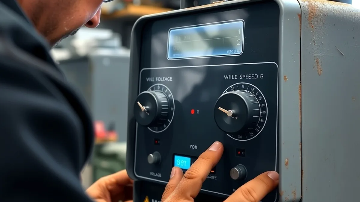
Think of the two dials as controlling two different physical questions, and most settings confusion disappears. Wire feed speed answers “how much metal and how much current?” — the drive rolls push wire into the arc at a rate measured in inches per minute, and because that wire is the path current takes, the faster it feeds, the more amps the arc must draw to melt it off at the point of contact. This is the counterintuitive heart of constant-voltage welding: you do not set amperage directly, you set it indirectly by choosing how fast to feed cold wire into a puddle that has no choice but to melt it. Push the wire faster and the machine answers with more current. That is why flux core amperage charts are essentially wire-speed charts in disguise, and why every professional habit of “setting the heat” in wire welding actually begins with the wire feed knob rather than the voltage knob.
Voltage answers a different question: “how far does the arc reach and how fluid is the puddle?” Voltage sets the length of the arc between the wire tip and the workpiece, and arc length directly controls the width of the heat zone, the wetting behavior at the toes, and the overall profile of the finished bead. Crank voltage up and the arc lengthens, the puddle widens and flattens, and the toes wash into the plate — until the arc goes unfocused, spatter climbs, and undercut appears at both edges. Drop it too far and the arc short-circuits constantly, the wire stubs and stabs, and you get a tall, ropey bead with cold, rolled-under toes that never fused. Full pairings are in the wire speed and voltage chart, and this parameters guide explains how the two trade off.
The reason they feel coupled is that they are, and this is where most dial-chasing goes wrong. If you increase wire speed without increasing voltage, you are feeding more metal into an arc that is too short to melt it at the rate you are demanding, so the wire pushes into the puddle and stubs — the arc stutters, the machine bangs, and the bead gets colder even though you added current. Raise voltage without wire speed and you lengthen an arc that is melting a thin trickle of wire — a very hot, wide, shallow bead that spreads energy instead of concentrating it. The two dials have to move as a ratio: pick your amperage from wire feed speed using thickness, then adjust voltage until the bead is flat to slightly convex with toes washed into the plate. Sound is the checkpoint — a soft hiss with a wide agitated puddle means too much voltage, a harsh crackle with stubbing means too little, and a steady low frying sizzle means you are there.
It helps to understand why flux core behaves a little differently from solid MIG wire here, because the tubular electrode changes the balance. The wire is a thin steel tube packed with powdered flux, so it has less metal per inch than solid wire, melts over a longer stickout, and needs less current per inch of feed. That is why flux core runs more voltage relative to amperage than you would expect from MIG — too short an arc smothers the flux reaction before it can shield the puddle — and why effective current runs higher than your dial suggests. Electrode and arc theory is covered in what is flux core welding.
Polarity: The Setting That Comes Before All the Others
Before you touch a single dial, confirm which way the electrons are flowing, because polarity is the settings decision that silently invalidates every other setting you make. In a wire feed welder, current has to travel from the machine, through the gun cable, into the wire at the contact tip, across the arc, and back through the workpiece — and you choose which end of that loop is positive. Self-shielded flux core, the gasless wire that ships in nearly every hobby machine, runs DCEP: direct current electrode positive, also called reverse polarity, where the wire is the positive terminal. This is not a preference or a tradition; the flux chemistry in those wires is formulated around that heat distribution, and the shielding gas they generate only forms correctly under it.
The consequence of getting it wrong is severe and misleading. On electrode negative, roughly two-thirds of the arc heat lands in the workpiece instead of at the wire, so the tubular electrode cannot melt off at the rate the drive rolls are feeding it. The wire buckles, the arc wanders across the plate looking for a stable path, spatter becomes explosive and popcorn-like, and the bead sitting on the plate is wide, shallow, and cold with no penetration — while still producing smoke and slag, which is what makes wrong polarity so deceptive. It looks like flux core welding while failing at every part of it. You can chase voltage across its entire range and never fix it, because the problem is heat location rather than heat quantity. The full explanation of why the split falls where it does is in the polarity guide, which also covers changing polarity on terminal-post machines versus front-panel switches.
Gas-shielded flux core and solid MIG wire flip the requirement: they run electrode negative, DCEN, because with external shielding gas handling arc protection, the process wants more heat driven into the base metal and a gentler melting of the solid or tubular electrode. Since many modern machines are multi-process, this means the polarity switch is something you must consciously revisit every time you change wire type. The spool label is the authority — every reputable wire prints its required polarity on the box — and if a session felt right while the weld stayed wrong, polarity is the first suspect. A machine can have calibrated dials, correct stickout, clean metal, and a skilled operator and still produce garbage because of a rocker switch in the wrong position. Verify it with a test bead before you trust any chart here.
Stickout: The Hidden Variable That Moves Your Amps
Stickout — properly called contact-tip-to-work distance, or CTWD — is the distance between the end of the contact tip and the surface you are welding, and it is the one settings variable you control with your hands instead of a dial. In MIG welding the standard is about 1/4 inch, but self-shielded flux core wants considerably more, typically 1/2 to 3/4 inch, and some industrial wires are specified out to a full inch. That is not a stylistic quirk. The longer stickout serves the flux: the wire is being preheated by resistive I²R heating as current passes through that length of steel before it ever reaches the arc, which helps the tubular sheath and its flux powder begin breaking down on schedule, and the extra distance keeps the contact tip out of the spatter plume that gasless wire throws far more violently than solid wire.
What that resistive heating does to your settings is the important part, and almost nobody accounts for it. Every additional eighth of an inch of stickout raises the effective current at the arc, because you are adding resistance in series with a moving conductor and the energy lost in that resistance turns into heat in the wire itself. Going from a 1/2-inch stickout to a 1-inch stickout can easily add 20 to 30 amps of effective current on 0.035 wire — a change as large as several clicks of your wire speed dial. This means two welders who set identical dials can produce completely different welds if one of them holds the gun a half inch further back, and it also means that as you work through a long joint and your stickout drifts, your settings are drifting with it even though your hands never touched a knob.
The other half of stickout’s effect is arc focus, and it works against the amperage gain. A longer stickout makes the arc softer and less directed, spreading heat over a wider area rather than concentrating it into the joint root. A drifting long stickout therefore gives you more total current and less penetration — a combination that produces a bead looking hot but sitting on the plate. Too short is its own problem: the tip ends up inside the arc zone, overheats, burns back, and welds the wire to it, while reduced resistive heating leaves you below the chart’s current. Set stickout consciously at 3/4 inch, hold the gun angle steady as you travel, and trim the wire fresh after every arc stop. When your weld changes character halfway through a job, check stickout before the dials — troubleshooting guides list it among the most frequently missed causes.
Settings by Material Thickness: The Master Chart (16 Gauge Through 1/2 Inch and Beyond)
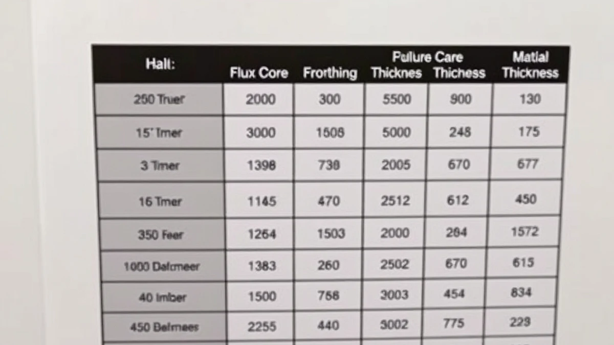
Here is the table people actually come for, and the honest caveat that should come with every settings chart ever published: these are starting points, not destinations. The numbers below assume self-shielded flux core wire at 0.035 inch, correct DCEP polarity, a 3/4-inch stickout, clean mill-scale-free steel, flat position, and a machine with enough output to actually reach them. Change any of those assumptions and the correct numbers move, which is why two charts on the internet can disagree by three volts and both be right for the conditions they were written under. Treat the ranges as the middle of your machine’s window, run a test bead, and adjust from there. Current rises roughly with thickness, and a useful rule of thumb for flux core is 0.8 to 1.0 amp per thousandth of material per pass. The full relationship is in the flux core amperage chart.
| Material thickness |
Voltage range |
Wire speed (ipm) |
Approx. amps |
Practical notes |
| 16 ga (0.060″) |
17.5 – 19.0 V |
100 – 130 |
60 – 80 A |
Small 110V machine territory. 0.030 wire often friendlier. Watch for burn-through on butt joints; tack and stitch. |
| 14 ga (0.075″) |
18.0 – 19.5 V |
130 – 165 |
80 – 100 A |
Upper end of any 90–110 amp continuous machine. Short beads, let it cool between passes. |
| 11 ga (0.120″) |
19.5 – 21.0 V |
175 – 215 |
105 – 130 A |
The sweet spot for a 140-amp class welder. Fillet welds at 1/4″ leg with no trouble. |
| 1/8″ (0.125″) |
20.0 – 21.5 V |
185 – 225 |
110 – 135 A |
Single pass full penetration on butt joints needs a 1/16″ root gap or a 60° bevel. |
| 3/16″ (0.187″) |
21.5 – 23.0 V |
255 – 305 |
155 – 185 A |
Where most 110V machines hit their ceiling. On a welder that only truly makes 100 A, run two passes. |
| 1/4″ (0.250″) |
23.0 – 24.5 V |
320 – 385 |
190 – 230 A |
Effectively requires 230V input or a very strong inverter. Bevel edges for full penetration. |
| 5/16″ (0.312″) |
24.0 – 25.5 V |
390 – 455 |
235 – 275 A |
Multiple passes. Interpass temperature under 400°F for structural work. |
| 3/8″ (0.375″) |
25.0 – 26.5 V |
460 – 540 |
275 – 325 A |
Industrial 230V/30A machine. Stringer beads, stagger passes, clean slag between each. |
| 1/2″ (0.500″) |
26.5 – 28.0 V |
525 – 600 |
315 – 360 A |
Outside the reach of every 110V machine made. Single-V groove, 4–6 passes, preheat if cold. |
| 5/8″ and heavier |
27.5 – 29.0 V |
625 – 725 |
375 – 435 A |
Dedicated industrial power source, qualified procedures, and preheat/interpass control. |
Read down the amps column and you will notice the machine-capability boundaries falling out naturally, which is the most useful thing a chart can do for you. Anything at or below roughly 130 amps is within reach of an honest 110-volt machine; the 155-to-185 range sits at the edge of a 140-amp box and will drive it into thermal protection quickly. Everything from 1/4-inch up assumes 240-volt input, which is where input power stops being theoretical. Whether your machine can credibly do the job is covered in the parameters overview, while budget flux core welders and 110V flux core machines show what each price class really delivers.
Two details in the table deserve emphasis because they are the ones beginners skip. First, thickness alone does not determine settings — joint geometry does. A 1/4-inch plate welded as a lap joint with an open edge behaves more like a thinner section at the edge, where heat concentrates, than like a solid 1/4-inch block, and the same plate welded as a closed butt joint with a root gap behaves like a thicker one because the heat has somewhere to go. Second, the ranges are wide because travel speed is itself a settings lever: push faster and you can run slightly hotter to hold fusion, slow down and you must take heat out to avoid washing out the edges. Welding sheet metal with flux core covers the thin-end adjustments, including the stitch-and-cool rhythm that keeps 16-gauge from blowing through.
Settings by Welding Position: Flat, Horizontal, Vertical-Up, and Overhead
Gravity is a settings input, and it is the one most often forgotten because it does not have a knob. A puddle that stays put when you are welding flat will sag, drip, and run when you rotate the same joint ninety degrees, because molten steel’s resistance to gravity is a function of its fluidity — and fluidity is controlled by heat. The entire logic of out-of-position settings is therefore one sentence long: reduce heat enough that the puddle freezes before it can move, without reducing it so far that you lose fusion at the toes. That balance is tighter out of position than flat, which is why the ranges below are percentages rather than absolutes — a 15 percent cut on a 150-ipm flat setting is 22 ipm, while the same percentage on 500 ipm is 75, and the two have very different consequences for penetration.
| Position |
Voltage vs. flat |
Wire speed vs. flat |
Why |
Watch for |
| Flat, 1F (downhand) |
Baseline |
Baseline |
Gravity helps the puddle wet and spread into the joint. |
Most forgiving position; widest settings window. |
| Horizontal, 2F |
+0.0 to +0.5 V |
−5% to −10% |
Keep enough heat to wet the top toe while slowing feed to stop the bottom toe sagging. |
Heavy top toe, thin bottom toe; overlap your pool into the previous ripple more. |
| Vertical-up, 3F |
−0.5 to −1.5 V |
−10% to −20% |
The puddle must solidify under the arc and act as a ledge for the next deposit. |
Sagging, saggy root, trapped slag if too hot; whip or weave only enough to tie the toes. |
| Overhead, 4F |
−1.0 to −2.0 V |
−15% to −25% |
Minimal fluidity — a puddle with any real flow will drip onto you. |
Bead too small or cold-looking is normal and acceptable overhead; do not chase flat aesthetics. |
| Vertical-down |
−0.5 to −1.0 V |
−5% to −15% |
Fast travel with less heat; the puddle never gets a chance to build. |
Thin material only. Poor penetration on anything above 1/4″. Rarely correct for flux core structural work. |
Vertical-up deserves its own paragraph because it is the position where settings discipline matters most and where the wrong starting numbers cause the most frustration. When you weld uphill, each new deposit lands on a solidified ledge rather than into an open trough, and the puddle you are adding to is still partially molten from the previous one. If your heat is at flat settings, that ledge never fully forms — the pool stays liquid longer than your travel speed can outrun, and it slumps into a bulging, irregular bead with slag trapped underneath. Reducing wire speed by 10 to 20 percent and taking about a volt out lets the leading edge freeze while you are still on top of it, producing the stacked-dime appearance that is really a record of solidification at the right rate. Vertical-up flux core settings gives the numbers, the horizontal settings guide covers 2F, and vertical welding techniques addresses how much to weave.
Joint Type Adjustments: Butt, Fillet, Lap, and Open Root
Two plates of identical thickness can demand genuinely different settings depending on how they are arranged, and this is the second half of reading a chart correctly. Heat spreads along whatever metal is attached, so a plate lying on a steel table runs colder than the same plate held free, a T-joint doubles the material at the root, and a lap joint concentrates heat at the exposed edge. Getting this wrong is one of the classic settings mistakes, and it is invisible if you only ever think in terms of thickness.
Butt joints want the reference settings from the chart, adjusted for fit-up. A tight fit-up with no gap behaves as drawn — full thickness, heat spreading laterally, single pass up to about 1/8 inch and multiple passes above that. A butt joint with a root gap opens the arc into the gap and lets heat escape downward, so it effectively needs more current than the thickness suggests: add 5 to 10 percent wire speed and roughly half a volt to compensate for the gap, exactly as you would when welding a full-penetration groove weld. Beveled edges reduce the required current per pass because each pass fills less volume but must still penetrate the root, so run the lower end of the voltage range to keep the arc focused rather than spreading heat across the bevel walls.
Fillet welds in T and corner joints are where voltage adjustments earn their keep, because the puddle has to wash up a vertical face while simultaneously wetting the horizontal one. Too little voltage and you get a bead that sits in the corner with a cold, rolled edge on the vertical side — it looks fused but a cut-and-etch will show the fusion line stopping short. Too much and gravity pulls the top half down while the bottom toe undercuts. The fix for the common asymmetry is a small work-angle change plus a touch of voltage: keep the gun bisecting the joint at 45 degrees and add half a volt over your butt-joint baseline to help the puddle climb the vertical wall. Above 1/4-inch leg size, plan on stringer beads rather than wide weaves — a wide weave traps slag in the center.
Lap joints need the opposite treatment. The top plate’s exposed edge is a thin fin that heats far faster than the plate beneath it, so full chart settings melt the edge back while the bottom plate stays barely tacked. Drop half a volt and 5 to 10 percent wire speed, bias the arc toward the bottom plate, and let the puddle wash up onto the thin edge instead of attacking it. Open-root and pipe joints are different again: with no backing and a visible gap, excess heat drops the root through into the bore. Reduce voltage slightly below chart value, keep wire speed at or just above it so the wire keeps pushing into the gap, and use a tight, fast weave that freezes quickly. The skills — travel speed, gun angle, puddle placement — are in flux cored arc welding techniques.
Wire Diameter: How .030 and .035 Change Your Settings
Wire diameter is a settings decision, not a shopping decision, because swapping from 0.030 to 0.035 on the same machine and the same plate changes every number you were about to use. The reason is simple geometry: a 0.035-inch wire has roughly 36 percent more cross-sectional area than a 0.030-inch wire, so at any given amperage it melts off more slowly — which means to hold the same current you must feed the thinner wire substantially faster. In practice, most published charts show the thinner wire needing 25 to 40 percent higher inches-per-minute for the same amps, which gives 0.030 about 0.44 amps per ipm against 0.035’s roughly 0.60. Set both wires to the same dial position and you are running two different welds.
| Factor |
0.030″ (0.8 mm) wire |
0.035″ (0.9 mm) wire |
| Current per unit feed rate |
~0.44 A per ipm |
~0.60 A per ipm |
| Feed rate for ~100 A |
225 – 240 ipm |
160 – 180 ipm |
| Best material range |
20 ga – 3/16″ |
14 ga – 1/2″ |
| Voltage for 1/8″ plate |
19.5 – 21.0 V |
20.0 – 21.5 V |
| Low-end machine behavior |
Easier to reach thin-sheet amps on small 110V machines |
Harder to slow down enough for 20 ga without burn-through |
| High-end behavior |
Runs out of deposition above ~3/16″; needs more passes |
Carries heavier sections in fewer passes; needs more machine output |
| Stickout sensitivity |
Higher — small changes shift amps noticeably |
Lower — more forgiving of gun-position drift |
The practical guidance falls out of that table quickly. If your machine is a small 110-volt box that only makes 90 to 120 amps honestly, 0.030 is the right default for anything under 1/8 inch because you can actually reach the low end of the wire’s useful range. If your machine makes 180 amps on 240 volts and you regularly weld 3/16 and up, 0.035 gives you the deposition you need without four-pass sequences on quarter-inch plate. Running 0.035 on a small machine at maximum settings is legitimate but pushes the box straight to its thermal limit, while running 0.030 on heavy plate is simply inefficient — many passes, each reheating the last and widening the heat-affected zone. Deeper comparisons live in 0.030 versus 0.035 flux core wire, with selection covered by best flux core wire and flux core wire types.
One often-overlooked mechanical consequence: wire diameter changes drive roll groove requirements and liner wear behavior. Loading 0.030 wire into a machine whose rolls are grooved for 0.035 produces slippage that feeds 10 to 20 percent less wire than the dial commands, and the result is a bead that runs colder than every chart says it should — a settings problem with a mechanical cause that will send you chasing voltage for an hour. Swap the rolls whenever you swap diameter, set the tension for the smaller wire, and verify actual feed rate by marking six inches of wire and timing the gun. Drive rolls for flux core wire walks through groove numbering, knurl patterns, and the tension test.
Gasless Versus Gas-Shielded: Why the Settings Are Not Interchangeable
The words “flux core settings” cover two materially different processes, and treating their numbers as interchangeable is one of the more reliable ways to produce a bad weld with a correct-looking chart. Self-shielded flux core — FCAW-S, the gasless wire — carries its own shielding in the tubular electrode and runs on DCEP, needs a longer stickout, generally wants a drag technique, produces heavy slag, and deposits a weld that is tougher and more penetration-hungry but visually rougher. Gas-shielded flux core — FCAW-G — uses an external gas bottle, almost always 100 percent CO2 or a CO2-rich mix, runs on DCEN for the vast majority of wires, wants a shorter stickout around 1/2 inch, and behaves much more like a fast, clean MIG process with higher deposition rates and far less slag. The arc characteristics are different enough that the correct voltage for one is visibly wrong for the other on the same plate.
Concretely, the differences break down like this. Gasless wire wants slightly more voltage relative to current, because the arc must stay long enough for the flux reaction to generate shielding — choke it short and you starve the shield and invite porosity. Gas-shielded flux core puts more heat into the base metal per amp because of the polarity difference, so you usually drop a few percent wire feed for the same thickness and gain noticeably deeper fusion. Travel speed differs too: FCAW-G rewards faster travel, while self-shielded wire needs a slower crawl so the shield can establish. Push versus pull flips as well — gasless is almost always dragged, while gas-shielded can be pushed flat and horizontal, which is why the push-or-pull question has no single answer.
And then there is plain MIG with solid wire, which is really a third set of settings that people lump in by mistake: solid wire with 75/25 argon-CO2 wants DCEN, a 1/4-inch stickout, a push in flat positions, roughly 10 to 15 percent less voltage than gasless flux core at the same thickness for a comparable bead, and it produces almost no slag and much less spatter when set correctly. On a multi-process machine you are juggling three charts depending on what you load. Flux core versus MIG compared, flux core versus solid wire, and gas MIG versus flux core map different slices of that territory, while gasless flux core wire welding covers the self-shielded setup alone. For where the process sits overall, what is flux core welding and stick versus flux core explain why you would choose one before touching a dial.
Extension Cords and Input Power: Settings Your Dials Cannot Fix
Every settings chart in this article assumes the machine is receiving the voltage it was designed to receive, and in a home shop that assumption is often quietly false. A welder running on 120 volts at full output can draw 17 to 20 amps of line current, and feeding that through a hundred feet of 16-gauge extension cord — the orange one, the one everyone owns — introduces real resistance into the circuit. Copper at 16 gauge runs about 4 ohms per thousand feet, so a hundred-foot cord is a two-hundred-foot round trip of roughly 0.8 ohms, and at 18 amps that is close to 14 volts of drop. Your machine sees 106 volts instead of 120. It answers with a weaker arc that sags under load, trips its own low-voltage protection, or thermally protects early — and since nothing on the front panel says input voltage low, the symptom looks exactly like a settings problem: a bead that will not get hot no matter where you put the dials.
The fixes are physical rather than editorial. Use a welder-rated cord, not an appliance extension — 10 gauge for up to 25 feet on a 140-amp class machine, 8 gauge for 50 feet, 6 gauge beyond; the math is unforgiving, and wire gauge for 30-amp 220V circuits shows the same calculation on the 240-volt side. Better still, plug into a dedicated outlet near the work and move the machine rather than extending the cord. Utility power varies too: a machine rated on 120-volt nominal supply behaves differently at the end of a long rural feeder, which is why your cousin’s numbers do not work in your shop.
Generators deserve their own warning because they amplify all of this. A welder is a hostile load for a generator — high current, near-unity power factor, sharp transient demand at arc start — and a unit sized at the machine’s rated output will often stall, hertz-droop, or produce arc instability the moment you strike. Run a generator with real headroom — ideally 1.5 to 2 times the welder’s rated input — and expect the settings window to shrink accordingly; sizing a generator for a 140-amp welder and will a 5000-watt generator run a welder work the arithmetic. Manufacturers publish their own supply guidance: Miller’s resource library and Lincoln Electric’s technical library both carry installation guides covering wire size, breaker sizing, and allowable voltage drop. Fix the supply first, then judge the puddle.
How to Dial In: The Test Bead Method
Charts get you close; test beads get you right. The method below takes about fifteen minutes the first time and five minutes every time after, and it replaces guessing with evidence. Start by cutting two or three inches off the wire so your stickout is fresh, clamping the ground directly to the workpiece rather than to the table or the part’s far end, and setting polarity to DCEP. Choose the mid-range values from the thickness table — say 22 volts and 280 ipm for 3/16-inch plate — and write them down. Strike an arc on a scrap piece of the same thickness and same joint geometry as your real work, and run two to three inches at a steady travel speed you could comfortably repeat. Then stop, let it cool, chip the slag, wire-brush it, and look at what you have.
Read the bead against four criteria. Width should be roughly one and a half to two times the plate thickness for a single pass — much wider means excess voltage, much narrower means not enough. Reinforcement should sit 1/32 to 1/16 inch proud of the surface; a tall roped bead means the puddle never spread, which is a voltage deficit. Toe fusion is the one that matters structurally: both edges should wash smoothly into the plate with no visible lip or shadow line. If a toe sits on top of the metal like a bead of caulk, you are cold, and the fix is more wire feed first. Spatter should be fine and sparse; heavy globular spatter with a harsh crackle points at too little voltage relative to feed rate. Cross-section testing — cutting, polishing, and etching the bead to see actual penetration — is the definitive version of this check and the standard the industry uses to qualify a procedure, as TWI describes it.
Then adjust, but adjust one dial at a time and in small increments, because the whole point of the method is to isolate cause from effect. If the bead was cold and unpenetrated, raise wire speed one or two increments and run another bead — heat first. If the heat was right but the profile was too narrow and ropey, leave wire feed alone and raise voltage half a volt — shape second. If you fixed the profile and it now looks too wide or is undercutting, you have overshot voltage, so come back down rather than also touching the wire feed. Three or four beads will converge on a stable pair of numbers — write them on the machine. The deliberate practice side of that loop is covered in practicing welding at home, with gun handling in mastering the wire feed welder.
Symptom-Based Tuning: What the Bead Is Telling You to Turn
Once the test-bead loop is familiar, you can work in the other direction: read a finished weld and know which dial to reach for. This is the skill that separates a welder who understands settings from one who owns a chart, because in the field you rarely get to run a controlled experiment — you get a bead that looks wrong and a job that needs finishing. The table below maps what you will actually see to its likely settings cause and the specific correction, in the order to apply it. Several symptoms share causes — cold lap, trapped slag, and lack of fusion are all downstream of insufficient heat — and porosity has settings causes but is more often contamination, shielding loss, or a bad stickout.
| Symptom you see |
Most likely cause |
Turn this dial |
Direction and amount |
| Wide, flat, washed-out bead with undercut at both toes |
Excess voltage for the thickness |
Voltage, then wire speed |
−0.5 to −1.0 V; if bead is still too large, −5% wire feed |
| Spatter-heavy arc with a harsh, rapid crackle and visible wire stubbing |
Feed rate too high for the arc length |
Wire feed first, then voltage |
−5 to −10% ipm; if the arc gets short and choppy, +0.5 V |
| Bead sits proud and ropey, both toes visibly un-fused |
Insufficient current or voltage |
Wire feed first, then voltage |
+5 to +10% ipm; then +0.5 V if the profile stays tall |
| Cold lap — filler piled against the plate with a shadow line at the toe |
Too cold overall, or travel too fast |
Wire feed |
+5 to +10% ipm; slow travel slightly before touching voltage |
| Burn-through holes on thin material |
Too much heat concentrated in one spot |
Voltage and wire feed together |
−0.5 to −1.0 V and −5 to −10% ipm; add stitch pauses |
| Wire melts back and welds itself to the contact tip |
Short stickout, low feed, or long arc dwell in one place |
Stickout, then wire feed |
Restore 3/4″ CTWD; +5% ipm; keep moving |
| Wire buckles or feeds erratically before the arc |
Mechanical, not electrical — rolls, tension, liner, or kinked spool |
None — check hardware |
Verify roll groove, re-set tension, clean liner, confirm polarity |
| Slag will not lift, or lifts with chunks of metal attached |
Too cold, too slow, or excessive weaving |
Wire feed, then travel speed |
+5% ipm; increase travel speed; use stringers over wide weaves |
| Porosity or pinholes under the slag |
Contamination, lost shielding, damp wire, or too long a stickout |
Not a dial — check conditions |
Clean joint, shorten to 3/4″, dry storage, check wind, verify gas if FCAW-G |
| Arc wanders or pulses without settling |
Wrong polarity, bad ground, or input voltage sag |
Polarity, ground, supply |
Confirm DCEP, clamp to clean metal near the joint, check cord and outlet |
| Good bead for 4 inches, then arc weakens and machine fans roar |
Duty cycle reached — machine is thermally limiting |
Neither — manage duty cycle |
Pause 2–4 minutes, improve ventilation, or reduce settings one step |
| Bead looks right but cracks after cooling |
Technique or metallurgy, not settings — hydrogen, restraint, or cold base metal |
Stop adjusting |
Preheat if thick or cold, slow cooling, check wire certification |
Two of those rows deserve expansion because they are the ones that send people into pointless dial-chasing. Erratic feeding is almost never a settings problem — a bent liner, a groove-wrong drive roll, or tension cranked so tight it shaves the wire will imitate every electrical symptom in the table while the dials sit untouched. And porosity is a condition problem before it is a settings problem: porosity in welding walks through the full diagnostic order — gas, cleanliness, wire condition, wind, stickout — before you are allowed to blame voltage. Flux core welding troubleshooting covers the same ground with photographs, Work the diagnostic order in flux core welding troubleshooting and porosity in welding — gas, cleanliness, wire condition, wind, stickout — before you blame voltage. Ventilation belongs in the settings conversation too: OSHA’s welding, cutting, and brazing standards and NIOSH’s welding health topic explain why.
Common Settings Mistakes (and What They Cost You)
The same handful of errors account for most bad flux core welds blamed on skill. Setting from the machine’s door sticker instead of a real chart is first: those plates are generic, frequently written for solid wire with gas, and almost never account for position or joint type. Changing two dials at once is second, and it is fatal to learning, because when two variables move together you cannot attribute the improvement — you end up with a good bead you cannot reproduce and a bad one you cannot diagnose. Treating the amps label as a setting is third: “my welder is a 140” is a duty-cycle claim, not a position on a dial, and welding as though you have 140 amps continuous when you really have 100 produces over-large beads, blown edges, and an overheating machine.
Then come the quieter ones. Ignoring stickout drift across a long joint silently changes your effective current by tens of amps. Carrying flat settings into vertical or overhead guarantees sag and trapped slag, because the heat that was correct for downhand work will not freeze in time when gravity is working against you. Chasing settings when the real fault is mechanical or electrical — wrong polarity, a slipping drive roll, a dirty ground, a sagging supply — wastes an afternoon and teaches you the wrong lesson. And copying someone else’s numbers without verifying them on your own machine ignores that dial calibrations differ by twenty percent or more between two machines of the same model. Each of these is covered in the mistakes guide, and they compound — three stacked together is what turns a twenty-minute repair into a weekend of grinding.
Machine-Specific Quirks: Cheap 110V Boxes Versus Industrial Machines
A $180 110-volt flux core welder and a $3,000 industrial machine are not the same tool with different price tags; they are different instruments that happen to make arcs, and they respond to settings work in genuinely different ways. The budget class — small transformers and entry-level inverters — typically gives you a voltage knob numbered one through ten with no calibration, a wire speed knob marked only with an arrow, an effective window of roughly four dial positions, and a rated output that is true for ninety seconds out of ten minutes. Their duty cycles are the real constraint: a machine sold as 140 amps frequently delivers 100 to 110 amps continuously, which puts the top third of the thickness table out of reach no matter where the dials sit.
Industrial machines invert almost every one of those assumptions. Real units on the display, not positions on a scale. Duty cycle ratings that hold at rated output at 40°C ambient, tested to published standards rather than marketing ones. Synergic control, where one knob sets wire feed speed and the machine selects voltage from a stored curve for that wire diameter — you stop tuning two variables and start telling the machine what you are feeding it. Add run-back to prevent crater cracks, spot timers for repeatable tacks, better arc starting, and thermal headroom that lets you weld continuously through the range the sticker promises. A chart therefore means something literal on an industrial machine and something approximate on a hobby one: the row lands on the first, while the second needs a test-bead pass to find its center.
Budget machines also have specific, predictable quirks worth knowing before you blame your technique. Many have fans that run constantly and never help duty cycle when you stop. Some sag visibly under load — strike the arc and the display drops, which is the machine telling you the supply is thin. Others have non-linear wire speed controls, so the gap between positions 3 and 4 is not the same as between 7 and 8. Knowing your machine’s personality — where its real window sits, how long it runs before thermal cutout, how much it sags on your circuit — is worth more than any chart, and that is what the test-bead method discovers. Understanding flux core power output explains the ratings, and a real 90-amp machine review shows how far a small welder is pushed when the settings are right.
Frequently Asked Questions
What are good starting settings for flux core on 1/4-inch steel?
Start at 23.5 volts and 350 inches per minute with 0.035 wire on DCEP, a 3/4-inch stickout, and flat position — that sits mid-range in the thickness chart and gives you room to move either direction. Run a three-inch test bead, then tune: if the bead sits proud and narrow, raise wire feed in 10-ipm steps; if it washes wide or undercuts the toes, drop voltage in half-volt steps. Expect around 190 to 230 amps at the correct setting, and expect a 110-volt machine to struggle — 1/4-inch really wants 240-volt input.
What does the amps number printed on my welder actually mean?
It is the peak output under ideal conditions, not a setting you can dial in. What matters is the continuous rating at your duty cycle — a 140-amp machine at 20 percent duty gives you two minutes of welding per ten. Size your expectations to the continuous number, not the headline, and check increasing a welder’s duty cycle for ways to extend it.
Do I need different settings for flux core versus MIG on the same machine?
Yes, and different polarity too. Self-shielded flux core wants DCEP, a 1/2 to 3/4-inch stickout, a drag technique, and more voltage relative to current; solid MIG wire wants DCEN, a 1/4-inch stickout, a push in flat positions, and roughly 10 to 15 percent less voltage at the same thickness. Never carry numbers across wire types.
Why does my flux core weld look cold even at maximum settings?
Because the fault is usually not heat quantity. Check polarity first — wrong polarity makes everything feel cold regardless of dial position. Then stickout, ground clamp placement, input voltage sag from a long cord, and drive roll tension. Only after those are verified should you suspect the machine itself, since a small welder at its maximum may still only be producing 90 amps.
How do I convert a numbered dial into actual inches per minute?
Mark six inches of wire sticking out of the gun, pull the trigger with the gun pointed into a bucket, and time how long the machine takes to consume it. Six inches in three seconds is 120 ipm. Do it at several dial positions and you now have your own calibration table — a ten-minute exercise that makes every chart you read directly usable.
Does stickout really change my amps?
Meaningfully. The longer wire adds resistance that heats the electrode before it reaches the arc, so going from a 1/2-inch stickout to a full inch can add 20 to 30 amps on 0.035 wire. That is several dial clicks’ worth of current arriving through your hand position instead of your settings, which is why a drifting stickout makes correct numbers produce wrong welds.
What is the practical difference between settings for .030 and .035 wire?
The thinner wire needs about 25 to 40 percent more feed rate for the same amperage because it has less cross-section to melt. So 100 amps might be 170 ipm on 0.035 but 230 ipm on 0.030. Voltage stays close — usually within half a volt for the same thickness — and 0.030 is the friendlier choice on small 110V machines welding under 1/8 inch.
Do I need different settings when welding outdoors?
Slightly, and technique more than dials. Self-shielded flux core tolerates wind far better than gas-shielded processes because its shielding is generated at the arc, but strong drafts still disrupt the envelope and cause porosity. If you see porosity in a breeze, shield the area before touching the voltage — and remember that wind is only one of several porosity causes. Protect yourself while you work: OSHA’s welding requirements cover ventilation and fume control.
Can I weld 1/2-inch plate with a 140-amp 110V machine?
Not in a single pass, and not comfortably in any pass. Half-inch plate wants 315 to 360 amps, which is far beyond what a 120-volt household circuit can sustain — the input side physically cannot deliver it. You can bevel heavily, preheat, and stack many small passes on a machine running at its absolute ceiling, but the honest answer is that 1/2-inch requires 240-volt input. See breaker sizing for why the circuit is the limit.
How do I know when my settings are actually right?
The bead tells you. Correct settings produce a steady frying-sizzle arc sound, a puddle that stays fluid but does not boil, a finished weld roughly one and a half to two times the plate thickness wide and 1/32 to 1/16 inch proud, both toes washed flat into the plate, and fine sparse spatter that brushes off. When you can predict those four things before you strike the arc, you understand your machine rather than just operating it.
Conclusion: Turning the Dials Into Judgment
Ray’s napkin of settings is still tacked to his garage wall, and he keeps it there as a reminder rather than a reference. It records eleven numbers he guessed at and none that mattered, and it sits a few feet from the sticky note that came with the welder — the one that said “1/4 plate: 4 and 6,” which turned out to be close to right for somebody else’s machine, somebody else’s circuit, and somebody else’s stickout. The lesson he took from that weekend was not that he needed better charts. It was that settings are a system: polarity decides where the heat goes, wire feed decides how much there is, voltage decides how the puddle behaves, stickout decides what actually reaches the arc, position and joint geometry decide how much you can hold, and the supply behind the machine decides whether the dials are telling you the truth.
That is why the method in this guide runs in a specific order: verify polarity, set stickout, check the ground and the power, pick the mid-range numbers for your thickness and adjust them for position, wire diameter, and joint type, then run a test bead. Read width, reinforcement, toe fusion, and spatter, move exactly one dial, and repeat. Three or four iterations and you will have numbers that belong to your machine on your circuit with your wire — because you can read a puddle rather than hunt for a chart. From there the craft opens quickly: joint technique and travel control, welding safety practices, and Britannica’s history of arc welding, which traces the process to the carbon arcs of the 1800s. What changes is whether the person holding the gun knows what each turn of the dial is doing.