The fence gate had been hanging crooked for two years, dragged down by rust and a failed hinge that some previous owner had “fixed” with what appeared to be a glob of metal applied during an earthquake. Priya had bought a compact wire feed welder six months earlier — it sat in its cardboard box in the garage, unopened, because every time she thought about using it, a mental movie played: the loud noise, the bright light, the sneaking suspicion that she’d somehow destroy the driveway, the gate, or herself. Welders, in her mind, were people born with a skill she didn’t have.
Then a friend came over, watched her struggle with a wrench and two mismatched bolts, and said the five words that changed the project: “Just weld the bracket back.” Twenty minutes later — after one session of settings fiddling, one abandoned first attempt that looked like caterpillar vomit, and one surprisingly clean bead — the hinge bracket was fused solidly to the post, and Priya was staring at her own weld with the slightly stunned expression of someone who had just discovered that the thing she feared was actually a procedure. Not a talent. A procedure. Steps in order, each one learnable, each one repeatable.
That discovery is what this guide is about. If you own a flux core MIG welder — or you’re about to buy one and want to know what you’re actually getting into — we’re going to walk the entire path from opening the box to inspecting a finished weld, with no skipped steps and no assumed knowledge. By the end, you’ll understand your machine, your settings, your technique, and your next move. The gate will still be waiting. It’ll just be waiting for someone who knows what she’s doing.
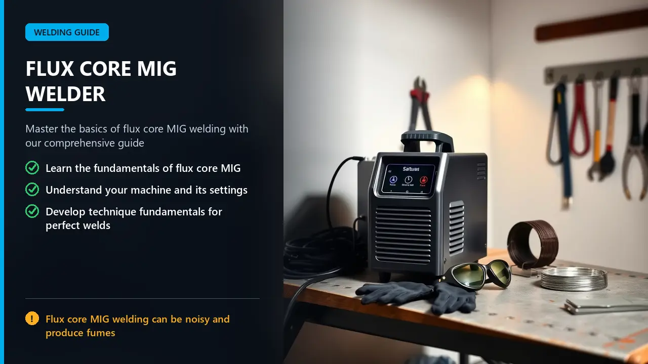
Key Takeaways: What You’ll Master in This Guide
Flux core welding is the most accessible arc welding process available to beginners — that’s not marketing, it’s geometry: the consumable carries its own shielding, the machines are affordable, and the process forgives the imperfect conditions (wind, light rust, outdoor work) that frustrate gas-shielded welders. Here’s the condensed roadmap:
- Know what your machine actually is. A “flux core MIG welder” is a wire feed welder running on DC electrode positive (DCEP) polarity with self-shielded flux core wire — no gas bottle involved. Getting polarity right is step zero. Our polarity guide explains why it matters.
- Setup determines your ceiling; technique determines where you land under it. Wire size, drive roll tension, contact tip condition, and clean base metal come before any discussion of gun angle or travel speed.
- Settings are a sound-and-sight skill. A good flux core arc has a steady frying sound and produces a slightly convex bead with even ripples. Learn to tune by ear using our settings guide.
- Drag, don’t push. Self-shielded flux core is pulled at a 10–15° trail angle — pushing blows your own shielding away from the puddle. Details in our push or pull guide.
- Clean, clamp, then weld. Surface prep and joint fit-up decide more about weld quality than any technique you’ll learn in your first month.
- Diagnose instead of guessing. Porosity, spatter, cold beads, and inconsistency each map to specific fixes — our troubleshooting playbook covers all of them.
- Safety isn’t a chapter — it’s a habit. Helmet, jacket, gloves, ventilation or respirator, fire watch: every session, no exceptions. See OSHA’s welding standards.
Now let’s open that box properly.
What a Flux Core MIG Welder Actually Is (Terminology, Sorted Out)
The naming confuses everyone at the start, so let’s clear it up in one pass — because understanding the label prevents expensive mistakes later.
A wire feed welder (technically a constant-voltage power source feeding consumable wire) is the machine category. Within that category, you can weld two main ways with wire: MIG (GMAW), which feeds solid wire and shields the arc with gas from a cylinder, and flux core (FCAW), which feeds tubular wire packed with flux that generates its own shielding. Many modern home-shop machines are multi-process — capable of both — which is why the market language gets slippery: a “flux core MIG welder” usually means “a wire feed machine set up to run flux core wire,” and often means “a multi-process machine that can also run MIG with gas.”
The functional difference at the machine level comes down to polarity. Self-shielded flux core wire requires DC electrode positive — the torch lead connects to positive, putting more heat into the consumable wire so it heats quickly enough to activate the flux chemistry. Solid-wire MIG runs the opposite — DC electrode negative (often labeled “reverse” on machine faceplates, which is a naming trap all its own). Flip the polarity wrongly and the arc becomes unstable, penetration collapses, and spatter multiplies — a mistake that looks exactly like having a defective machine. Our feature on flux core polarity settings walks through the cables, the machine labels, and the diagnostic signs of getting it backwards.
The shielding difference is the second pillar. MIG’s gas blanket comes from a cylinder (typically 75/25 argon/CO₂ for steel) and must cover the puddle at all times; flux core’s blanket is generated by the wire’s core as it melts, which is why flux core works outdoors, in drafts, and in positions where shielding gas would wander away. That portability advantage is the process’s superpower — and understanding it helps you appreciate why our feature on gasless flux core welding treats outdoor capability as the headline benefit.
If you’re still absorbing fundamentals, start with our complete explainer on what flux core welding is, then compare processes with flux core vs MIG side by side and the broader flux core vs MIG deep dive. Buyers evaluating whether the category suits them at all should read our honest take on whether flux core welders are any good — short version: yes, within their lane, emphatically.
Choosing Your First Machine (If You Haven’t Yet)
You can complete this entire guide on an inexpensive machine — the category’s accessibility is real — but a few selection decisions dramatically affect your learning curve. Prioritize, in this order:
Feed system quality over brand hype. The drive roll assembly is where budget machines cut corners, and inconsistent wire feed sabotages technique learning more than any other single factor. Look for machines with metal (not plastic) drive roll housings, adjustable tension, and a smooth, quiet motor. Reviews organized around this exact criterion live in our guides to the best flux core welders for beginners and the best flux core welders under $300.
True duty cycle. Duty cycle — the percentage of a ten-minute period the machine can weld at rated output before thermal shutdown — determines your rhythm. A machine that overheats every three minutes forces stops that fragment your practice. Entry-level 110V units typically run 20–35% duty cycles at their higher settings, which is perfectly adequate for learning and light projects. Understanding the math helps you plan sessions: our explainer on increasing duty cycle covers ventilation, ambient temperature, and workload strategies. If your work will include heavier sections, the best 110V flux core welders and 220V options widen your window.
Amperage range. For beginner-to-intermediate steel work, a 110V machine in the 30–140A range handles sheet metal through 1/4″ plate with appropriate wire. A 220V dual-voltage machine extends capacity to heavier structural material and often delivers better arc quality at the extremes. If budget allows one machine only, dual voltage is the flexibility play.
Multi-process future-proofing. A machine that also runs gas MIG (and ideally stick) grows with you — today’s flux core learner becomes tomorrow’s gas MIG aluminum hobbyist. Our comparison of flux core machine capabilities and the field-tested settings chart for flux core MIG welders give you realistic expectations for what entry-level hardware delivers.
Safety Setup: The Five Minutes Before the First Spark
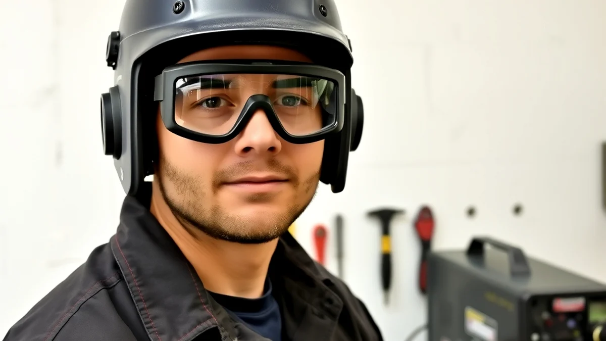
Every welding session begins the same way, and making the sequence automatic is one of the best habits you’ll build. Safety isn’t fear-based caution — it’s professional practice, and doing it properly is what lets you relax and focus on technique while the arc is lit.
Eye and face protection. A welding helmet with an appropriate shade — for flux core work, shade 10 to 13 depending on amperage — protects against arc eye (a genuinely painful corneal burn from UV exposure) and spatter. Auto-darkening helmets have become inexpensive enough that there’s little reason to start with a fixed-shade bucket, though fixed-shade forces you to learn the “nod” technique many veterans prefer. Whatever you wear, confirm the lens actually darkens before trusting it — dead batteries in an auto-darkening lens are a classic rookie failure, and our guides to testing auto-darkening helmets and whether they’re safe cover verification.
Clothing. Natural fibers only — cotton or leather. Synthetic fabrics (polyester, nylon, rayon) melt onto skin when spatter lands, turning a minor splash into a burn. Long sleeves, closed collar, leather gloves, over-the-ankle boots. Roll-up cuffs and sneakers are the two most common backyard injuries. Our welding safety tips overview covers the full checklist.
Breathing. Flux core generates more fume than solid-wire MIG — the flux itself produces smoke as it burns. In an open garage with the door up and a fan moving air, casual exposure is modest; in a closed shop, weld for minutes not hours without extraction. A P100 half-mask respirator is inexpensive insurance, and our best welding respirators review helps you pick one you’ll tolerate wearing. The health science — what’s in welding fume and why chronic exposure matters — is summarized honestly in our piece on whether welding fumes are toxic, with the regulatory baseline at OSHA and research context at NIOSH.
Fire prevention. Clear a ten-foot radius of paper, rags, solvents, and sawdust. Have a fire extinguisher within arm’s reach. Flux core throws incendiary spatter further than beginners expect — a single rolling BB into a dry leaf pile has ended many a first welding session with a garden hose. After finishing hot work, check the area behind and beneath your project; hidden embers smolder quietly.
Electrical and ergonomic. Inspect the ground clamp — a poor ground causes arc instability that mimics machine faults. Position your work so you’re not welding over your head on day one (work at comfortable heights while learning). Keep drinks away from the work area (metal containers only — a plastic bottle near your arc is a science experiment nobody wants).
Step One: Prepare the Workspace and the Metal
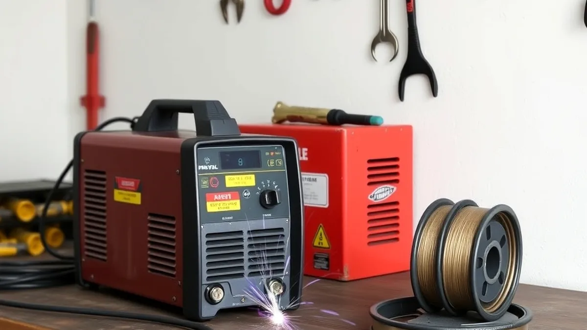
Walk into any professional shop and you’ll notice something odd: the experienced welders spend proportionally more time grinding, brushing, and clamping than the new ones. This isn’t personality — it’s priority. Joint preparation is the highest-leverage activity in welding, and it costs nothing but a few minutes.
Clean the joint area. Grind or wire-brush both pieces where the weld will land — remove mill scale if it’s heavy, rust, paint, and especially oil or cutting fluid. You don’t need mirror-bright steel everywhere (that’s perfectionism), but the weld zone itself should be clean, dry metal. Contaminants in the arc produce porosity — the pinholes that are the number-one defect of beginner welds — and our visual guide to porosity in welding shows exactly what contamination looks like frozen into a bead.
Special cases: galvanized steel needs the zinc coating ground off in the weld zone (zinc vaporizes into porosity and the classic metal fume fever flu-symptoms — our guide to welding galvanized steel with flux core covers safe handling). Painted metal needs the coating removed plus a margin for heat-affected-zone fumes. Oily recycled steel needs degreasing. When in doubt, clean more.
Fit and clamp. Position pieces precisely, then tack weld — small 1/2″ spot welds at corners and intervals — to lock geometry. Check alignment after tacks (tacking pulls metal; that’s physics, not error), adjust if needed, then proceed to full beads. Clamps are your third hand: two good clamps beat four hands any day, and a joint that moves mid-weld produces the wandering beads we’ll troubleshoot later. If your project involves joining dissimilar metals or an unusual configuration, research the specific joint first — welding aluminum to steel, for instance, is a different problem entirely than steel to steel.
Plan your weld sequence. Before striking an arc, decide: which side gets welded first, where you’ll start and stop, which segments will be out of position, and how many passes the joint needs. A minute of planning prevents the mid-project improvisation that produces stalled arcs, awkward reach positions, and warped assemblies. This sequencing mindset scales directly into our more advanced flux cored arc welding techniques guide — think of it as the same skill at a higher level.
Step Two: Set Up the Machine
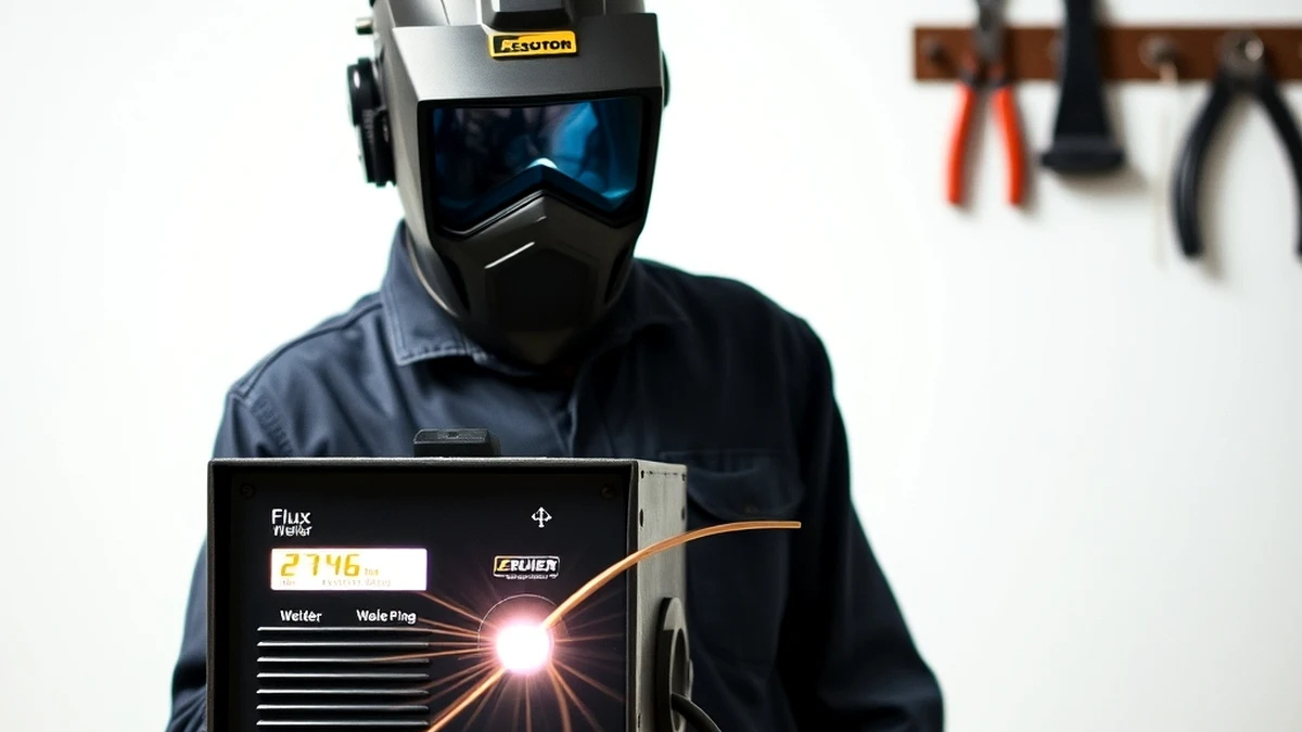
Machine setup follows a fixed sequence, and doing it in order prevents the classic “I did everything right except the thing that matters” failures.
1. Verify polarity (DCEP). For self-shielded flux core: the torch/stinger lead goes to positive (+), the ground clamp to negative (−). Many machines require moving a cable on the front panel; others switch electronically (check the manual — and if the manual is gone, trace the cables from the machine terminals). Wrong polarity gives you a wild, spattery, weak-arc experience that will make you question your purchase. Read our polarity guide before your first session if there’s any doubt.
2. Install the correct drive rolls. Flux core wire is tubular — knurled V-groove rolls (marked for wire size) grip and feed it properly. Groove size must match your wire diameter (.030″ or .035″). Our explainer on drive rolls for flux core wire covers types and setup.
3. Load the wire spool. Mount the spool so wire feeds off the top (per your machine’s arrow), thread it through the inlet guide, drive rolls, and into the liner until it emerges at the contact tip. Tighten the tension knob until it feeds firmly without slipping — a common starting point is “loose enough that the wire stops when you hold it against the work, tight enough that it pulls free with light resistance.” Excess tension crushes the tubular wire; too little lets the rolls spin uselessly.
4. Choose your wire. For learning on a typical 110V/120V machine, .030″ self-shielded flux core wire (E71T-11 or equivalent) is the versatile starting choice — it runs well at lower amperages, handles sheet through medium plate, and feeds more predictably than .035″ on entry-level hardware. Stepping up to .035″ pays off on thicker material and higher-power machines — our .030 vs .035 comparison and best flux core wire roundup help you choose, and honest quality varies widely by brand: bargain wire with inconsistent core packing produces defects that no amount of technique can fix.
5. Trim the contact tip and set stickout. Install a clean contact tip sized to your wire, thread wire through, and trim so your contact tip to work distance (stickout) lands around 3/4″ to 1-1/4″ for flux core (longer than MIG’s half-inch — the extra length adds electrical resistance that boosts arc amperage). Consistency here matters as much as the number; our techniques guide explains stickout as a “power dial” in depth.
6. Ground deliberately. Attach the ground clamp to clean metal, as close to the weld zone as practical, with a direct path to the workpiece. Grounding to the table instead of the work (when the work sits on the table with paint or mill scale between) is a silent arc-quality killer.
Step Three: Dial In Your Settings
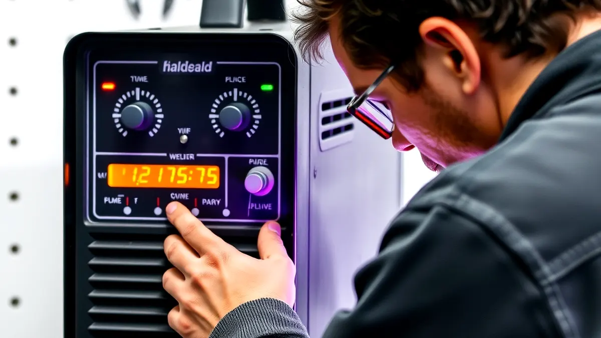
Now the two dials — voltage and wire feed speed — and the skill of reading what they’re doing. Every machine labels them differently (volts and inches-per-minute, or arbitrary dial numbers), so learn your machine’s language by testing rather than memorizing someone else’s chart. Start with the manufacturer’s suggested settings for your wire size and material thickness — our flux core settings guide and detailed amperage chart provide credible starting ranges, and our full wire speed and voltage chart covers the matrix across thicknesses.
Then run a test bead on scrap of the same thickness as your project — never tune on the actual workpiece — and evaluate with three senses:
Sound. A properly set flux core arc makes a steady, continuous frying sound. Too slow a wire feed (or too little voltage) produces a slow, arrhythmic popping — like popcorn hitting the end of its cycle. Too fast a feed produces aggressive snapping and stabbing as the wire drives into the puddle faster than it melts. A machine-gun stutter often means wire speed vastly exceeding voltage’s ability to melt it. Twenty minutes deliberately running beads at “too cold,” “right,” and “too hot” will calibrate your ears permanently — this ear-training is arguably the most valuable half-hour in your entire learning journey.
Sight. Watch the puddle and the bead behind it. The ideal bead sits slightly convex with evenly spaced ripples, wets smoothly into both toes, and holds constant width. Tall, narrow, and ropey means undercooked (add voltage or wire speed). Flat, wide, and spattery means overcooked (reduce voltage before touching speed). A wandering width means your hand, not your dials — technique, which we’re arriving at next.
Slag. Thin, glassy slag that lifts cleanly signals healthy parameters. Thick, stubborn slag suggests travel too slow or settings too cold. Bubbling, pitted slag points to contamination or shielding disruption. The slag is literally reporting on your settings — learn to read it and you’ll catch problems before grinding.
Adjust one variable at a time — a single increment of voltage, or a modest wire speed change — and re-test. Change three things and you’ve learned nothing about what fixed it. This one-variable discipline is the backbone of our systematic troubleshooting method, and it’s what separates deliberate practice from random knob-turning.
Step Four: Your First Bead — Technique Fundamentals
Settings get the arc started; your hands determine what happens next. Four variables define your technique, and beginners can learn all four in a single supervised session.
Gun angle (work angle). Position the gun so it bisects the joint — 45° into the corner for a T-joint fillet, near-vertical for a butt joint on flat plate. This is the work angle, and it determines how heat splits between the two pieces.
Travel direction: drag. Self-shielded flux core is pulled, not pushed. Angle the gun back 10–15° from vertical and drag the puddle along behind the arc. This keeps the flux-generated shielding blanket trailing over the molten metal where it belongs; pushing directs that atmosphere ahead of the puddle and away from where it’s needed. Our dedicated push or pull guide covers the exceptions (gas-shielded processes reverse this) — but for your first thousand flux core inches, drag without hesitation.
Travel speed. Move at a pace that produces consistent bead width — roughly 10–20 inches per minute for beginners on typical settings (faster than most novices expect, slower than their adrenaline wants to go). The visual cue: watch the leading edge of the puddle, not the arc itself. When the puddle’s edge reaches the joint’s side walls and wets them, you’re moving correctly. If the puddle balloons beyond the joint, you’re too slow; if the bead sits on top without wetting the toes, you’re too fast.
Stickout. Hold the 3/4″–1-1/4″ distance steadily through the pass. Body position is the secret: position yourself (kneel, sit, brace your forearm) so the gun travels through its natural arc while angle and distance stay constant. Repositioning mid-weld is allowed and encouraged — stretching is what causes the geometry drift that ruins otherwise good beads.
Practice sequence: strike the arc slightly ahead of where you want the weld to start, establish the puddle, then begin steady travel. Don’t watch the arc flash (even through your lens, staring at the arc fatigues your eyes and degrades puddle reading) — watch the puddle edges. End of bead: hold position for a half-second and feed a touch of extra wire to fill the crater, then withdraw. Crater-filling every stop prevents the depression cracks that plague beginners — a habit to install from bead number one.
Step Five: Welding Real Joints
Once stringers on flat plate look consistent (they will, within a few sessions), move to joints — the shapes you’ll actually encounter in projects.
The T-joint fillet is the workhorse: two plates meeting at a right angle. Set work angle at 45° (bisecting the corner), drag at 10–15°, and run a bead into the joint. The bead should show equal wetting on both plates — if one side wets and the other doesn’t, your angle favors the wrong side; adjust and retest. For joints where the pieces are heavier than a single pass can fill, multiple stringers stacked from root to cap handle the volume — weave only if the joint is wide enough to demand it.
The butt joint (two plates edge to edge) tests fusion at the root. For thin material, a tight fit-up with a single bead works; for thicker plate, bevel the edges and build with multiple passes. Watch for lack of fusion at the root — the classic symptom is a cap bead that looks fine but never actually bonded the bottom edges. Our joint design overview (why weld joints are grooved) explains when beveling is required and why.
The lap joint (one plate overlapping another) needs the arc focused at the toe of the upper plate while ensuring the lower plate’s edge fuses — bias the gun slightly toward the vertical member and watch both edges wet out.
The outside corner is where beginners overheat: thin edges at the corner melt fast, so reduce settings slightly and control travel confidently. Add the preheat consideration only for thick sections; for typical beginner projects (sheet to light plate), keep it simple.
Tack first, inspect, then complete. The rhythm of professional fabrication — fit, tack, check, weld, clean, inspect — becomes automatic surprisingly fast, and it’s the same rhythm regardless of whether the project is a trailer ramp or an art sculpture. For a curated practice progression, our welding practice at home guide sequences projects from trivial to demanding.
Step Six: Multi-Pass Welds and Positions
Real projects exceed single-pass capacity and refuse to stay in flat position. Both are normal — and both have established procedures.
Multi-pass: clean the slag completely between passes (wire brush or chipping hammer — every time, no exceptions; trapped slag inclusions are among the most common code-rejection reasons), then run the next stringer overlapping the previous bead by about half its width. Build from the root outward: root pass, fill passes, cap pass. Sequence matters more than individual bead quality — our parameters guide discusses pass sequencing strategy.
Out of position: the two you’ll meet first are horizontal and vertical-up. Horizontal fillets need slightly reduced heat (gravity pulls the puddle across the joint) — see our horizontal settings guide. Vertical-up — climbing against gravity with each weave segment resting on the shelf below — is the essential structural position: start with reduced settings from your flat baseline, use controlled triangle or crescent weaves with pauses at the toes, and practice on plate before attempting joints. Our complete vertical-up guide provides the numbers and sequencing. Overhead comes later in your progression — when it does, remember the three rules: lowest heat, tight stickout, committed travel.
Position welding is where beginners feel most frustrated, because quality resets with each new position. Expect it, accept it, and put in the deliberate reps — position skill is genuinely new motor learning, not an extension of flat skill, and each position typically needs a few focused sessions to feel natural.
Step Seven: Clean, Inspect, and Learn From Every Weld
The weld isn’t finished when you release the trigger — the last two minutes of each pass determine how much you learn. Chip and brush the slag completely. Then look at what you made with honest, specific eyes (or better, show it to someone more experienced — their thirty seconds of feedback worth hours of solo practice):
- Is the bead width uniform from start to finish? Variation = technique drift (speed, angle, or stickout changing mid-pass).
- Are the toes wetted in (smooth transitions to base metal), or is the bead sitting on top with rounded, rolled edges? Rolled toes = lack of fusion — add heat or slow down.
- Any pinholes? Porosity = contamination, shielding disruption, or damp wire — revisit prep and environment. Our porosity guide maps causes to fixes.
- Any undercut grooves along the edges? Undercut = too much heat focused at the edge, or wrong angle.
- Is the crater filled at the stop? Depression at the end = forgot the half-second fill.
Write one sentence in a notebook: what you ran (settings), what you saw, what you’ll change. That sentence, repeated over weeks, is a learning curve you can literally read. Weld strength, by the way — how much load your finished welds actually carry — is worth understanding properly: our guides to how strong welds are and flux core strength cover what the numbers mean and why technique drives them.
Troubleshooting Your First Welds
Your first projects will produce characteristic problems. Each one has a short list of usual suspects — work through them in order instead of guessing randomly:
Porosity (pinholes everywhere): (1) Clean the metal — oil and rust are the usual culprits; (2) check wind — even flux core’s shielding has limits in strong drafts; (3) verify DCEP polarity; (4) check wire condition — rusted or damp wire off a garage floor spool is a repeat offender (storage guidance in our wire rust prevention guide); (5) confirm stickout is in range.
Excessive spatter: (1) Confirm polarity (the #1 overlooked cause); (2) check stickout length; (3) raise voltage one increment; (4) reduce travel speed if you’re outrunning the puddle; (5) inspect the contact tip — an elongated or worn bore wanders the arc. Full decision tree: our spatter reduction guide.
Wire feeding erratically (chopping, snapping, bird-nesting): (1) Check liner for kinks and debris; (2) verify drive roll tension and correct roll size; (3) check the liner’s length and connections; (4) confirm wire isn’t snagging on the spool or inlet guide; (5) replace a worn contact tip. Feed problems masquerade as arc problems constantly — diagnosing feed first when the arc “acts weird” saves whole evenings. Related: our drive roll setup guide.
Bead won’t stay consistent: technique, almost certainly — slow your pace, reposition for stability, and drill stringers with width-uniformity as your only success metric. If it persists with good technique, suspect the feed system or a loose ground connection.
Cold, lumpy bead with poor fusion: underpowered settings — add voltage and wire speed together, verify stickout (too short = less resistance = less amperage), and check that your machine’s outlet circuit isn’t sagging voltage (a long, thin extension cord on a 110V welder is a classic hidden problem — our guide to wire gauge for welder circuits covers electrical requirements).
The pattern across all five: observe, hypothesize, change one thing, retest. That loop — repeated deliberately — is literally the definition of skill acquisition. For the most complete defect catalogue with visual references, keep our costly flux core mistakes and troubleshooting playbook within reach of your welding cart.
Projects That Build Skill (Instead of Just Testing Patience)
The difference between a project that teaches and one that demoralizes is scope: pick pieces where a flawed weld doesn’t ruin the outcome. The proven beginner progression:
- Flat plate stringers and bead ties — no project, just skill. Judged purely on consistency.
- T-joint fillets on scrap angle iron — the joint you’ll weld most in real life. Stack beads, practice angles.
- A steel workbench or welding table — mostly flat and horizontal joints, immediately useful, forgiving of appearance. Our DIY welding projects collection offers several designs scaled for skill level.
- Repair work — broken brackets, cracked hinges (Priya’s gate), bent implements. Repair teaches joint prep and fit-up because the geometry is dictated to you.
- A frame project (toolbox, cart, grill stand) — introduces squareness, sequencing, and multi-side assembly planning. Tack discipline either saves your project or teaches you why it matters — painfully, once.
- Out-of-position practice — a frame clamped vertically that forces horizontal and vertical-up beads. Uncomfortable by design.
Avoid as first projects: thin-wall tubing (heat control demands come fast), anything load-bearing with consequences (hitches, ramps, structural repairs), and anything precious — welding practice on a family heirloom adds pressure that slows learning. Save the demanding work for when the fundamentals are automatic; our beginner welding tips collection grows with you as the projects get harder.
Maintenance and Consumables: Keeping the Machine Honest
A five-minute maintenance routine keeps your equipment supporting your learning instead of undermining it:
- Wire storage: keep spools indoors and dry; re-seal opened spools in a bag or container. Damp flux core wire causes spatter and porosity that look like technique failures — details in our flux core fundamentals explainer (the core chemistry section makes the storage rules obvious).
- Contact tips: keep spares; replace when the bore wears oval or arcs wander for no other reason. Pennies per tip, hours of frustration saved.
- Liner: inspect annually or when feed becomes inconsistent; a kinked liner pulses your wire feed and, with it, your arc.
- Drive rolls: clean groove buildup; replace worn knurling.
- Ventilation ports: vacuum the machine’s cooling vents — dust-insulated machines hit duty cycle limits sooner (more on thermal management in our duty cycle guide).
- Ground clamp: clean the contact point on the clamp itself; a corroded clamp wastes arc voltage and destabilizes the arc.
Consumable quality deserves the same attention as machine care. Wire, tips, and liners are the three variables between the machine’s electronics and your puddle — cheap wire with inconsistent flux loading undermines everything downstream. Our field review of the best flux core wire brands is the shortcut to choosing well.
The Upgrade Path: When (and Whether) to Add Gas MIG
Here’s the trajectory most welders follow: flux core builds fundamentals outdoors and on imperfect material, then gas-shielded MIG enters the picture for cleaner beads, less fume, better thin-sheet control, and the eventual leap to aluminum. Whether you follow that path depends on your projects, not a rule.
Stay flux core-dominant if your work is structural steel, outdoor repairs, field work, and heavy sections — the process isn’t a stepping stone in those applications, it’s the correct end choice. Add gas MIG when you want cosmetic quality on sheet, reduced post-weld cleanup, lower fume generation for indoor work, or the option to weld aluminum with 100% argon and a spool gun. Our head-to-head of MIG gas vs flux core gives you the crossover criteria, and if the next machine purchase is on your mind, our comparison of buying MIG vs TIG plus the best MIG welders for beginners keeps the decision grounded in how you’ll actually use the machine.
Notice what’s missing from that paragraph: any pressure to upgrade before your flux core fundamentals are solid. Machine-hopping is the most expensive way to avoid practicing — the welder who masters settings, angle, speed, and diagnosis on an entry-level machine will outperform the owner of premium equipment who never learned to read a puddle. Skill transfers; gear doesn’t teach.
The Science Inside the Arc (Plain English Version)
You don’t need an engineering degree to weld well, but a mental model of what’s physically happening in the arc makes every technique rule make sense — and welders who understand the mechanism learn dramatically faster than welders following recipes blindly. Here’s the sequence, stripped to essentials.
When your wire touches the work, a short circuit forms — momentarily — and resistance heats the wire. As it pulls away, the gap ionizes into plasma: the arc, a conductive channel of gas at temperatures reaching roughly 10,000°F at its core — several times hotter than the surface of the sun’s photosphere, and hot enough to melt steel instantly. Heat flows into the workpiece and into the wire simultaneously; the split depends on polarity. On DC electrode positive (our flux core configuration), roughly two-thirds of the heat concentrates at the wire tip — exactly what you want, because the wire must melt fast enough to keep feeding the puddle and activating its flux chemistry. That’s why polarity isn’t a preference — it’s the thermodynamic basis of the whole process.
As the wire melts, three things happen at once: the flux inside decomposes, releasing gases (primarily CO₂-derived atmospheres) that push oxygen away from the molten pool; alloying and deoxidizing elements react with impurities, floating them up into the forming slag; and droplets of molten metal transfer across the arc into the puddle. The slag blanket that forms over the deposited metal shields it from atmospheric oxygen while it cools — the report card we discussed earlier, doing its protective job before it becomes an inspection tool.
The base metal around the weld experiences what metallurgists call the heat-affected zone (HAZ) — an area that didn’t melt but was heated enough for its microstructure and properties to change. On mild steel, a wide HAZ (from excessive heat input or slow travel) can soften the material and reduce toughness; on heat-treated alloys, it can undo the temper entirely. This is the hidden science behind “heat input management” — every technique rule about travel speed, weave width, and voltage ultimately traces back to controlling how much thermal energy the base metal absorbs. The technical resources at TWI (The Welding Institute) and the specification library of the American Welding Society go far deeper if you want the formal treatment — and the general physics of welding arcs are well covered in reference works like Encyclopædia Britannica’s welding overview.
Why does this matter practically? Because it explains the trade-offs you’ll otherwise just memorize: more voltage = longer arc = more heat spread (wider HAZ, more fluid puddle, potential undercut); faster travel = less dwell time = less total energy into the plate (narrower HAZ, faster cooling, potential lack of fusion if overdone); drag angle = shielding follows the puddle (because the atmosphere is generated at the arc and must trail it); stickout = added electrical resistance = more amperage delivered (which is why shortening stickout cools the arc down). When you can derive the rule from the physics, you stop needing to remember it — and you start improvising correctly in situations no chart covers.
Two transfer modes complete the picture. At lower settings, wire feed intermittently contacts the puddle in short-circuit transfer — tiny, frequent short circuits with a characteristic crackling sound; this is the common beginner zone for thin material. At higher settings, droplets detach smoothly in a stream — globular or spray-like transfer — giving deeper penetration and calmer arcs on thicker plate. Flux core’s behavior across this range differs slightly from solid-wire MIG (the flux affects arc dynamics), but the mental model holds: settings select a transfer mode, technique manages the puddle that mode creates, and the sound tells you which mode you’re in.
Electrical Requirements: Powering the Machine Correctly
An often-underestimated pillar of beginner success is the electrical supply feeding your welder. Machines are rated by amperage output, but they pull substantially more from the wall than they deliver to the arc — a 130A 110V welder at full throttle can draw 20+ amps from the circuit, which exceeds a standard 15A household outlet’s continuous capacity. The consequences of ignoring this aren’t subtle: breakers tripping mid-bead, arcs that feel weak despite correct settings, and — worst case — overheated household wiring.
The practical rules: match the machine to the circuit it lives on. A 110V/120V welder wants a dedicated 20A circuit (or the outlet type your manual specifies — many modern units require a 20A receptacle). A 220V/240V machine needs the corresponding outlet and breaker (commonly 30A or 50A depending on capacity). Extension cords are where beginners get burned: if you must use one, it needs to be rated for welder duty at the full length — undersized cords (too small a gauge over too long a run) drop voltage at the machine, and a welder starved of input voltage produces a starved arc. Our electrical guides walk through each piece: what outlet a welder needs, breaker sizing, wire gauge for welder circuits, and generator sizing for portable welding. Electricians and inspectors work from the National Electrical Code maintained by NFPA — when in doubt about a home circuit modification, that’s the standard your electrician will follow, and hiring one for a proper outlet installation costs less than one house fire.
Generator-powered welding (jobsite or backup power) adds its own wrinkle: welders are inductive loads, and inverter machines handle dirty or fluctuating generator power far better than old-transformer designs. Verify the generator’s continuous (not peak) rating exceeds the welder’s draw with margin — our generator capacity guide covers the math, and for shops fed by industrial power, our explainer on converting 3-phase welders addresses the commercial-side equivalent.
Treat your electrical supply as part of the welding system — because it is one. The arc you’re reading, the settings you’re trusting, and the bead you’re judging all begin at the wall outlet, and a weak link there masquerades as every other problem in the troubleshooting list.
Quick-Start Tips That Accelerate the Learning Curve
Collected from the patterns that help beginners most, roughly in the order they become relevant:
- Buy a stack of coupons (scrap plate) before you need them. Dedicate one session purely to settings calibration: beads at cold, ideal, and hot settings, kept side by side as your personal reference library. Memory lies; steel doesn’t.
- Whittle variables. When a weld misbehaves, change exactly one thing — voltage, then speed, then angle — and retest. Random multi-variable changes teach you nothing and often teach you wrong conclusions.
- Listen with your eyes closed, literally. Spend five minutes listening to a good arc without watching it. That sound — steady, even frying — becomes your earliest warning system for parameter drift. It’s the same diagnostic sense professional welders use when troubleshooting blind (our troubleshooting playbook is built around reading these signals).
- Clamp more than feels necessary. Movement mid-weld — from heat, gravity, or a workpiece balanced on a bucket — introduces geometry changes your hands can’t correct fast enough. Clamps are cheap; warped projects are expensive.
- Rest your forearm, lock your wrist. Gun angle drift comes from extremity fatigue more than ignorance. Position so the arm moves as a unit from the shoulder or elbow.
- Weld the whole joint, not the puddle. Beginners fixate on the bright puddle and lose track of direction and endpoint. Keep peripheral awareness of the joint line ahead — direction control improves instantly.
- Grind your restarts. When a bead stops mid-joint, a light grind at the termination before restarting creates a ramp for smooth tie-in — our restart technique is covered in the techniques masterclass.
- Learn from every failure explicitly. After a bad weld, name the defect (porosity? cold lap? undercut?) before diagnosing cause. Vocabulary builds the diagnostic muscle — our mistakes catalogue provides the standard names.
- Watch the toes. The bead’s center mostly takes care of itself; fusion failures live at the edges. Aim your visual attention at where the puddle meets base metal.
- Log your sessions. One line per session — machine, settings, material, one observation. Ten lines later you’ll see patterns no single session reveals; a hundred lines later you have a personal procedure book.
Why This Skill Is Worth the Investment
A brief word on context, because motivation matters during the awkward early weeks when beads look like modern art. Welding remains one of the more accessible skilled trades to enter and one of the more durable to hold: the U.S. Bureau of Labor Statistics counts several hundred thousand welding, cutting, soldering, and brazing jobs nationally, with steady demand projections driven by infrastructure, manufacturing, energy, and transportation work — and median pay that rewards skill development well above entry level (current figures live in the BLS Occupational Outlook Handbook). The barrier to entry is genuinely low — a machine, a stack of scrap, and disciplined practice — while the skill ceiling is genuinely high: certified welding inspectors, pipeline welders, and specialty fabricators occupy some of the best-compensated non-college career paths in the trades.
Even if you never weld professionally, the capability compounds. Metal repairs stop being “find someone who can do it” moments. Projects expand from wood-only to steel. The confidence of being able to join metal — structurally, deliberately, with understanding — changes what you attempt. Our career coverage (is welding a good career?, which welding type is most in demand) explores the professional path for readers who catch the bug, and our beginner welding tips hub serves as your ongoing companion through the progression.
Whether your welding stays a garage skill or becomes a trade, the fundamentals you’re building right now — polarity, settings, angle, speed, diagnosis, prep — are identical across every career and project ahead. Start well, and everything after starts easier.
Glossary: The Terms Your Machine and Manual Use
Every craft has its shorthand, and flux core welding’s vocabulary packs a lot of meaning into short words. Here’s the working glossary — the terms you’ll encounter in machine manuals, setting charts, and any conversation with a more experienced welder.
Arc — the plasma discharge between the wire tip and the workpiece that produces the heat for melting. Not a flame; a conductive column of ionized gas.
Contact tip to work distance (CTWD / stickout) — distance from the contact tip’s end to the work surface. Includes the stickout beyond the tip plus the tip’s position relative to the gun nozzle. Longer stickout = more electrical resistance = more amperage at the arc (within spec limits).
DCEP (DC electrode positive) — the polarity configuration for self-shielded flux core: torch lead to positive, ground to negative. Concentrates heat at the wire, driving melting and flux activation. Sometimes labeled “reverse polarity” on machine faceplates — a naming convention that trips up nearly everyone once.
Duty cycle — the percentage of a ten-minute period a machine can weld at its rated output before thermal overload protection kicks in. A 20% duty cycle means two minutes of welding followed by eight minutes of cooling at that amperage. Lower amperage = longer duty cycle; the curve matters when planning heavier sessions (see our duty cycle guide).
Heat-affected zone (HAZ) — base metal adjacent to the weld that didn’t melt but experienced enough heat to alter its microstructure and properties. Excessive heat input widens the HAZ and can soften steel or over-temper heat-treated alloys.
Penetration — the depth to which the weld metal fuses into the base metal beneath the surface. Distinguished from bead size: a tall bead can sit on top of shallow penetration (a weak weld wearing a confident outfit).
Porosity — gas pockets trapped in solidified weld metal, appearing as pinholes on the surface or cavities inside. Caused by contamination, shielding disruption, damp consumables, or wrong settings. Full diagnosis: our porosity guide.
Slag inclusion — non-metallic slag trapped inside or between weld passes. A genuine internal defect (not just cosmetic) — prevented by complete slag removal between passes.
Stringer bead — a straight, non-weaving bead. The default technique for most flux core work: minimal heat input, maximum consistency, easiest to inspect.
Travel angle — the gun’s tilt relative to vertical along the direction of travel. For self-shielded flux core, 10–15° trailing (drag).
Travel speed — how fast the gun moves along the joint (usually inches per minute). The variable that balances deposition against heat input — too fast gives cold, unfused beads; too slow floods the joint.
Weave — a side-to-side gun motion used to fill wider joints or tie into both toes. Subtypes: crescent, triangle, Z-pattern, and figure-eight. Requires pauses at the toes (where fusion happens) and speed through the middle (where excess heat collects).
Weld procedure / WPS — a written specification defining parameters, materials, technique, and qualifications for a welding job. Formal code work runs on documented procedures derived from standards like those of the American Welding Society; hobbyist work benefits from informal versions (your notebook of known-good settings).
Worm track — squiggly surface channels in a flux core bead caused by gas escaping through the slag at the wrong moment; typically linked to excessive voltage, degraded wire, or stickout issues.
Keep this list reachable while you learn — fluent vocabulary compresses conversations with experienced welders into minutes instead of circular explanations, and it sharpens your own diagnostic thinking: naming a defect precisely is the first step toward fixing it permanently.
Frequently Asked Questions
Do I need a gas cylinder to weld with a flux core MIG welder?
No — that’s the defining advantage of self-shielded flux core wire. The flux inside the tubular wire generates its own shielding atmosphere as it melts, so no external gas is required. You need gas only if (or when) you switch to solid-wire MIG, which uses an external cylinder (75/25 argon/CO₂ for steel, 100% argon for aluminum). Many multi-process machines handle both — the polarity switch is what changes between them.
How do I know my polarity is set correctly?
Self-shielded flux core requires DC electrode positive (DCEP) — torch to positive, ground to negative. Signs of wrong polarity: wild unstable arc, massive spatter, poor penetration, almost no bead build-up. Check your machine’s manual for cable positions or panel switches (many use front-panel cable terminals; some switch electronically), and confirm by reading our polarity guide — it shows exactly what each configuration looks like.
Which wire size should I start with: .030″ or .035″?
For a typical 110V/120V beginner machine, .030″ (0.8 mm) is the versatile starting choice: it runs at lower amperage, feeds more reliably on entry-level hardware, and handles sheet through medium plate. Move to .035″ when your machine has ample power and your projects involve thicker material — more deposition per pass, but it demands more from the feed system. Full comparison: our .030 vs .035 guide.
What settings should I use for my first weld?
Start with the manufacturer’s suggested range for your wire diameter and plate thickness — then tune empirically with test beads. For typical 1/8″ mild steel on a 130–140A 110V machine, that usually means wire feed around 150–220 inches per minute with voltage in the mid-range of the machine’s dial, adjusting until the arc sounds like steady frying and the bead sits slightly convex with even ripples. Our settings guide provides starting points by thickness, and our amperage chart maps the full range.
Should I push or pull with flux core wire?
Pull (drag). Angle the gun 10–15° back from vertical and drag the puddle behind the arc. The flux-generated shielding follows the trailing arc path, covering the molten puddle properly. Pushing with self-shielded wire blows the shielding ahead of the puddle where it can’t protect anything — this mistake causes porosity and poor bead profile. (Gas-shielded processes sometimes reverse this — check our push or pull deep dive.)
Can I weld outdoors with a flux core welder?
Yes — outdoor and drafty-environment capability is flux core’s signature advantage over gas-shielded MIG, which loses its shielding to wind. Flux core tolerates wind far better, though extreme gusts can still disrupt shielding. Other outdoor-friendly traits: it handles light surface rust and mill scale better than MIG, and no cylinder means full portability. Clean the weld zone anyway — outdoors doesn’t mean preparation is optional. Our overview of gasless flux core welding covers outdoor technique specifics.
Are flux core welds strong enough for real projects?
Properly made flux core welds meet the same 70,000 psi minimum tensile requirements as comparable E70 stick and MIG electrodes, and the process is used in structural construction, shipbuilding, and heavy fabrication under code inspection. Strength comes from correct classification, qualified settings, sound technique, and clean base metal — not from the process label. For load-bearing DIY work (trailers, ramps, supports), weld with margin and inspect honestly: see our explainers on weld strength and flux core strength.
What are the most common beginner mistakes?
The big five: (1) wrong polarity — checked before every session until it’s automatic; (2) skipping joint prep — the root cause of most porosity; (3) pushing instead of dragging; (4) inconsistent angle/speed/stickout — solved by deliberate stringer practice and stable body positioning; (5) not filling craters at stops (the classic crack starter). Our catalogue of costly flux core mistakes goes deeper on each, with fixes.
What should I learn after the basics?
Once flat-position joints are consistent: (1) out-of-position welding — vertical-up first, since it’s the most universally useful; (2) multi-pass sequencing for thicker material; (3) parameter diagnosis — learning to identify defects and their causes without help; (4) then process expansion — gas MIG, or stick. Our complete techniques masterclass is the natural next chapter in this guide series, with dedicated positional guides for vertical-up and horizontal work.
Bringing It Together: From Box to Bead
Let’s compress the whole journey into the sequence you’ll eventually run without thinking: clean the joint, clamp and tack, verify DCEP polarity, load quality wire on correct drive rolls, trim to consistent stickout, dial settings until the arc sounds like steady frying, position your body so angle and speed hold constant, drag the puddle with 10–15° of trail, fill every crater, chip the slag, read the bead, write one sentence of notes, repeat. That’s the entire art in twelve verbs — and every single one of them is learnable in an afternoon and refinable for a lifetime.
Priya’s gate, by the way, held. Two years after that first bracket weld — and roughly four hundred practice beads later — she hung a second gate, welded its frame from scratch, and only then allowed herself to admit the thing that first bead had whispered: welding was never a talent she lacked. It was a procedure waiting to be learned, one honest, repeatable step at a time. Your machine is set, your safety gear is on, and the metal is clamped. Start the sequence — and let each weld teach you the one thing the weld before it couldn’t. The skill you’re building isn’t in the machine. It’s in the loop: weld, inspect, adjust, weld again. Everything else in this guide is just the map.