When Was TIG Welding Invented? The True History of GTAW (1941 and Beyond)
When was TIG welding invented? Russell Meredith perfected Heliarc (GTAW) in 1941. Learn the full history, patents, evolution…
READ ARTICLE →Last updated: October 2026
The first aluminum weld I ever made was a disaster — and I mean the textbook kind.
Two pieces of 1/8-inch 6061-T6, clamped flat, machine set to what “looked right” on the dial, tungsten I’d ground to a needle point. I struck the arc, and within four seconds the puddle turned from a shiny silver mirror into a gray, boiling soup that swallowed one plate and left the other untouched. I added filler, got a bead full of black soot, and when I chipped it — well, there was nothing to chip. The whole thing just looked angry.
My instructor looked at the coupon, said four words — “balance is too high” — and turned the cleaning dial down from 85% to 65%. Next coupon: a clean, stacked-dimes bead with proper penetration and a frosty etched zone on either side.
That’s the story of aluminum TIG in miniature: the difference between a ruined part and a aerospace-grade weld is often a handful of numbers on a control panel. Amperage, AC balance, AC frequency, argon flow, tungsten size, filler alloy — get them right and aluminum behaves beautifully; get them wrong and the metal humiliates you.
This guide is built around one practical reference — an aluminum TIG welding settings chart you can actually use at the machine — but it goes deeper than numbers. You’ll understand why the settings are what they are: the physics of aluminum’s oxide layer, the role of alternating current’s cleaning and penetrating halves, how to choose tungsten and filler, how to control heat with a foot pedal, and how to diagnose the defects every aluminum welder meets in their first hundred hours.
We’ll ground it in manufacturer guidance, filler-metal specifications, and safety standards from the organizations that write the rules.
Every quirk of aluminum TIG comes from four material properties. Understand them and the settings chart stops being arbitrary numbers.
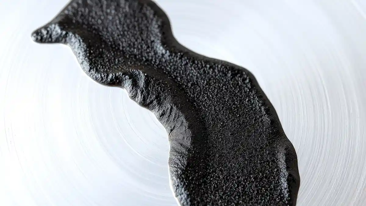
This is the single most important fact in aluminum welding. Pure aluminum melts at about 660°C (1,220°F), but the oxide skin that forms instantly on its surface melts at roughly 2,072°C (3,762°F) — more than three times higher.
If you could somehow weld aluminum with straight polarity (DCEN) the way you weld steel, you’d melt the base metal straight through the oxide layer without breaking it — and the oxide would remain as a floating, contaminated barrier in your puddle, producing a weld with no fusion and full of inclusions.
Alternating current solves this. During the electrode-positive (EP) half-cycle, positively charged argon ions blast the oxide off the surface — you literally see it as a “cleaning zone,” the frosty white etch flanking the bead. During the electrode-negative (EN) half-cycle, the arc drives heat into the metal for penetration. AC alternates between cleaning and penetrating, 120 times per second at 60 Hz. That’s why aluminum TIG requires an AC machine, and why every setting on this chart revolves around managing that alternation.
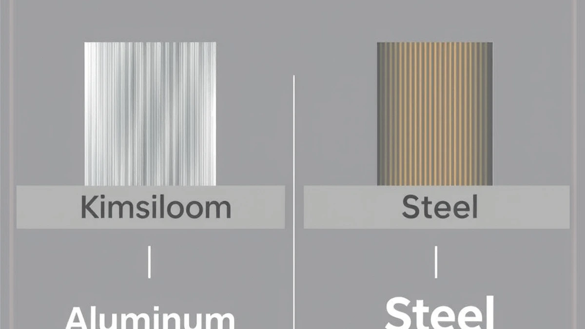
Aluminum conducts heat roughly three to four times faster than carbon steel (around 205 W/m·K versus 50 W/m·K). Heat poured into the joint races away from the arc into the surrounding material.
Consequences:
– You need more amperage than intuition suggests to establish a puddle on thick aluminum — the plate is a heat sink.
– Once established, that same conductivity means heat builds fast — the puddle can go from correct to collapsed in seconds.
– Heat sinking varies with geometry. A plate sitting on a steel table pulls heat away far faster than a plate hanging free. The same thickness needs different settings in different fixtures.
Steel glows — cherry red at around 700°C, bright orange near its melting point. You can see it getting hot. Aluminum stays the same silvery color right up until it suddenly slumps into a shiny liquid pool. The transition from solid to collapsed is nearly instantaneous and visually silent.
This is why experienced aluminum TIG welders trust the shape and reflectivity of the puddle rather than color, and why the foot pedal is not optional equipment — it’s your early-warning system.
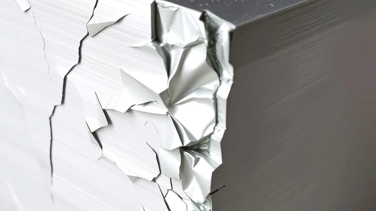
Aluminum expands roughly 1.5 times more than steel per degree of temperature change, so residual stress and warpage are constant companions. Heat input discipline — pulsing, pedal feathering, stitch sequences, proper fixtures — isn’t cosmetic; it’s structural.
Other factors worth knowing:
– Aluminum reflects arc light differently than steel — get your helmet shade right (shade 9–13 for most TIG work).
– Aluminum doesn’t show contamination magnetically — there’s no non-destructive quick check like a magnet test; your preparation discipline is the inspection.
– Alloy matters. 6061-T6, 5052, 3003, 6063, cast alloys — each responds differently to heat and filler. More on that in the filler section.
These properties explain every row of the chart you’re about to use.
Before settings, the machine and accessories:
For context on how TIG compares to other processes — and when it’s worth the setup time — see our MIG vs. TIG comparison and whether TIG is stronger than MIG.
Here is the core reference. These are starting points — your machine, alloy, joint geometry, and ambient conditions will push you up or down within the ranges. Think of the chart as the launch pad and the foot pedal as the flight controls.
| Material Thickness | Amperage (AC) | Tungsten Size | Filler Diameter | Gas Flow (standard cup) |
|---|---|---|---|---|
| 0.020″ – 0.040″ (0.5–1.0 mm) | 15 – 40 A | .040″ or 1/16″ (1.0–1.6 mm) | 1/16″ (1.6 mm) | 10 – 15 CFH |
| 1/16″ (1.6 mm) | 40 – 70 A | 1/16″ (1.6 mm) | 1/16″ – 3/32″ | 15 CFH |
| 3/32″ – 1/8″ (2.4 – 3.2 mm) | 60 – 120 A | 3/32″ (2.4 mm) | 3/32″ (2.4 mm) | 15 – 20 CFH |
| 5/32″ – 3/16″ (4.0 – 4.8 mm) | 110 – 170 A | 3/32″ – 1/8″ (2.4–3.2 mm) | 3/32″ – 1/8″ | 15 – 20 CFH |
| 1/4″ (6.4 mm) | 160 – 230 A | 1/8″ (3.2 mm) | 1/8″ (3.2 mm) | 20 – 25 CFH |
| 3/8″ (9.5 mm) | 220 – 320 A | 5/32″ (4.0 mm) | 3/16″ (4.8 mm) | 25 – 30 CFH |
| 1/2″ (12.7 mm) | 280 – 400 A | 3/16″ (4.8 mm) | 3/16″ – 1/4″ | 30 – 40 CFH |
| Parameter | Starting Setting | What It Does |
|---|---|---|
| AC Balance (EN %) | 65 – 70% EN | Higher % = deeper penetration, less cleaning; lower % = more cleaning, more tungsten heat |
| AC Frequency | 100 Hz (or machine default 60–120 Hz) | Higher Hz = tighter, more focused arc cone; lower Hz = wider, softer arc |
| Pulse (if used) | Peak = chart amperage; background 40–60% of peak; 0.5–5 Hz | Reduces average heat input |
The base chart assumes a butt joint on flat, grounded material. Adjust from there:
| Condition | Adjustment |
|---|---|
| T-joint / fillet weld | +10% to +20% amperage (heat sinks into both plates) |
| Lap joint | Roughly base setting or slightly less |
| Overhead/out-of-position | -10% to counteract fluid puddle |
| Material on heat sink (steel table, heavy fixture) | +10% to +30% — the fixture steals heat |
| Material free-hanging with no backing | -10% to -20% |
| Poor fit-up (gap present) | Fix fit-up; don’t compensate with raw amperage |
| Helium blend (25% He / 75% Ar) | Reduce amperage ~15–25% — helium runs hotter |
| Older/transformer machine vs. modern inverter | Inverters typically run 10–20% lower amps for the same result because of better arc efficiency |
The classic rule of thumb: 1 amp per 0.001 inch of material thickness for a butt joint. So 1/8″ (0.125″) → about 125 amps; 1/16″ (0.062″) → about 62 amps.
Honest assessment of this rule: it’s a decent starting guess for flat butt joints on free-standing plate, but it consistently overestimates for thin material and ignores heat sinking. Modern practice skews slightly lower for thin aluminum (the chart ranges above reflect that) and higher for thick material with cold fixtures. Use the rule to get the dial in the neighborhood, then use the puddle to tell you the truth.
For cross-process comparison of charts and settings discipline, see our TIG welding settings chart for all metals and MIG wire speed and voltage chart.
Beyond the chart, five principles govern the final number:
Cold aluminum needs a burst of heat to break the oxide and get a puddle going. The standard dance:
This is why the foot pedal exists. On aluminum specifically, a set-and-forget machine setting is almost always wrong for the whole length of the weld.
A correct aluminum puddle is a bright, shiny, fluid mirror that wets out evenly at the leading edge. If it sits dull and sluggish, you’re cold — add amps or slow down. If it turns gray, grows faster than your filler, or shows boiling/sugar, you’re hot — ease off or speed up.
Two 1/8″ coupons: one clamped to a massive steel plate, one sitting free on a wooden bench. The clamped one needs noticeably more amperage because the steel is drinking the heat. When you change fixtures, retest your settings.
Adding filler cools the puddle — that’s one of aluminum TIG’s built-in heat controls. A steady dab rhythm lets you run slightly lower amperage than a fusion-only (autogenous) weld would need. Dab into the leading edge of the puddle, not into the arc.
Amperage without travel speed is meaningless — heat input is amperage divided by travel speed, effectively. At chart amperage:
– Too slow → heat builds, puddle collapses, potential burn-through on thin material.
– Too fast → cold lap, no penetration, beads that sit on top.
– Consistent speed with consistent arc length is what turns settings into results.
Related reading on heat-input thinking across processes: flux-core amperage chart and flux-core settings.
The tungsten shapes the arc, and on aluminum the AC arc beats the electrode up. Selection matters.
| Tungsten Type | AWS Color | Best For |
|---|---|---|
| 2% Lanthanated | Blue | The modern all-purpose choice. Excellent AC and DC performance, easy to start, tolerates abuse, works on both inverters and transformers. If you buy one type for aluminum, buy this. |
| 2% Ceriated | Gray | Strong AC performance, slightly softer arc than lanthanated; good for thinner material and battery/low-amp work. |
| Pure (thoriated-free) | Green | The traditional AC-Transformer rod — soft arc, but wears into a ball on AC. Largely obsolete on modern inverters. |
| Zirconiated | Brown | AC transformer machines welding magnesium/aluminum; forms a stable ball. Not ideal on inverter AC. |
| Thoriated (2%) | Red | Excellent on DC (steel/stainless), but not recommended for AC aluminum — radioactive dust when grinding, and poorer AC behavior. |
| WT20/WL20/WP20 | — | AWS classifications: WT20 = thoriated (DC), WL20 = lanthanated (all-purpose), WP = pure. |
Why lanthanated won the market: it starts easily at low amperage, holds a consistent end shape under AC bombardment, and performs across both polarities — which matters when your project mixes aluminum and steel brackets on the same bench. Our guide to what color tungsten for aluminum covers selection in more depth, and what TIG electrode for aluminum reviews specific picks.
Match the chart’s tungsten size to your amperage. Oversized tungsten in low-amperage work gives an unstable, wandering arc; undersized tungsten at high amps means rapid end-melt and contamination. Rule: the smallest tungsten that comfortably carries your amperage.
Aluminum TIG tungsten is ground to a point — but not a needle. The grinding geometry for AC:
Tungsten is only one piece of the electrode story — our difference between tungsten and stainless steel clarifies a common confusion, since both are silvery and sold in rod form.
Argon is the default for AC aluminum TIG because:
– It’s inert — no chemical reaction with molten aluminum.
– It ionizes readily, making AC arc starting and stabilization easy.
– It produces a wide, soft arc with strong cleaning action — ideal for aluminum’s oxide problem.
Helium additions (typically 75% Ar / 25% He or 50/50) create a hotter, deeper-penetrating arc for thick aluminum (generally over 1/4″). Helium’s higher ionization potential raises arc voltage about 30–50% — meaning more energy in the same amperage. The trade-offs: higher cost, more difficult arc starting on AC, and you must reduce your amperage setting to compensate. Most shops use helium blends only for heavy sections where argon alone is too slow.
Helium’s weight is a practical footnote: it’s much lighter than argon and escapes rapidly, so flow rates and draft control matter more with helium blends.
| Setup | Recommended Flow |
|---|---|
| Standard cup (#6–#8) | 15 – 20 CFH |
| Gas lens (#8–#12) | 12 – 18 CFH (laminar flow covers more with less) |
| Thick material / helium blend | 20 – 30 CFH |
| Drafty environment | Increase incrementally; add a draft shield |
| Confined/calm space | Lower end of range |
More gas is not better. Above roughly 30–35 CFH through a standard nozzle, the flow becomes turbulent — it swirls and actually entrains ambient air into the shield, which is the exact opposite of the goal. Symptoms of turbulence: sooty welds, porosity, erratic arc, and a “hissing” sound. If you’re unsure, do the simplest test in welding: hold the lit torch in mid-air and watch the shielding envelope. With a gas lens and proper flow, you should see a long, smooth, invisible column (revealed by a little smoke). If the smoke swirls, your flow is turbulent.
Other gas truths:
– Check for leaks at the regulator and torch fittings — soap solution or an electronic sniffer. A slow leak looks fine until the bottle empties mid-job.
– Venturi-type flowmeters read correctly at the outlet; keep the torch within hose length of accurate reading.
– A loose or missing nozzle, cracked cup, or blocked gas lens ruins shielding even at correct flow — inspect consumables regularly.
– Wind kills shielding. Outdoors, even a light breeze demands a shield or a tented workspace.
Gas choice questions we answer elsewhere: what gas do you use to weld aluminum, can TIG welding be done without gas (spoiler: not for sound welds), and argon pressure for MIG welding for the related GMAW process.
The AC balance control determines how each cycle of alternating current divides its time between electrode-negative (EN) — which drives heat into the base metal — and electrode-positive (EP) — which cleans the oxide.
Machine displays vary:
– “EN%” — a higher number means more time in penetration mode (e.g., 70% EN = 70% of the cycle penetrating).
– Some machines label the scale inverted (“cleaning %”) — read your manual; getting this backwards is a classic beginner error.
| Balance | Cleaning Zone | Penetration | Tungsten Life | Best Used For |
|---|---|---|---|---|
| Low EN (high cleaning, e.g., 55–60%) | Wide, frosty | Shallow | Short (tungsten overheats) | Heavy oxide, cast aluminum, dirty surfaces |
| Standard (65–70% EN) | Moderate, clear etch | Good | Normal | General-purpose work — start here |
| High EN (70–80%) | Narrow | Deep | Longer | Clean material, speed work, thick sections |
Signs you need more cleaning (lower EN%): the oxide isn’t being removed — you see dull, gray, sooty bands on either side of the bead, or the puddle won’t wet into the base metal. Cast aluminum and heavily oxidized material often need aggressive cleaning settings.
Signs you have too much cleaning (high EP): the etch zone is excessively wide and white; the tungsten is rounding off rapidly; the arc sounds harsh; you’re getting tungsten spitting. Dial the EN% up.
A practical observation: modern inverter machines at 65–70% EN handle 90% of aluminum jobs. Castings and heavily contaminated surfaces are the main reasons to deviate.
Balance interacts with everything else — a dirty joint with correct balance still welds badly. Clean first, then tune.
Frequency controls the shape and focus of the arc cone — it doesn’t change cleaning chemistry, but it changes where the energy lands.
| Frequency | Arc Character | Use For |
|---|---|---|
| 60 Hz (transformer standard) | Wide, soft, wandery | Legacy machines; gentle, wide beads |
| 80–120 Hz (modern default) | Moderately focused | General work — most machines default here |
| 150–250 Hz | Tight, pointed, stiff | Precision work, small parts, root access, fillet toes |
Higher frequency = a narrower, more directed arc = better control in tight joints and less heat spread into surrounding material. It also stabilizes the arc noticeably in positions where the arc wants to wander.
The practical effect of pushing frequency up: your puddle narrows and penetrates slightly more precisely; the cleaning zone tightens. The practical effect of pushing it down: a wider, softer, more forgiving puddle — useful on thin material where you want heat spread rather than concentration.
Most modern inverter TIG machines let you adjust frequency in 10–20 Hz increments from roughly 20 to 250 Hz. A good default is your machine’s factory setting (usually around 100 Hz) — adjust only when you have a specific reason.
Pulsing alternates the current between a peak (your chart amperage, which melts and penetrates) and a background (a fraction of peak, which lets the puddle partially solidify), repeating at a set rate.
| Parameter | Starting Point |
|---|---|
| Peak current | Base chart amperage for your thickness |
| Background current | 40–60% of peak (start at 50%) |
| Pulse rate | 0.5 – 2 Hz for general work; 2–10 Hz for thin/speed; up to 50+ Hz (“micro-pulse”) for fine control |
Dialing in: at low Hz (0.5–2 Hz), you see and feel each pulse — good for teaching your hands rhythm. Higher Hz produces smoother, more continuous-looking beads with finer ripples. Match your dab rhythm to the pulse or let the pulse do the timing for you.
Not every machine has pulsing, and plenty of excellent aluminum welding happens without it — but for thin sheet, heat-sensitive alloys, and vertical work, it’s the most useful electronic feature after the foot pedal. Machine-agnostic heat-control technique is covered in our TIG welding tips and tricks.
Filler choice is a settings decision in disguise — the wrong alloy changes how the puddle flows, how the weld cracks, and how the finished assembly performs.
ER4043 (aluminum-silicon, ~5% Si) — the general-purpose filler:
– Fluid puddle, easy to feed, forgiving to beginners.
– The silicon suppresses hot (solidification) cracking in 6xxx-series alloys — its superpower.
– Lower melting range than 5356, slightly less strength.
– Anodizes to a cloudy gray-white — don’t use it if the part will be anodized and appearance matters.
– Ideal for 6061, 6063, cast aluminum, and general fabrication.
ER5356 (aluminum-magnesium, ~5% Mg) — the strength filler:
– Stronger than 4043 (closer to base-metal strength on 5xxx alloys).
– Slightly harder to feed — the puddle is less fluid, the dab rhythm matters more.
– Anodizes closer to the base metal color — preferred for architectural and visible 5xxx work.
– Ideal for 5052, 5086, 5456, marine and structural applications.
– Not ideal for castings and 6061 where cracking resistance is the priority.
| Base Alloy | Recommended Filler | Notes |
|---|---|---|
| 6061 / 6063 (extrusions, general) | ER4043 (or ER5356 when strength/anodizing matters) | 4043’s crack resistance wins for most 6061 work |
| 5052 / 5086 / 5456 (sheet, marine) | ER5356 | Match magnesium content; best mechanical match |
| Cast aluminum (any) | ER4043 (often 4043 with higher silicon) | Castings are crack-prone; 4043’s silicon helps |
| 3003 / 3004 (soft sheet, general) | ER4043 or ER5356 | Both work; 4043 is easier |
| Heat-treated 6061-T6, restraint-heavy joints | ER4043 | Crack resistance prioritized over strength |
| Anodized architectural 5xxx/6xxx | ER5356 | Color match after anodizing |
| Dissimilar (e.g., 6061 to 5052) | ER5356 or ER5154 | Compromise alloys exist; test for the application |
Filler should be roughly the same diameter as the tungsten or the thickness of the joint edge. And clean filler matters: wipe rods with solvent, don’t touch the ends with bare hands, and store them in a closed container — aluminum absorbs surface contamination happily.
This sounds obvious and gets violated constantly in repair shops: running a mild-steel rod (6011, 7018) into aluminum is not welding — it’s making an expensive, brittle mess. Different base metal, different process, different filler. Our cheapest way to weld aluminum guide covers the budget-friendly correct options, including aluminum brazing rods for applications where full fusion welding isn’t required.
If aluminum TIG has a religion, it’s cleanliness. Every porosity-causing contaminant has a name: oxide, oil, cutting fluid, moisture, marker ink, and fingerprints.
A stainless brush used on steel will embed iron particles in aluminum — and your next weld will spit, soot, and crack. Mark your aluminum brush. Keep it with the aluminum. The same applies to grinding wheels, pliers, and clamps.
Castings bring porosity from the casting process itself, oxides, and often paint or release agents. They frequently need:
– More aggressive cleaning settings (lower EN balance for cleaning).
– Grinding out visible surface porosity before welding.
– Patience — trapped gas in castings often bubbles out during welding no matter what you do. Preheating castings to ~200–300°F (95–150°C) reduces the thermal shock and gives trapped gas a chance to escape — but don’t exceed alloy limits, and remember many cast alloys lose strength from overheating. When in doubt, our cast aluminum repair resources discuss alternatives.
For aluminum over about 1/4″ — especially in cold shops — a gentle preheat of 150–250°F (65–120°C) reduces the heat-sink effect, improves starts, and lowers cracking risk. Use an infrared thermometer or heat-indicating crayons; never guess. After welding thick sections, slow cooling (insulating blanket) prevents distortion.
The classic stack-dimes look comes from rhythm: dab-move-dab-move at a consistent cadence — roughly 1 dab per half-inch of travel at normal speeds. Let the puddle wet the rod; the rod should disappear into the puddle, not be poked through it.
Advanced alternatives:
– Weave-and-dip: for wider beads, slight side-to-side motion with dips at each toe.
– Continuous feed: pushing a thin rod steadily into the puddle — common in production work with 1/16″ filler.
Vertical and overhead aluminum TIG are genuinely hard — the puddle is fluid and aluminum conducts heat away fast. Use pulsing or reduced amperage, keep the puddle small, increase dab frequency, and consider a slightly higher AC frequency to tighten the arc. Our vertical welding techniques guide applies across processes.
| Symptom | Likely Cause(s) | Fix |
|---|---|---|
| Black soot/sugar on bead | Contaminated surface; insufficient cleaning action; gas flow problem; wrong balance | Clean with acetone + dedicated brush; lower EN% (more cleaning); check gas lens/cup; reduce turbulence |
| Porosity (pinholes) | Oil, moisture, oxide, or hydrogen in joint; windy workspace; dirty filler | Thorough cleaning; clean filler; shield from drafts; increase gas coverage |
| Crater cracking (at stop) | Arc broken too abruptly; crater left unfilled | Taper pedal down gradually; add final filler dabs to fill crater |
| Cracking along bead | Wrong filler for alloy; high restraint; hot-short alloy (e.g., some 2xxx/7xxx); too much heat | Switch filler (4043 for crack-prone 6061); reduce heat; preheat if procedure allows |
| Weld won’t wet / bead sits on top | Oxide not removed; amperage too low; travel too fast | Brush to bright metal; increase amperage; slow down; verify AC cleaning |
| Gray, dull, frozen puddle | Amperage too low; heat sinking; no foot pedal control | Raise amperage; add pedal; reduce fixture heat sinking |
| Puddle collapses / blow-through | Too much heat; travel too slow; thin material | Back off pedal; speed up; stitch-weld with cooling pauses; lower background/pulse |
| Tungsten spitting / balling excessively | Tungsten contaminated; too much cleaning (low EN%); oversize electrode | Re-grind or replace; raise EN%; downsize tungsten |
| Arc wanders or won’t start | Dull/wrong grind; contaminated tungsten; gas flow turbulent; frequency too low | Regrind longitudinally; check gas; raise frequency |
| Wide frosty zone, etched too far | Too much EP cleaning | Raise EN% (reduce cleaning time) |
| Iridescent/blue discoloration | Insufficient shielding; travel too fast for gas coverage | Check gas leaks and flow; slow down; verify cup integrity |
| Undercut | Too much amperage; travel too fast; pause too long at toes | Reduce amperage; slow down; weave gently with time at center only |
| Warped assembly | Excessive heat input; poor fixturing; wrong sequence | Reduce heat; clamp/fixture properly; stitch-weld; weld alternating sides |
The diagnostic method remains the same as any process: change one variable at a time, test on scrap of identical material and thickness. Our porosity in welding guide walks deeper into the hydrogen/porosity mechanism that troubles every process.
Aluminum TIG is often described as “clean” welding — it is, compared to stick. But the hazards are serious and specific.
A TIG arc produces intense UV across a broad spectrum — enough to cause photokeratitis in seconds and arc burn (“welder’s flash”) on exposed skin. The reflected UV off bright aluminum is also stronger than off dark steel.
The AC arc acting on oxygen generates ozone (O₃) — irritating to airways at elevated concentrations. TIG produces far less metal fume than stick or MIG, but it isn’t fume-free: trace amounts of alloying elements (magnesium, silicon, zinc coatings) can enter the fume, and cutting/grinding in the same area dominates air quality far more than the TIG arc itself. Ventilation is still required — OSHA’s 1910.252 ventilation obligations apply to all welding, cutting, and brazing operations. For context on fume health research, see our are welding fumes toxic summary and is welding bad for your health analysis.
This one deserves its own paragraph because it kills people. Argon is colorless, odorless, and about 1.4× heavier than air — it pools in low areas: pits, tanks, trenches, sumps, and the floor of a poorly ventilated shop. A leaking cylinder or a purged enclosure can displace oxygen below survivable levels with no warning whatsoever.
TIG’s open-circuit voltage (60–80V on many machines) is higher than stick’s — dry footing and intact insulation matter. Hot workpieces conduct heat invisibly — aluminum at 150°C looks identical to aluminum at room temperature; use gloves and tongs, not bare fingers.
The full checklist lives in our welding safety tips resource.
Your settings are only as accurate as your machine’s condition.
| Component | Check | Symptom of Neglect |
|---|---|---|
| Gas lens / nozzle | Weekly: remove spatter, inspect screens | Porosity, turbulent flow, cloudy arc |
| Collet & collet body | For burrs/wear; tight fit on tungsten | Arc wander, gas leaks, loose electrode |
| Torch head/cable | Cracks, water leaks (water-cooled) | Overheating torch, water in gas line |
| Gas hose & fittings | Soap-bubble leak test | Porosity, wasting gas |
| Regulator/flowmeter | Clean seat, accurate reading | Wrong flow, drifting CFH |
| Power source fan/filters | Dust buildup, airflow | Thermal shutdowns, unstable output |
| Ground clamp & cable | Clean contact, no charring | Arc instability, stray current paths |
| Foot pedal | Smooth travel, no dead spots | Jerky heat control |
Common wear parts to keep on hand: tungsten (always), collets, gas lenses, nozzles, and O-rings. A cracked nozzle that “still looks fine” will leak shielding gas and cost you a day of porosity debugging.
Water-cooled torches: check coolant level and concentration monthly; electrolysis and bacterial growth both shorten cooling-system life.
Settings charts take you to the starting line. Skill takes you across it. Here’s a structured path:
Week 1–2: Puddle control, no filler.
Butt joints on 1/8″ 6061, fusion-only (autogenous). Learn to establish, hold, and move a consistent puddle using only the pedal. Goal: straight, uniform beads of consistent width with no collapse.
Week 3–4: Filler introduction.
Same joints, adding 1/16″ or 3/32″ filler on a dab rhythm. Goal: even ripples, no worm tracks (filler added ahead of the puddle), no porosity.
Week 5: Fillet and lap joints.
T-joints on 1/8″ — practice the +15% amperage adjustment and torch angle. Goal: equal legs, good tie-in, no lack of fusion on the vertical face.
Week 6: Positions and edge cases.
Vertical-up on 1/8″, outside corners, thin sheet (1/16″) with pulsed settings, and crater-filling drills (start-stop-start repeatedly on one plate, inspecting every crater).
Week 7+: Real projects.
Bracket fabrication, tube frames, sheet enclosures — each introduces fit-up and fixture variables the coupons didn’t.
Practice principles:
– Weld one coupon, inspect it, write down your settings — build a personal settings log. Within twenty coupons you’ll have a chart better tuned to your machine than any published one.
– Photograph good beads; compare against them later.
– Film yourself (phone on a tripod) — most beginners discover their travel speed doubles under observation.
Programmed practice is covered in how to practice welding at home, and general fundamentals in welding tips for beginners.
Setup: 1″ × 0.065″ wall 6061 tubing, 1/8″ corner joints, ER4043 filler, 1/16″ tungsten, 55–70A pulsed (peak 65A, background 35A, 2 Hz), AC 65% EN.
What happened: Fixtured in a square jig. Dab rhythm matched to pulse. Beads fused fully with minimal heat tint; frame stayed square within 0.5 mm after welding. Total heat distortion negligible thanks to pulsing and alternating weld sequence.
Lesson: On thin, restraint-free tube, pulsed AC at conservative amperage is the difference between a square frame and a banana.
Setup: 0.063″ 5052 sheet, lap and outside-corner joints, ER5356 filler (chosen for strength and eventual anodizing), 40–55A, standard cup at 15 CFH.
What happened: First attempts sooted badly — traced to a breeze from a shop fan. Shut the fan, added a cardboard draft shield, soot disappeared. Beads clean with proper etch zone.
Lesson: Gas coverage, not technique, was the limiting variable. Aluminum outdoors or near doors needs shelter.
Setup: Sand-cast bracket, visible surface porosity and oil staining. Preheated to 250°F, cleaned aggressively, EN balance dropped to 58% for extra cleaning, ER4043, 100–140A.
What happened: First pass pulled trapped gas — small bubbles worked out of the casting. A second pass over the same area with slower travel sealed the surface soundly. Post-weld, the repair held a 300-pound static load in testing.
Lesson: Castings fight back. Preheat, extra cleaning, patience — and sometimes two passes.
Setup: 1/4″ 6061 plate, butt joint on a steel table, ER4043, 1/8″ tungsten, 190A, argon at 20 CFH.
What happened: Chart suggested 160–230A; the steel table swallowed heat so the first attempt at 170A sat cold and gray. Raised to 195A, puddle flowed properly, two passes capped the joint.
Lesson: Heat sinking from fixtures is invisible in a chart — test with the actual fixture in place.
Situation: A customer wanted mild-steel brackets welded to an aluminum plate — a galvanic-corrosion and metallurgical nightmare.
Response: No process welds steel to aluminum soundly. Options discussed: mechanical fastening with isolation, aluminum brazing rods for appropriate joints, or separate components. Our guide to preventing galvanic corrosion explains why dissimilar metals need isolation rather than fusion.
What is an aluminum TIG welding settings chart?
A reference table that matches aluminum thickness and joint type to recommended amperage, tungsten size, filler diameter, and shielding gas flow rate. It gives you machine starting values — the foot pedal and puddle observation then fine-tune within the weld.
What amperage should I use for aluminum TIG?
As a rule of thumb, about 1 amp per 0.001″ of thickness for a flat butt joint — but joint type, heat sinking, and position modify it. Chart starting points: 1/16″ → 40–70A; 1/8″ → 60–120A; 3/16″ → 110–170A; 1/4″ → 160–230A. Add 10–20% for fillets; adjust for fixtures.
Why is AC required for aluminum TIG?
Aluminum’s oxide layer melts at ~3,762°F while the base metal melts at ~1,220°F. The electrode-positive half of the AC cycle blasts the oxide off; the electrode-negative half penetrates the metal. DC alone can’t do both.
What AC balance should I use?
Start at 65–70% EN (penetration). Lower the EN% (more cleaning) for castings or heavily oxidized material; raise it for cleaner, deeper work. If your machine displays “cleaning %,” the scale is inverted — check the manual.
What gas flow rate for aluminum TIG?
15–20 CFH through a standard #6–#8 nozzle; 12–18 CFH with a gas lens; up to 25–30 CFH for thick material or helium blends. Above ~35 CFH you risk turbulence that sucks air into the shield.
What tungsten is best for aluminum?
2% lanthanated (blue) is the modern all-purpose choice — easy starts, stable AC arc, durable. Ceriated (gray) is a good alternative. Avoid thoriated (red) for aluminum: it grinds into radioactive dust and performs poorly on AC.
How do I grind tungsten for aluminum TIG?
Grind lengthwise (longitudinal, tip to tail) on a diamond wheel, 2:1 to 3:1 length-to-diameter, with a slight flat on the tip for AC. Spiral grinding makes the arc wander.
4043 or 5356 filler for aluminum?
4043 (silicon) for 6061, castings, and general work — fluid, crack-resistant, easy. 5356 (magnesium) for 5052/5xxx alloys, higher strength, and anodizing color match. Match the filler to the base alloy.
Can you TIG weld aluminum without filler?
Yes — it’s called autogenous welding, useful for butt joints with perfect fit-up. But filler adds strength and, critically, alters solidification chemistry to resist cracking. Most aluminum work benefits from filler.
Why is my aluminum weld black and sooty?
Insufficient cleaning or insufficient shielding. Contaminants (oil, oxide, dirt) burning in the puddle, or gas coverage broken by wind/turbulence/leaks. Clean aggressively, check gas delivery, and shield from drafts.
Why did my aluminum weld crack?
Common causes: wrong filler (crack-prone combination), crater left unfilled, excessive restraint with too much heat, or welding a heat-sensitive alloy at the wrong temperature. Crater cracking specifically means your termination technique needs work.
Why is my puddle dull and gray instead of shiny?
Too cold (raise amperage), oxide not removed (brush harder/clean better), or cleaning action inadequate (lower EN%). A correct aluminum puddle is a bright, reflective mirror.
Can I use a DC-only welder on aluminum?
No. Aluminum requires AC. DC-only machines can weld steel, stainless, and titanium — but not aluminum soundly. See can you weld aluminum with a MIG welder for the process that (with the right AC/DC machine) also handles aluminum.
Is TIG the best process for aluminum?
For precision, thin material, and appearance — yes. For speed and thicker sections, MIG welding aluminum with a spool gun or push-pull feed is faster. Compare processes in MIG vs. TIG.
How do I prevent distortion in aluminum TIG welding?
Fixture securely, use pulsing or reduced amperage, stitch-weld (skip around rather than running continuous beads), alternate sides, and manage heat-sinking. Distortion is managed in the setup as much as at the torch.
An aluminum TIG settings chart is a map — but the terrain is a puddle that turns from solid to liquid without warning, under an arc that’s simultaneously cleaning and melting. The numbers get you close: start with the amperage row that matches your thickness, set EN balance at 65–70%, frequency near 100 Hz, argon at 15–20 CFH, lanthanated tungsten ground lengthwise, and filler matched to the alloy. From there, the foot pedal and your eyes do the rest.
The principles that never change:
Aluminum TIG has a steeper learning curve than steel welding because the material gives no thermal warning, but the ceiling is high: the same skill set that welds a practice coupon produces the welds that hold aircraft wings, bicycle frames, food-processing tanks, and rocket fuel tanks together. NASA’s own welding standards for aluminum structures rest on exactly these fundamentals.
Set the machine from the chart, clean the metal like it matters, and trust your eyes.
The puddle will tell you everything you need to know.